Transcription
brandsyoutrust.brandsyoutrustField Fabrication ManualFor Plastic Lined Piping
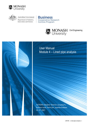
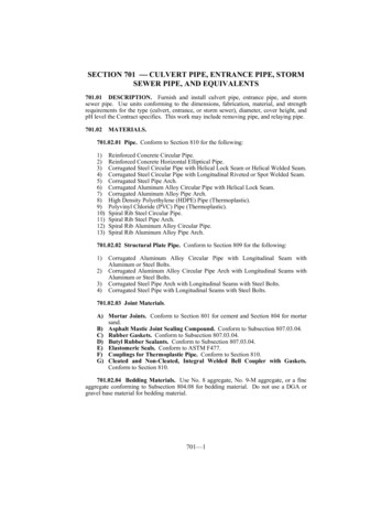
Flanged Plastic-Lined PipeCRANE ChemPharma, Resistoflex plastic-linedpipe is made with a locked-in liner to minimizethe adverse effects of differential thermalexpansion between the liner and the steel.Available liners are: PP, Kynar PVDF,PTFE and PFAThermalok Pipen Stress-relieved linern Carbon steel and stainless steelmaterial optionsn Sizes ranging from 1” - 24” diameterSwaged Pipen Liner in compression for improvedchemical resistancen Sizes ranging from 1” - 8”n Threaded flanges and threadedrotatable flange assemblies onlyn Used for all Conquest and Multi-Axis pipingCONQUEST ConnectionsPlastic-Lined FittingsFittings are available in standard andcustom shapes with multiple lining optionsincluding PTFE, PFA, PP, PVDF, and ETFESpecial Shapesn Custom fittings, manifolds, andsmall vesselsn Lined with TEFZEL ETFEn Available through24” diameter2nnnnPatented flangeless joint designPerformance of a welded systemAvailable in 1” - 4” for all liner typesVirtually zero maintenancennnnHigh-Purity Silicone HosesHigh-Purity Teflon HosesClean-Room assembly packagingVirtually zero maintenanceExpansion Joints of TEFLON n 2, 3, or 5 Convolute constructionn Bolt or cable limitedn Teflon T-62 for maximum flex lifen 1” - 24” Size rangen DI or SS Flanges availableKynar is a registered trademark of Arkema Inc.TEFZEL and Teflon is a registered trademark of E.I. duPont de Nemours and company.www.cranechempharma.com
Table of ContentsIntroductionThe Resistoflex Difference. 4Product Identification. 5Use of this Guide. 6SwagedPipingInitial Procedures. 7Swaged PTFE. 8-9Swaged PFA. 10-11Swaged PP. 12-13Swaged PVDF 1”- 2”.14-15Swaged PVDF 3”- 8”.16-18Thermalok PipingInitial Procedures. 19-20Thermalok PP and PVDF.21-22Thermalok PTFE and PFA. 23-24Thermalok PTFE w/ Swaged Tooling.25-26.ToolingThermalok Tooling.27General Tooling for Thermalok and Swaged.28Swaged Tooling. 29-30PTFE/PP Forming Tool Assembly Details.31PVDF 1”- 2” Forming Tool Assembly Details.32PVDF 3”- 8” Tooling Setup and Rod Adjustment.33PVDF 3”- 8” Forming Tool Assembly Details.34Trouble Shooting Guide.353www.cranechempharma.com
The RESISTOFLEX DifferenceCorrosion resistance of plastic, field convenienceResistoflex Plastic-Lined Pipe combine the best properties of two different materials of construction. On the outside, a metal housing providesstrength, shock resistance, ease of installation, and a high pressure handling capability.On the inside, a plastic lining offers corrosion resistance that even stainless steel and high alloy metals cannot match, at a cost that is generallylower. The thick plastic lining also prevents contamination of high purity fluids.Resistoflex’s field flare designs allow for custom pipes to be manufactured on the job site. Not sure of what pipe spool lengths you will needahead of time? No problem. Both our Thermalok and Swaged piping are available for field flaring. Field flare piping allows you to always havethe correct length of pipe to finish the job.Thermalok Field Flare PipeResistoflex supplies Thermalok Field Flare pipe with moveable liner for our distributors and end users who fabricate finished pipe spools intheir shops. Moveable liner allows the fabricator a wide variety of flange options - rotating welded, or threaded. Thermalok Field Flare tooling isavailable - please see our Tooling and Fabrication section for more information. Available liners are PTFE, PFA, PP, and PVDF.The Thermalok Field Flare product is made with the same process as our standard flanged Thermalok pipe spools, but the relaxing stepis modified to result in a moveable liner. When fabricated by a distributor or end user with Resistoflex tooling and in accordance with ourprocedures, the finished piping has identical performance (pressure/temperature/vacuum) as our standard factory-made pipe spools. All fieldflare piping has been qualified to the rigorous testing requirements of ASTM F1545.Swaged Field Flare PipeSwaged Piping is also available for field flaring and can be customized with twoflange options - rotating or threaded. The process of swaging, as performed on theAbbey Etna Rotary Swager, consists of hammering a metal tube to reduce its diameterto a pipe diameter without grinding or cutting. The same piping used for fieldfabrication is also used for factory spools.4www.cranechempharma.com
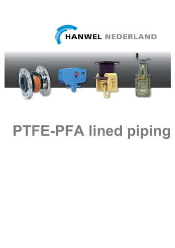
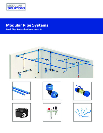
Product Identification GuideSwaged PipeThermalok PipePTFE (Polytetrafluoroethylene)Pure White Color1” - 8” Swaged (CS only)1” - 12” Thermalok (CS and SS)Cable Tie InformationPFA (Perfluoroalkoxy)Semi-Transparent Gray Color1” - 8” Swaged (CS only)1” - 8” Thermalok (CS and SS)Cable Tie InformationPP (Polypropylene)Orange Color*1” - 8” Swaged (CS only)1” - 12” Thermalok (CS and SS)Cable Tie Information* Standard color. Unpigmented availableKynar PVDF (Polyvinylidene Fluoride)Black Color*1” - 8” Swaged (CS only)1” - 8” Thermalok (CS and SS)Cable Tie Information* Standard color. Unpigmented availablewww.cranechempharma.com5
Use of this GuideField Fabrication Manual GuidelinesResistoflex supplies steel pipe lined with four different liner materials: PTFE (Polytetrafluoroethylene), PFA (Perfluoroalkoxy), PVDF (PolyvinylideneFluoride), and PP (Polypropylene). Resistoflex lined pipe can be supplied completely fabricated at the factory to the customer’s specified length,ready for installation. However, if the customer is unable to determine in advance what specific lengths are required for various spool pieces, theymay obtain Resistoflex field flare pipe and fabricate it to length at the job site. Resistoflex offers two types of field flare pipe: Thermalok andSwaged. These field flare pipe spools can be used with the Resistoflex factory-made pipe spools and fittings described in the Resistoflex Designand Layout Manual.This Field Fabrication Manual for Plastic Lined Piping contains instructions for field flaring liners in Resistoflex pipe spools made with threadedor lap joint flanges and containing PTFE, PFA, PVDF, or PP liners. Resistoflex field flare pipe can be fitted with lap joint flanges through the use ofConrac or T-Drill machines or fabricated using pre-flared stub ends.ToolingBefore beginning the fabrication process, confirm that you have all ofthe required tooling. Resistoflex Universal Field Flaring Tool Kits (tableright) streamline the fabrication methods described in this guide byincluding needed tools in one convenient package. For informationon tooling and field flaring techniques for 10” and 12” size pipe, pleasecontact the factory. All tools used in this manual are also availableindividually. For a listing of the tools used in the fabrication process,refer to the tooling section (p. 27-30) of this guide.KitsResistoflex Field Flaring Tool Kit Part 6”8”R29650S-096*R29650S-128*PP0660050 &1”-2” 0754283066005006600433”-4” 074295707858576” - 8” 06604236”-8” 07429650660423*Supplementary KitsWarningIt is important that the procedures and techniques described herein be carefully adhered to, in order to achieve full performance capabilitiesof the finished assembly. Deviation from the prescribed procedures may result in unsatisfactory service life, failure or personnel and/orequipment hazard.These warning signs are found throughout this guide. They are provided to ensure that proper safety measures are taken throughout thefabrication process.For more information on safely using the materials described in this guide, please refer to the Society of the Plastics Industry (SPI) website atwww.plasticsindustry.com.The information contained herein is provided only as a guide for the fabrication of Resistoflex products. Because use, conditions, and applicablelaws may differ from one location to another, and may change with time, the Customer is responsible for determining whether products andthe information in this document are appropriate for the Customer’s use, and for ensuring that the Customer’s workplace and disposal practicesare in compliance with applicable laws and other government enactments. Seller assumes no obligation or liability for the information inthis document. NO WARRANTIES ARE GIVEN; ALL IMPLIED WARRANTIES OF MERCHANTABILITY OR FITNESS FOR A PARTICULAR PURPOSE AREEXPRESSLY DISCLAIMED.Fabrication should be performed only by trained personnel according to the instructions andprocedures outlined herein.6www.cranechempharma.com
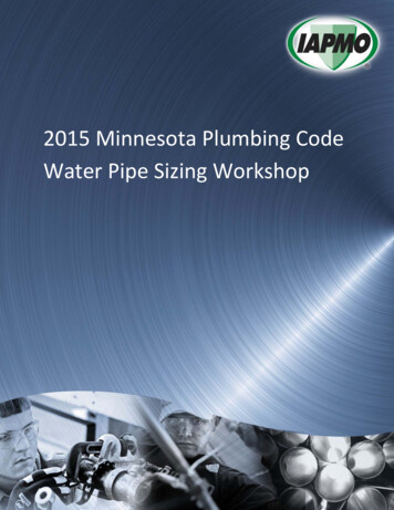
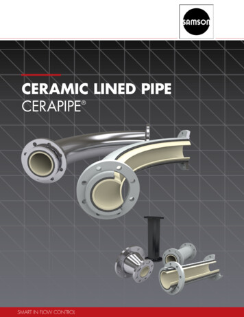
Initial Procedures for all Swaged Piping Fabrication12To determine required finished length “X”,select the proper cut-off length “D” fromthe cutting dimensions table for given linermaterial.NOTE: If spool is being manufactured from apartially finished spool, with one end factoryfinished, use cut-off length “S”.Cut pipe to proper cut-off length “D” usinga sharp angled tip cutter to assure anaccurate cut. DO NOT USE hacksaw orwheel-type cutters. A hacksaw tends to“lead,” which produces non-right-angle cuts.A wheel-type cutter produces a slightlybeveled cut that leaves burrs and can causesevere stress risers in the plastic liner.3Determine the cut-back dimension “E” fromthe cutting dimensions table. Use the sameangled cutter to cut through the metaljust to the surface of the plastic liner at thedistance “E” from the end of the steel shell.Once the tool begins to “break through” thesteel, stop cutting.Cutting Dimension LocationsPTFEPg 9PFAPPPVDF 1”-2”PVDF 4”-8”Pg 11Pg 13Pg 15Pg 18Standard Thread LengthPipe Size(in.)(mm)1”1 1/2”2”3”4”6”8”13/16”1”1 1/16”1 7/16”1 1/2”1 11/16”1 7/8”21262737394348546Remove the cut steel ring from the endof the pipe by inserting the proper sizeguide plug into the pipe and pulling with amodified gear puller.NOTE: A guide plug has two diameters. Choosethe end that fits snugly in the pipe bore.Cut a standard tapered pipe thread onthe end of the pipe with any conventionalthreader to accommodate a chamferedthreaded flange. Use standard threadlength and adjust thread depth to allowflange to be turned on hand tight untilthe last 1½ turns. See chart for standardthread length. Proper fit may be obtainedby adjusting thread depth. To adjust threaddepth, see threader manufacturer’s manual.Rotatable Flange Option: Place flange and stub assembly on pipe with chamfer facing outward.Tighten to turn-up dimension “F” measured from end of plastic face of stub assembly.NOTE: Stub assembly must be beyond hand tight like the chamfered flange.www.cranechempharma.comPlace flange on pipe with chamfer facingoutward. Tighten flange with wrenchuntil turn-up dimension “F” betweenend of plastic stub and face of flangematches requirement shown in the cuttingdimensions table. Also be sure that the boltholes on flanges at either end of pipe spoolare aligned. Flanges must be tightenedwith a flange wrench and must be beyondhand tight. Proper turn up will locate pipeend at bottom of chamfer. Pipe end cannotbe threaded more than 1/2 thread into thechamfer area. If flange turn up is more thethread has been cut too deep.7
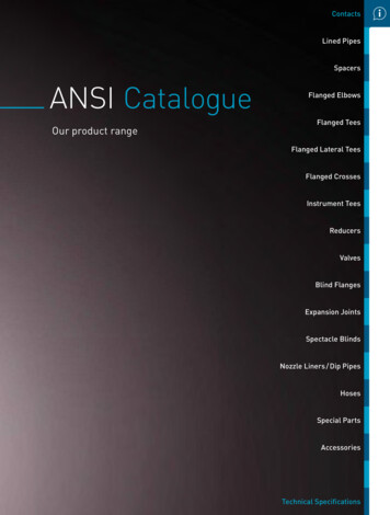
Swaged Polytetrafluoroethylene (PTFE) PipingSwaged Polytetrafluoroethylene (PTFE) PipingJoint Fabrication of 1”-8” Swaged PTFE PipingFor steps 1-6, refer to “Initial Procedures for all Swaged Piping Fabrication” section78Clamp prepared pipe in horizontal orvertical position. Remove any notcheson end of exposed plastic stub usinga file or Vargus de-burring tool. Usinga clean rag and a non-flammabledegreaser that is compatible with theliner, wipe away cutting oil, shavingsand dirt from exposed plastic stub.Vargus De-Burring Tool9Attach flaring die that matches pipediameter. Fit the guide pins in theclamping block assembly to match theflange bolt holes. With the flaring diecentered in the extended liner and thedrive screw retracted, check to makesure the guide pins fit freely in the boltholes with the clamping dogs behindthe flange. If adjustment is needed,loosen the adjusting nuts, center thetool and retighten the nuts.Position the proper patented ventingcollar over the plastic stub and placetight against the flange face, withcurved crimped edge inward, fittinginto flange chamfer. If flange is turnedup too far onto pipe, the venting collarwill stand away from the pipe flange.NOTE: For PTFE, be sure to only use nickel-platedcollar with small perforated holes. DO NOT USEstainless steel collar with large holes, which isdesigned for use with PVDF-lined pipe.NOTE: See Page 31 for forming tool assemblydetails and parts list10“Heat until 25-50% of the plastic stubbecomes translucent.”2-4 minutesWarningWhen field forming, use adequateventilation (indoors, use exhaust fans).Avoid breathing of vapors resultingfrom overheating and possibledegradation of the plastic. Do notconsume food or beverages and do notsmoke during fabrication process. Also,to prevent electrical shock, do not useheat gun near water.8The plastic stub can now be heatedwith a heat gun - attach proper sizeof heat cup to the hot air gun, set theheater dials as shown in chart, andallow the gun to preheat for 15-20minutes. When gun is ready, place gunwith heat cup against the flange andheat until 25-50% of the liner stubsleading edge becomes translucent.Heating time is 2-4 minutes. Frequentlyrotate heat gun to balance heat overplastic surface.Pipe Size1”1 1/2”2”3”4”6”8”Heat -----5-66-777-881010The 110V gun is only recommendedfor heating 1” and 1 1/2” sizes.www.cranechempharma.com
Swaged Polytetrafluoroethylene (PTFE) Piping111213With the flaring die centered in theplastic stub, place the flaring toolguide pins into flange holes and lockclamping dogs in place. Crank theforming die snug to flange. Use cool airor water to speed cooling of plastic toroom temperature. Remove tool onceliner has cooled.Using gloves, gradually insert coneshaped preformed tool into translucentplastic stub until it reaches the flangeface. Allow plastic to cool until endlifts away from preformer beforeproceeding to next step (1” - 4” sizesonly). On 6” - 8”, use preformer to formplastic into trumpet shape. Allow PTFEto turn white before next step.Ensure flare meets minimum flarediameter in chart below.Minimum Flare DiameterPipe SizeNOTE: To assure properly flared face, it isextremely important to cool plastic and flange toroom temperature.14Visually inspect the finished sealingface for a flat, smooth surface and asmooth bend radius.15-To identify plastic liner, be sure toattach the correct color-coded (p. 5)plastic band to the spool.(in)(mm)1”1 7/8481 1/2”2”3”4”6”8”2 11/163 7/164 5/85 15/16810 1/16698811815120425616-A ½” thick plywood cover should bebolted to the flange to protect theplastic face and to prevent the facefrom “remembering” its preformedshape and pulling away from theflange.Spark test the finished face for defectsthat may not be readily visible. Adjustthe sparker to arc about 1” to theflange. Insert probe into the pipe endand circle the inside near the liner. Adefect is identified by apparent majorarcing through the liner. DO NOT USEpipe with a defective liner.17-Attach proper label to plywood cover.For troubleshooting tips,please see page 35.Cutting Dimensions for (PTFE) with Venting Collar1PipeDiameter1”1 1/2”2”3”4”6”8”12D Cut-offE Cut-backF Turn-up2S Cut-off(in)(mm)(in)(mm)(in)(mm)(in)(mm)X 1 3/8X 1 7/8X 2X 2 3/8X 2 1/2X 2 1/4X 2 3/8X 35X 48X 51X 61X 64X 58X 611 1/161 5/161 3/81 9/161 5/81 5/81 3/4273435404242457/81 1/81 3/161 3/81 7/161 7/161 9/1623293135373740X 11/16X 15/16X 1X 1 3/16X 1 1/4X 1 1/8X 1 3/16X 18X 24X 26X 31X 32X 29X 31PTFE venting collars are nickel-plated with small perforated holes.“F” dimension is to the flange face.www.cranechempharma.com9
Swaged PFA Lined Piping (1“ - 4“)Joint Fabrication of 1”-4” Swaged PFA PipingFor steps 1-6, refer to “Initial Procedures for all Swaged Piping Fabrication” sectionFor fabrication of 6” - 8” PFA piping consult factory789Clamp prepared pipe in horizontal orvertical position. Remove any notcheson end of exposed plastic stub usinga file or Vargus de-burring tool. Usinga clean rag and a non-flammabledegreaser that is compatible with theliner, wipe away cutting oil, shavings,and dirt from exposed plastic stub.Vargus De-Burring ToolAttach flaring die that matches pipediameter. Fit the guide pins in theclamping block assembly to match theflange bolt holes. With the flaring diecentered in the extended liner and thedrive screw retracted, check to makesure the guide pins fit freely in the boltholes with the clamping dogs behindthe flange. If adjustment is needed,loosen the adjusting nuts, center thetool and retighten the nuts.Position the proper patented ventingcollar over the PFA stub and placetight against the flange face, withcurved crimped edge inward, fittinginto flange chamfer.NOTE: For PFA be sure to only use nickelplated collar with small perforated holes.DO NOT USE stainless steel collar with largeholes, which is designed for use with PVDFlined pipe.10Pipe SizeHeat SettingsLeisterHeat hen field forming, use adequateventilation (indoors, use exhaust fans).Avoid breathing of vapors resultingfrom overheating and possibledegradation of the plastic. Do notconsume food or beverages and do notsmoke during fabrication process. Also,to prevent electrical shock, do not useheat gun near water.2”71.5-237-81.5-24”82The plastic stub can now be heated with a heat gun; attach proper size ofheat cup to the hot air gun, set the heater dials as shown in chart, and allowthe gun to preheat for 15-20 minutes. For 3 and 4” sizes, preheat the flaringdie to approximately 230 F-110 C during this time, using electric hot plateor additional hot air gun with an oversize heat cup. When gun is ready, placegun with heat cup against the flange and rotate heat gun to balance heatover plastic surface. Heat until liner looks glossy or wet, and no more than1/16” (1.59mm) of liner at end turns clear. DO NOT let liner turn any moretransparent – this is too hot. Squeeze the liner to check softness – it shouldbe firm but flexible.10www.cranechempharma.com
Swaged PFA Lined Piping (1“-4“)1112When the liner is properly heated,spray the preflare tool with moldrelease, then using gloved hand,gradually insert cone-shapedpreformed tool into the PFA stubuntil it reaches the flange face.13With the flaring die centered inplastic stub, place flaring toolguide pins into flange holes and lockclamping dogs in place. Crank theforming die snug to flange – excessforce is not needed. When cooled,remove forming tool and check facefor cracking or splitting. For 4” size,the Enerpac hydraulic tool must beused in the flaring step for bestresults.NOTE: For 4” size, the Enerpac hydraulictool must be used in the preforming stepfor best results.NOTE: To assure properly flared face, it isextremely important to cool plastic andflange to room temperature. Air or watercan be used as the cooling agent.14Visually inspect the finished sealingface for a flat, smooth surface anda smooth bend radius. For spool lengthsless than 3 feet long, leave flaringtool in first end while flaring secondend. This prevents the flare faceof the first end from reheating andlifting from flange. It may take longerto heat the second end because ofthe reduced air flow.Ensure flare meets minimum flarediameter in chart below.Minimum Flare Diameter15-To identify plastic liner, be sure toattach the correct color-coded (p. 5)plastic band to the spool.16-Spark test the finished face for defectsthat may not be readily visible. Adjustthe sparker to arc about 1” to theflange. Insert probe into the pipe endand circle the inside near the liner. Adefect is identified by apparent majorarcing through the liner. DO NOT USEpipe with a defective liner.A ½” thick plywood cover should bebolted to the flange to protect theplastic face and to prevent the facefrom “remembering” its preformedshape and pulling away from theflange.17-Pipe Size(in)(mm)1”1 7/8481 1/2”2”3”4”2 11/163 7/164 5/85 15/166988118151Attach proper label to plywood cover.For troubleshooting tips,please see page 35.Cutting Dimensions for PFA with Venting Collar1PipeDiameter1”1 1/2”2”34”D Cut-offE Cut-backF Turn-up1S Cut-off(in)(mm)(in)(mm)(in)(mm)(in)(mm)X 1 3/8X 1 7/8X 2X 2 3/8X 2 1/2X 35X 48X 51X 60X 641 1/161 5/161 3/81 9/161 5/827333540417/81 1/81 3/161 5/81 7/162229304137X 11/16X 15/16X 1X 1 3/16X 1 1/4X 18X 24X 26X 31X 321PFA venting collar are nickel-plated with small perforated holes.www.cranechempharma.com11
Swaged Polypropylene (PP) PipingJoint Fabrication of 1”-8” Swaged PP PipingFor steps 1-6, refer to “Initial Procedures for all Swaged Piping Fabrication” section7Clamp prepared pipe in horizontal orvertical position. Remove any notcheson end of exposed plastic stub usinga file or Vargus de-burring tool. EnsureOD and ID of liner stub edge is free ofburrs and nicks. Using a clean rag anda non-flammable degreaser that iscompatible with the liner, wipe awaycutting oil, shavings and dirt fromexposed plastic stub.10All hot air guns considered here uselong-life, plug-in type elements, whichwill have extended life if the unit isallowed to cool for 5-10 minutes beforeshutoff. “Cool Air Only” position onLeister 110V and 220V hot air guns isat “0”. Allow gun to preheat for 1520 minutes. The hot air given off bygun during this time should be usedto preheat the molding die to about140 F-60 C, just above “too hot totouch.”89With spring compressed on properforming tool (1” - 4” or 6” - 8” tool)attach molding die that matches pipediameter. Fit the guide pins in theclamping block assembly to match theflange bolt holes. With the molding diecentered in the extended liner and thedrive screw retracted, check to makesure the guide pins fit freely in the boltholes with the clamping dogs behindthe flange. If adjustment is needed,loosen the adjusting nuts, center thetool and retighten the nuts. Removeforming tool and set aside.Pipe SizeHeat �642”6-74-5Attach proper size of heat cup to hotair gun, adjust guide pins to fit flangebolt hole spacing and set heater dialsas shown in table. When forming 1” to2” pipe, use standard heat cup. Whenforming larger pipe, use special baffleheat cup. The heat gun settings areapproximate and may be adjusted tocompensate for ambient temperatureconditions and the length of electricalextension cord used.NOTE: See page 31 for forming tool assemblydetails and parts list.11336-854”866”---78”---7WarningWhen field forming, use adequateventilation (indoors, use exhaust fans).Avoid breathing of vapors resultingfrom overheating and possibledegradation of the plastic. Do notconsume food or beverages and do notsmoke during fabrication process. Also,to prevent electrical shock, do not useheat gun near water.Place heat gun and cup against theflange and rotate cup position every 10seconds to balance heat over surfaceof plastic stub. Heat for 2-4 minutes,until the plastic stub appears to beuniformly wet and glossy, checkingsoftness with clean glove. If pipe isclamped in horizontal position andexcessive plastic droop occurs, rotatepipe to control.12www.cranechempharma.com
Swaged Polypropylene (PP) Piping1213Plastic is ready when the PP liner feelslike rubber and looks shiny. Heatingtime should be at least 2 minutes, tosoften the liner on 1” - 4” size, and 4minutes for 6” - 8” size. Remove hotair gun, then fold end of saggingplastic stub out toward the outsidediameter of the flange and form plasticback to face of flange with a glovedhand. Quickly align molding tool andforming die assembly to the plasticand crank the molding die tight to theflange.1514Allow plastic to cool at least 2 minutesbefore removing forming tool. Whenfinished for the day, allow hot air gunto cool for 5-10 minutes with cool airblowing through the dial position 0,or lowest point on rheostat on Leister110V and 220V hot air guns.Visually inspect the molded face fora flat, smooth surface and a sharptransition between the ID and flareface. PP should not appear radiusedlike other liners.Ensure molded face meets minimumflare diameter in chart below.Minimum Flare DiameterPipe Size(in)(mm)1”1 7/8481 1/2”2”3”4”6”8”2 11/163 7/164 5/85 15/16810 1/16698811815120425616-To identify plastic liner, be sure toattach the correct color-coded (p. 5)plastic band to the spool.17-A ½” thick plywood cover should bebolted to the flange to protect theplastic face and to prevent the facefrom “remembering” its preformedshape and pulling away from theflange.Spark test the finished face for defectsthat may not be readily visible. Adjustthe sparker to arc about 1” to theflange. Insert probe into the pipe endand circle the inside near the liner. Adefect is identified by apparent majorarcing through the liner. DO NOT USEpipe with a defective liner.18-Attach proper label to plywood cover.For troubleshooting tips,please see page 35.Cutting Dimensions for PolypropylenePipeDiameter1”1 1/2”2”34”6”8”1D Cut-offE Cut-backS Cut-offF Turn-up1(in)(mm)(in)(mm)m(in)(mm)(in)(mm)X 1 13/16X 1 3/4X 1 3/4X 2 1/4X 2 1/2X 2 3/8X 3X 47X 45X 45X 58X 64X 61X 771 1/81 1/81 1/81 7/161 5/81 1/21 15/16292929374239501111 5/161 7/161 3/81 11/1626262634373543X 15/16X 7/8X 7/8X 1 1/8X 1 1/4X 1 3/16X 1 1/2X 24X 23X 23X 29X 32X 31X 39“F” dimension is to the flange face.www.cranechempharma.com13
Swaged Polyvinylidene Fluoride (PVDF) PipingJoint Fabrication of 1”-2” Swaged PVDF PipingFor steps 1-6, refer to “Initial Procedures for all Swaged Piping Fabrication” section78Clamp prepared pipe in horizontal orvertical position. Remove any notcheson end of exposed plastic stub using afile or Vargus de-burring tool. EnsureOD and ID of liner stub edge is freeof burrs and nicks. Using a clean ragand a non-flammable degreaser that iscompatible with the liner, wipe awaycutting oil, shavings and dirt from stub.9Set up hydraulic forming tool to propersize and “dry run” into flange bolt holes,checking alignment and centering.Check to make sure the guide pinsfit freely in the bolt holes and theclamping dogs seat firmly behind theflange. If adjustment is needed, loosenthe adjusting nuts, center the tool andretighten the nuts (see graphic nextpage). Remove tool, attach hydraulichose and set aside.Lightly grease the proper size ofaluminum flaring die and preformerwith a high temperature grease.WarningPreheat die to temperature between280 F-138 C (min.) and 300 F-149 C(max.) with hot plate, oven, propanegas stove or torch. Use a pyrometer tomonitor while proceeding to next step.When field forming, use adequateventilation (indoors, use exhaust fans).Avoid breathing of vapors resultingfrom overheating and possibledegradation of the plastic. Do notconsume food or beverages and do notsmoke during fabrication process. Also,to prevent electrical shock, do not useheat gun near water.Vargus De-Burring ToolNOTE: DO NOT HEAT PREFORMER “CONE” DIE. It isused at room temperature.NOTE: See page 32 for forming tool assemblydetails and parts list.1011Attach proper size of heat cup to hotair gun, set heater dials and allow gunto preheat for 15-20 minutes.Pipe SizeHeat -3.01 1/2”5.0-6.02.0-3.02”5.0-6.03.0Position the proper locking collar overthe plastic stub and place tight againstthe flange face, with curved crimpededge inward, fitting into flangechamfer.NOTE: For forming faces of PVDF, be sure to useonly stainless steel locking collars with largeholes. DO NOT USE nickel-plated collar with smallperforated holes, which is designed for use withPTFE and PFA lined pipe.122-4 minutesPlace heat gun and heat cup againstflange, rotate heat cup frequently(10-20 seconds) to heat plastic stubto temperature. Heating time is 2-4minutes. (See page 17 for graphicof proper air flow). When materialis sufficiently heated the liner stubshould be softened to allow it to yieldto a gloved hand, yet still rigid enoughto spring back to shape.14www.cranechempharma.com
Swaged Polyvinylidene Fluoride (PVDF) Piping1314Engage hydraulic forming tool toflange and securely lock flange dogsinto position. Place preformer coneon cylinder pin of tool and advanceforward into plastic stub. Hold in placefor approximately 10 seconds at gaugepressure of 1000 psi (6900 kPa).NOTE: Avoid excessive force on the preformercone to prevent thinning of liner against end ofsteel shell. See graphic below.Preformer Engagement1615WarningHOT flaring dieRelease pressure and retract cylinder.Immediately replace preformer die withpreheated aluminum
Flanged Plastic-Lined Pipe CRANE ChemPharma, Resistoflex plastic-lined pipe is made with a locked-in liner to minimize the adverse effects of differential thermal expansion between the liner and the steel. Available liners are: PP, Kynar PVDF, PTFE and PFA Special Shapes n Custom fittings, manifolds, and small vessels n Lined with TEFZEL ETFE