Transcription
Civil EngineeringUser ManualModule 4 – Lined pipe analysisAUTHORS: Benjamin Shannon, Guoyang Fu,Rukshan Azoor, Ravin Deo, Jayantha Kodikara.05 / 07 / 2021UM M4 – Lined pipe analysis i
QUALITY INFORMATIONDocument: User Manual, Module 4 – Lined pipe analysisEdition date: 05-07-2021Edition number: 1.1Prepared by: Benjamin ShannonReviewed by: Rukshan Azoor, Guoyang FuRevision historyRevisionRevision dateDetailsRevised by1.105-07-21UpdatedBen ShannonUM M4 – Lined pipe analysis ii
CONTENTSContents . iiiAcknowledgements. ivIntroduction . 112Long-term analysis .11.1Step I-Liner properties .21.2Step II – Host pipe properties/soil properties/loading .41.3Step III – Host pipe defects, interface properties and others .51.4Step IV – Outputs .6NPV cost analysis .6Nomenclature . 8Disclaimer . 12References . 12UM M4 – Lined pipe analysis iii
ACKNOWLEDGEMENTSThe Australian Government, through the Cooperative Research Centre, provided funding for the Smart Liningsfor Pipe and Infrastructure Project that produced this report. The CRC Program supports industry-ledcollaborations between industry, researchers and the community.The project was led by the Water Services Association of Australia (WSAA) and included the following projectpartners, all of whom contributed expertise, labour, funding, products or trial sites to assist in the delivery ofthis project.Abergeldie WatertechParchem Construction SuppliesBASF AustraliaSanexen Environmental ServicesBisley & CompanySA Water CorporationCalucem GmbHSouth East Water CorporationCentral Highlands WaterSydney Water CorporationCity West Water CorporationThe Australasian SocietyTechnology (ASTT)Coliban Region Water CorporationDownerGeoTree SolutionsHunter Water CorporationHychem InternationalIcon WaterInsituform PacificInterflowMelbourne Water CorporationMetropolitan RestorationsMonash UniversityforTrenchlessThe Water Research FoundationUK Water Industry Research Ltd (UKWIR)UnitywaterUniversity of SydneyUniversity of Technology SydneyUrban UtilitiesVentiaWater CorporationWilsons Pipe SolutionsYarra Valley WaterNu Flow TechnologiesUM M4 – Lined pipe analysis iv
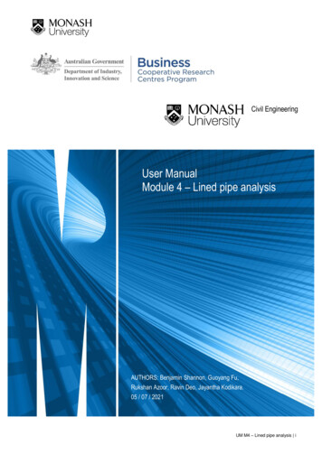
INTRODUCTIONThis document outlines the methods and processes used in the lined pipe analysis (Figure 1), and providesguidelines for its use.Figure 1. Lined pipe analysis module icon in the user interfaceThe primary function of the lined pipe analysis module is to provide an estimate of the liner service life orthickness and a net present value cost analysis. The long-term analysis approach or NPV cost analysis optionsare provided at the start of the module (Figure 2).Figure 2. Long-term analysis and NPV cost analysis1LONG-TERM ANALYSISThe long-term analysis can be conducted for either a single pipe or multiple pipe analysis 1. The calculationprocess is organised into a four-step simple workflow, with basic and advanced properties, to determine either: Liner design thickness or Estimate service life.The thickness or service life calculations are based on the formulas developed at Monash University and fromstandards (ASTM F1216 2016; AWWA 2019).1Multiple pipe analysis will be conducted at a later stage.UM M4 – Lined pipe analysis 1
1.1Step I-Liner propertiesIn the liner properties step, the user is required to select the type of liner, either spray or CIPP, the liner class(A, B, C, or D), and the reinforcement type (FRP or GFRP, for CIPP only). The user interface is given belowin Figure 3:Figure 3. User interface for the failure history step in the pipe level analysis of the liner selection moduleAdvanced parameters are based on generic liner properties, which are explained in the theory manual (TMM4 Part 1 – Determination of liner long-term properties) and were found from literature and Monash Universitytesting (Figure 4).Generic liner parameters were developed from the testing regime conducted at Monash University.Table 1 shows the short-term generic liner properties used in the Platform. Table 2 shows the long-term genericliner properties and Table 3 shows the fatigue properties used in the Platform. For further details on how touse the long-term deterioration coefficients please see TM M4 Part 1 – Determination of liner long-termproperties.UM M4 – Lined pipe analysis 2
Table 1. Generic short-term liner properties for liner type and classTensile strength Tensile modulus(MPa)(GPa)𝜎𝑡ℎLiner th (MPa) modulus ���𝐸𝑓𝑎CIPP C345300.40.0700000.50.0001CIPP B7550324040220.310.0001CIPP A7565656060650.310.0001Spray A-D3535336060330.350.0001Table 2. Generic long-term liner properties for liner type and classStrength reductioncoefficients (hoop)Liner𝑥𝑙Class𝑐𝑙Coefficients for creepmodulus reduction (axial)𝑥𝑙𝒄Coefficients for creepmodulus reduction 652.16-0.2782.16-0.278Table 3. Generic fatigue long-term liner properties for liner typeCoefficients for fatigue strengthreduction (hoop)Liner 1.023GFRP-0.04931.146FRP-0.01330.946Note: Thermal coefficient values have been approximated from literature. Property testing still needs to be conducted.Flexural strength and modulus of Class C CIPP liner were based on a flexible liner (highly ductile resin), hence no flexural strengthwas recorded.23UM M4 – Lined pipe analysis 3
Figure 4. Advanced parameter for liner selection. Values are prefilled based on the basic mode options selected by theuser.1.2Step II – Host pipe properties/soil properties/loadingImplementing the host pipe properties are similar to the other modules (Module 2 and 3, pipe failure analysisand liner selection respectively), where host pipe properties are gathered from pipe cohorts (see TM M2 Part1 – Pipe cohorts). The properties are prefilled based on the pipe material, pipe segment installation year,nominal diameter, operating pressure and soil type. The properties are shown in Figure 5.Figure 5. User inputs host pipe properties/Soil properties/loadingUM M4 – Lined pipe analysis 4
If further information is required to be changed by the user, the Advanced parameters tab can be selected(Figure 6). The host pipe properties including material properties and sizes (gathered from cohort data) canbe modified as well as soil properties (gathered from soil cohort data).Figure 6. Advanced properties for host pipe and soil1.3Step III – Host pipe defects, interface properties and othersStep III involves the host pipe defects such as pipe ovality, initial gap with and gap width due to pulling effectand hole size. Interface properties include the friction coefficient for the liner and host pipe and enhancementfactor. Also included is the percentage of liner service life when out of service. Further details on each of theseparameters can be found in the theory manual (TM M4 Part 2 – Lined pipe analysis). Figure 7 shows the userinterface for Step III.UM M4 – Lined pipe analysis 5
Figure 7. Host pipe defects, interface properties and others1.4Step IV – OutputsIn Step IV, the Platform uses all the data previously filled into the first three steps to calculate either the linerthickness (mm) or the service life (years), depending on the initial selection in Step I. The calculations areperformed using the equations for each of the seven limit states (see TM M4 Part 2 – Lined pipe analysis),depending on the initial Class of liner selected. The results are shown in Figure 8.Figure 8. Outputs from the lined pipe analysis when designing for liner thickness2NPV COST ANALYSISThe net present value (NPV) cost analysis sub module compares three options and computes the NPV costover a period years of analysis. It uses information from the previous modules (pipe length – from pipe libraryand liner lifetime – from long-term analysis) and information to be entered by users.The three options include: Replace Rehabilitate with liner Do nothingUM M4 – Lined pipe analysis 6
Pipe parameters needed for calculations are: length of pipe, 𝐿𝑝 (m), years of analysis (yrs), discount rate, 𝑖(%) and inflation rate, 𝐼𝑁 (%). For each of the options the users need to input the cost per meter (rates shouldbe either found from water utilities or contractors), the pipe or liner lifetime, and the miscellaneous/maintenancecost (annual). The do-nothing option only requires a repair/maintenance cost per failure.The break rate of the pipe can be manually inputted by the estimated number of failures per year/100 km, oralternatively a file can be imported that includes the year and number of breaks per 100 km (this informationcan be gathered from risk modelling or data-driven pipe packages.Figure 9 shows an example of the NPV analysis for the 3 options. A graph of NPV vs. the year after installationis also given. Simple results of the NPV after the years of analysis is also given at the bottom.Figure 9. NPV analysis screen with parameters and graphUM M4 – Lined pipe analysis 7
NOMENCLATURELiner Class (D, C, B, or A)Liner type (CIPP or polymeric spray)Reinforcement type (Glass or polymeric fibres) (for CIPP only)𝐴Area of flow (mm 2)𝑐Patch depth (mm)𝑐𝐴𝐶𝑒External deterioration rate for AC pipes (mm/y)𝑐𝐴𝐶𝑖Internal deterioration rate for AC pipes (mm/y)𝑐𝑑Discharge coefficient𝑐𝑓Fatigue constant for host pipe under cyclic surge pressure𝑐𝑙Coefficient for strength reduction𝑐𝑙𝑐Coefficient for creep modulus reduction𝑐𝑙𝑓Coefficient for fatigue strength reduction𝑐𝑠Intercept parameter for long-term corrosion of metallic pipes (mm)𝐶Compression modulus (GPa)𝐶nothing Cost of do nothing option ( )𝐶𝐻𝑊Hazen Williams roughness coefficient𝐶𝑛Total cash flow for each year ( )𝐶𝑛 (𝑡)Nominal cash flow ( ) at time 𝑡𝐶𝑟 (𝑡)Real cash flow ( ) at time 𝑡𝐶𝑅𝐹Creep retention factor of the liner𝑑Initial hole (defect) size (mm)𝑑𝑓Future hole (defect) size (mm)𝐷Pipe internal diameter (mm)𝐷0Pipe external diameter (mm)𝐷𝐿Liner external diameter (mm)𝐷𝐿𝑖Liner internal diameter (mm)𝐷𝑀Mean diameter of the host pipe (mm)𝐷𝑁Pipe nominal diameter (mm)𝐸𝐴Short-term tensile or compressive modulus of the liner in the axial direction (GPa)𝐸𝐿Short-term modulus of elasticity of the liner (GPa)𝐸𝑎Young’s modulus of the adhesive (GPa)𝐸𝑓ℎShort-term flexural modulus of elasticity (hoop) of the liner (GPa)𝐸𝑓ℎ𝑙Flexural creep modulus (hoop) of the liner (GPa)𝐸𝑓𝑎Short-term flexural modulus of elasticity (axial) of the liner (GPa)𝐸𝑓𝑎𝑙Flexural creep modulus (axial) of the liner (GPa)𝐸𝑙,𝑑𝑟𝑦Dry creep modulus of the liner (GPa)𝐸𝑙,𝑤𝑒𝑡Wet creep modulus of the liner (GPa)UM M4 – Lined pipe analysis 8
𝐸𝑝Modulus of elasticity of host pipe material (GPa)𝐸𝑠Soil modulus (MPa)𝐸𝑡Short-term tensile modulus of elasticity of the liner (GPa)𝐸𝑡ℎShort-term tensile modulus of elasticity (hoop) of the liner (GPa)𝐸𝑡ℎ𝑙Tensile creep modulus (hoop) of the liner (GPa)𝐸𝑡𝑎Short-term tensile modulus of elasticity (axial) of the liner (GPa)𝐸𝑡𝑎𝑙Tensile creep modulus (axial) of the liner (GPa)𝐸𝑡𝑙Tensile creep modulus of the liner (GPa)𝑓Friction coefficient of the interface of the host pipe and liner𝑔Acceleration due to gravity (m/s2)ℎPressure head (m)𝐻Burial depth (mm)𝐻𝑤Groundwater depth (mm)𝑖Discount rate (%)𝐼𝑁Inflation rate (%)𝐼𝑜Initial investment ( )𝑘Lateral earth pressure coefficient𝑘1Patch factor𝑘2Aspect ratio𝐾Enhancement factor𝐾𝐼𝐶Fracture toughness of host pipe material (MPa m1/2)𝐿Installation length of the liner (m)𝐿costCost of the liner ( /m)𝐿misMiscellaneous liner cost ( )𝐿𝑐Critical crack length (mm)𝐿𝑝Length of the pipe (m)𝐿𝑝𝑠Length of the pipe spool (m)𝑛𝑓Cyclic surge factor𝑛𝑃𝐶Number of recurring cyclic surge pressure cycles per day𝑛 𝑇𝑃𝐶Total number of surge pressure cycles for the service life of pipe/lined pipe𝑁Safety factor for host pipe𝑁𝑖Factor of safety for liner imperfections𝑁𝑃𝑉Net present value ( )𝑃Operating pressure (MPa)𝑃𝐺Groundwater load (MPa)𝑃𝐺𝐶Groundwater load capacity (MPa)𝑃𝑁Nominal pressure (bar)𝑃𝑁External pressure on the liner (MPa)𝑃𝑇Test pressure (MPa)UM M4 – Lined pipe analysis 9
𝑃𝑐Recurring cyclic surge pressure (MPa)𝑃𝑚𝑎𝑥Maximum allowable pressure (MPa)𝑃𝑚𝑖𝑛Minimum internal pressure (MPa)𝑃𝑠Surge pressure (MPa)𝑃𝑣Vacuum pressure (MPa)𝑞Host pipe ovality (%)𝑞𝑡Total external pressure on pipes (MPa)𝑞𝑡𝑐Liner capacity for total external pressure (MPa)𝑄Leak rate (L/s)𝑟𝑠Minimum corrosion rate (long-term) of metallic pipes (mm/y)𝑟𝑠ℎLateral corrosion rate for metallic pipes (mm/y)𝑟𝑠𝑣Radial corrosion rate for metallic pipes (mm/y)𝑅costCost of replace option ( /m)𝑅ℎHydraulic radius (m)𝑅misMiscellaneous replace cost ( )𝑅𝑊Water buoyancy factor (unitless)𝑆Slope of the energy grade line, or head loss per unit length of pipe (m/m)𝑡Time (years)𝑡ℎTime (hours)𝑇Pipe wall thickness allowing for uniform corrosion (mm)𝑇𝐿Liner thickness (mm)𝑇𝑒𝑥𝑡Estimated external uniform corrosion (mm)𝑇𝑓AC pipe remaining wall thickness at failure (mm)𝑇𝑖𝑛𝑡Estimated internal uniform corrosion (mm)𝑇𝑛Pipe nominal wall thickness (mm)𝑢𝑔Existing gap width of host pipe (mm)𝑢𝑔𝑝Gap formed due to axial movement or pulling force (mm)𝑉Flow velocity (m/s)𝑊Traffic load (kN)𝑊𝑠Live load (MPa)𝑥𝑙Coefficient for strength reduction𝑥𝑙𝑐Coefficient for creep modulus reduction𝑥𝑙𝑓Coefficient for fatigue strength reduction𝑦𝑓Predicted year for failure of an AC pipe (mm)𝛼Coefficient of thermal expansion/contraction (mm/mm/ C)𝛽Fraction of liner service life when out of service𝛾𝑠Soil unit weight (kN/m 3)𝛾𝑤Unit weight of water (kN/m 3)𝛥𝑇Temperature change ( C)UM M4 – Lined pipe analysis 10
𝜃Rotation angle ( )𝜈𝐿Poisson’s ratio of the liner𝜈𝑝Poisson’s ratio of host pipe material𝜎𝐴Short-term tensile or compressive strength of the liner in the axial direction (GPa)𝜎𝑎𝑑Adhesion strength of the liner to host pipe substrate (MPa)𝜎𝑓ℎShort-term flexural strength (hoop) of the liner (MPa)𝜎𝑓ℎ𝑙Long-term flexural strength (hoop) of the liner (MPa)𝜎𝑓𝑎Short-term flexural strength (axial) of the liner (MPa)𝜎𝑓𝑎𝑙Long-term flexural strength (axial) of the liner (MPa)𝜎𝑚𝑎𝑥Maximum stress in the liner (MPa)𝜎𝑝Tensile stress in the host pipe (for AC pipe) (MPa)𝜎𝑡,𝐴𝐶Ultimate tensile strength of AC (MPa)𝜎𝑡Tensile strength of the liner (MPa)𝜎𝑡Ultimate tensile strength of host pipe material (MPa)𝜎𝑡ℎShort-term tensile strength (hoop) of the liner (MPa)𝜎𝑡ℎ𝑙,𝑟Tensile rupture strength (hoop) of the liner (MPa)𝜎𝑡ℎ𝑙Long-term strength (hoop) of the liner and is the lesser value of either: the tensile rupture strength(hoop), 𝜎𝑡ℎ𝑙,𝑟 (MPa) or fatigue strength (hoop), 𝜎𝑡ℎ𝑙.𝑓 (MPa)𝜎𝑡ℎ𝑙.𝑓Fatigue strength (hoop) of the liner (MPa)𝜎𝑡𝑎Short-term tensile strength (axial) of the liner (MPa)𝜎𝑡𝑎𝑙,𝑟Tensile rupture strength (axial) of the liner (MPa)𝜎𝑦Yield strength of steel (MPa)𝜏Transition period between short-term and long-term corrosion (y)𝛷Soil friction angle ( )𝜙𝑐Wet creep reduction factor𝜙𝑠Wet strength reduction factorUM M4 – Lined pipe analysis 11
DISCLAIMER1. Use of the information and data contained within the Lined Pipe Analysis Module is at your sole risk.2. If you rely on the information in the Lined Pipe Analysis Module, then you are responsible for ensuring byindependent verification of its accuracy, currency, or completeness.3. The information and data in the Lined Pipe Analysis Module is subject to change without notice.4. The Lined Pipe Analysis Module developers may revise this disclaimer at any time by updating the LinedPipe Analysis Module.5. Monash University and the developers accept no liability however arising for any loss resulting from the useof the Lined Pipe Analysis Module and any information and data.REFERENCESASTM F1216 (2016). Standard practice for rehabilitation of existing pipelines and conduits by the inversionand curing of a resin-impregnated tube. In ASTM F1216. ASTM International, West Conshohocken, PA, USA,pp. 1–8.AWWA (2019). Structual classifications of pressure pipe linings. In Suggested proticol for productclassification. AWWA (American Water Works Association), Denver, Colorado, USA.UM M4 – Lined pipe analysis 12
UM M4 - Lined pipe analysis 1 INTRODUCTION This document outlines the methods and processes used in the lined pipe analysis (Figure 1), and provides guidelines for its use. Figure 1. Lined pipe analysis module icon in the user interface The primary function of the lined pipe analysis module is to provide an estimate of the liner service life or