Transcription
ARM END REUSE WATER ASSESSMENTGROUNDWATER MONITORINGArm End150 Spitfarm Road, Opossum BayJune 2018Geo-Environmental Solutions 29 Kirksway Place Battery Point 7004. Ph 6223 1839 Fax 6223 4539
1 Introduction1.1 BackgroundThis proposal concerns the establishment of groundwater monitoring bores at Arm End RecreationalReserve at 150 Spitfarm Road, Opossum Bay (Figure 1). The groundwater monitoring wells are to beestablished for a sufficient period to conclude that ongoing site activities will not cause detrimentalimpact to the environment.1.2 Development ProposalThe recreational reserve will comprise of an 18-hole public (links) golf course (Appendix 1). Otherfacilities include a future clubhouse precinct, public café & shop, a public recreational area with toiletamenities as well as a site maintenance facility including nursery. The fairways are to be irrigatedwith reuse water sourcing from Blackmans Bay wastewater treatment plant (Appendix 2). Wastewatertreatment systems are to be set up on site to manage effluent sourcing from public toilets and theclubhouse. The location of the clubhouse is yet to be formalised.Given annual evaporation rates are greater than annual rainfall rates (GES 2012), it needs to beestablished that nutrients and salts are not concentrating in the system. Given the new irrigationregime, this is less likely to occur (but cannot be ruled out until investigated), and other aspectsrelating to elevated water table may be more important including: Groundwater salinization from leaching of salts in soil above the water table (dryland salinityissues); andPossible residual nutrient flushing.General groundwater quality needs to be assessed in a baseline analysis which can be used as abenchmark for assessing changes in the system which may result from site activities.Herein, GES propose a groundwater monitoring network for the site which is based in a site desktopstudy and include all available information presented within the site development plan. Geo-Environmental Solutions Pty Ltd1
Figure 1 Location of the proposed composting operation2 Geology & GeomorphologyThe promontory of Gellibrand Point is one mass of dolerite covered by various sand and sandstonedeposits and tied to the siltstones of the Opossum Bay - South Arm portion of the peninsula by a largesand bar (spit).Although the Permian sedimentary rocks are not exposed on the site, they are likely to underlie thelower lying sections of the spit (Figure 2). The older Permian rocks which are exposed to the south ofthe site comprise of glaciomarine siltstones and silty sandstones with rare pebbly and fossiliferousbeds (Pua). The overlying sequences are very similar although there is less evidence of the pebblybeds (Pux). Jurassic Dolerite (Jd) has intruded into the Permian strata to the north and is exposedacross much of the higher relief parts of the Peninsula.Quaternary strata uncomfortably overlie these rocks and comprise of: Relatively elevated outcrops of Quaternary sandstone (Maryann Bay Sandstone) - semiconsolidated fine grained marine sand with shell fragments (Qpsb);Paralic clay, silt, sand and minor gravel (Qhi) most likely overlying bedrock across most of thesite;aeolian dune and sheet sand (Qhwd) most likely overlying the clay silt sand and gravel;and windblown and locally derived sand of variable thickness (Qhw).Beach gravel and shingle deposits occur on the tip of the south arm. The likely stratigraphic orderfrom oldest to youngest is presented in the legend of Figure 2. Geo-Environmental Solutions Pty Ltd2
Figure 2 Site Geology & LIDAR Digital Elevation Model (3 x Vertical Exaggeration) Geo-Environmental Solutions Pty Ltd3
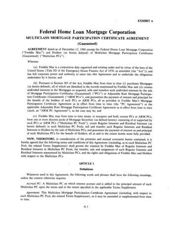
Figure 3 Site Geology, LIDAR Digital Elevation Model (3 x Vertical Exaggeration) & Inferred Groundwater Flow Directions Geo-Environmental Solutions Pty Ltd4
3 Irrigation Water Migration PathwaysThis primary focus of this investigation is to assess areas of the site which may be vulnerable toaccumulation and increased concentrations of nutrients, changes in biological oxygen demand, pH,salinity etc. which may be discharging into the marine environment. Areas where dolerite bedrockis exposed at the site is a lower risk given propensity for rapid water runoff as surface waters or veryshort residence times within the aquifer. The main flow mechanism is expected to be surface waterflow, and where surface water can infiltrate into underlying regolith gravels, groundwater dischargeis expected to be rapid to the shoreline. Surface water monitoring points should be established oncethe site begins to be irrigated.‘Low flow’ zones have been defined in the site Quaternary aquifers which will need to be monitored.These areas are best monitored around the periphery which groundwater will discharge into thereceiving environment.4 Groundwater Monitoring4.1 Groundwater Monitoring Well NetworkGroundwater monitoring wells will be installed at the site to monitor potential issues associated withsite reuse water irrigation. A total of seven groundwater monitoring well locations have beenidentified at the site based on preliminary mapping, interpretation of the site hydrogeology and effectof site activities on aquifer and marine ecosystem vulnerability.These locations (presented in Figure 4) may be varied based on any revised changes to thedevelopment plan. Wells should be established before site works to determine baseline conditions.All the wells are located around the periphery of the site and should not interfere with sitedevelopment works. Groundwater depths are expected to be in the order of 2 to 10 m depth belowground surface. All wells will be screened two (2) metres below the water table to ensure bores willnot dry up due to seasonal trends. There is not considered any value in drilling deeper than 2 m pastthe water table unless clay soils are encountered, and wells are to be established within an underlyingpartially confined aquifer.4.2 Groundwater Well InstallationAll groundwater wells will need to be installed by a suitably qualified person in accordance with theMinimum Construction Requirements for Water Bores in Australia. The following information is to bedocumented when the monitoring wells are installed: A description of the materials used for construction;Initial field measurements of the groundwater for conductivity, total dissolved solids, pH andtemperature;Details of slotted screens installed;Depth of gravel/sand pack;Depth of bentonite cap;Details of bore development during pumping;Results of pump tests;Aquifer levels;A detailed geological log; andThe wells will need to be protected from disturbance and vandalism. Geo-Environmental Solutions Pty Ltd5
Figure 4 Proposed Groundwater Monitoring Well Locations4.3 Monitoring Well DevelopmentThe newly installed wells are to be fully developed 1 well prior to purging for groundwater sampling.The newly installed wells are to be purged of silt particulates for a period until the sand packingbecame effective and the groundwater from the bore became clear. Geo-Environmental Solutions Pty Ltd6
4.4 Monitoring Well Gauging and SamplingTable 1 summarises the procedures for monitoring well gauging and sampling.Table 1 Summary of Monitoring Well Gauging and Sampling ationProcedureSamplepreservationSample holdingtimesProcedure DetailsNewly installed wells were surveyed to an accuracy of 2 mm AHD vertical and 50 mmhorizontal.All groundwater wells were gauged for standing water levels (SWL) from top of casing(TOC) and the presence of Phase Separated Hydrocarbons (PSH) using a Solinstwater/oil/air Interface Probe (IP).Groundwater was extracted from the well using one of the following: Geoprobe peristaltic pump in cases where the well is shallower than 7 m; or a Waterra valve in cases where the well is deeper than 7 m.To ensure a representative groundwater sample could be collected, groundwater was purgedthree (3) times the volume of the well (6 x water column) or purged dry using the chosengroundwater extraction method for well development.The following physiochemical parameters (PCP’s) were monitored whilst purging to ensurethat the aquifer and groundwater parameters had stabilised to within 10% variation of theprevious reading: Reduction / Oxidation potential (REDOX); Temperature; pH; and Electrical conductivity (EC).Dedicated tubing was used at each monitoring well. All reusable equipment (IP) wasdecontaminated using Quantum Clean Laboratory Detergent (R213) and deionized waterbetween each monitoring event.Following groundwater purging, all groundwater samples were collected in laboratorysupplied receptacles, labelled, chilled, and delivered with a COC to National Associationof Testing Authorities (NATA) certified laboratories for analysis within the prescribedholding time.Sample holding times were within acceptable range (based on NEPM B3-2013) fromcollection to extraction.4.5 Groundwater Analysis & Quality ControlGroundwater monitoring bores will be sampled 3 monthly and analysed for both chemical andphysicochemical parameters consistent Environmental Guidelines for the Use of Recycled Water inTasmania (Department of Primary Industries, Water & Environment 2002).Groundwater samples will be taken and processed in accordance with the following: Australian Standards, NATA approved methods, the American Public Health AssociationStandard Methods for the Analysis of Water and Waste Water;Measurement equipment is to be maintained and operated in accordance with themanufacturer’s specifications; andSamples must be tested in a laboratory accredited by the National Association of TestingAuthorities (NATA), or a laboratory approved in writing by the Director, for the specified test.Primary and QC samples were submitted to Analytical Laboratory Services (ALS) for analysis. Table 2presents a summary of the sample analysis including the QC sampling based on AS5667.1 andAS5667.11. Geo-Environmental Solutions Pty Ltd7
Table 2 Overview of Groundwater Analysis and Quality ControlUnitAnalytesTotal Dissolved SolidsCarbonate CO32Bicarbonate HCO3ChlorideIronSulphateFluorideAluminiumDissolved Major Cations (Ca, Na, Mg, K)Sodium Absorption Ratio (SAR)Ammonia as NNitrate Nitrite as NTotal Kjeldahl Nitrogen (TKN) as NTotal Nitrogen as NTotal Phosphorus as PReactive Phosphorus (DRP) as PThermotolerant 111111111111111111111111171117111a – One (1) in ten (10) intra laboratory split (duplicate) samplesb - One (1) in ten (10) inter laboratory split (triplicate) samplec - Single rinse sample per piece of equipment per dayd - Single field blank per day.5 ReportingA quarterly groundwater monitoring report is to be prepared by a suitably qualified geologist/hydrogeologist with experience in groundwater monitoring and contaminant fate interpretation. It isrecommended monitoring should continue for a duration of two years to allow sufficient timeframeto establish any links between site activities and groundwater response.The groundwater monitoring report should include the following: Field based groundwater observations;A summary of site gauging and groundwater physicochemical properties;Groundwater contouring from gauging records with interpretive changes to groundwater flowdirection;Initial calculated groundwater flow rates from discerned hydraulic conductivities andgroundwater gradients;A summary of groundwater analytical results; andField and laboratory quality control assurancesKris TaylorSenior Environmental & Engineering Geologist Geo-Environmental Solutions Pty Ltd8
ReferencesANZECC, 2000.Australian and New Zealand Guidelines for Fresh and Marine Water Quality.Australian and New Zealand Environment and Conservation Council and Agriculture and ResourceManagement Council of Australia and New ZealandANZECC, 2000. Australian and New Zealand Guidelines for the Assessment and Management ofContaminated Sites. Australian and New Zealand Environment and Conservation Council andNational Health and Medical Research Council.AS/NZS 5667.1:1998 Water quality – Sampling, Part 1: Guidance on the design of sampling programs,sampling techniques and the preservation and handling of samples, Standards Australia, 1998.AS/NZS 5667.11:1998 Water quality – Sampling, Part 11: Guidance on the sampling of groundwater,Standards Australia, 1998.Department of Primary Industries Water and Environment. Environmental Guidelines for the Use ofRecycled Water in Tasmania, 2002.GES 2015 Proposed Arm End Golf Course – Preliminary Groundwater Assessment. Geo-EnvironmentalSolutions 2012. Report Written for Experience Consulting.Leaman D.E., 1972. Underground water resources, Arm End-Gellibrand Point, South Arm. MineralResources Tasmania Document TR15 129 132.MCRWBA 2012. Minimum Construction Requirements for Water Bores in Australia. National UniformDrillers Licensing Committee. National Water Commission’s Raising National Water StandardsProgram. Editing, design, and layout by Robee Bureau Services Pty Ltd, West Lakes, South AustraliaPrinted by Doran Printing Pty Ltd, Braeside, Victoria.NEPC, 1999. Guideline on Data Collection, Sample Design and Reporting Schedule B (2), NationalEnvironmental Protection Measure (Assessment of Site Contamination), National EnvironmentProtection Council, 1999.NEPM, 1999.Guideline on Investigation Levels for Soil and Groundwater, Schedule B (1), NationalEnvironment Protection (Assessment of Site Contamination) Measure, National EnvironmentProtection Council, 1999. Geo-Environmental Solutions Pty Ltd9
Appendix 1 Proposed Development Plan Geo-Environmental Solutions Pty Ltd10
Appendix 2 Proposed Reuse Water Pipeline Geo-Environmental Solutions Pty Ltd11
4.1 Groundwater Monitoring Well Network Groundwater monitoring wells will be installed at the site to monitor potential issues associated with . Samples must be tested in a laboratory accredited by the National Association of Testing Authorities (NATA), or a laboratory approved in writing by the Director, for the specified test. .