Transcription
CHAPTER B6HEAT-TRACING OFPIPING SYSTEMSChet Sandberg, P.E.Raychem CorporationMenlo Park, CAJoseph T. LonsdaleSensArraySanta Clara, CAJ. Erickson, P.E.Retired, E.I. DuPont De Nemours & CompanyNewark, DEThe term heat-tracing refers to the continuous or intermittent application of heatto a pipeline or vessel in order to replace heat loss to ambient.1 The major uses ofheat-tracing include freeze protection, thawing, maintenance of fluids at processtemperature (or at pumping viscosities), prevention of fluid component separation,and prevention of gas condensation.The following examples are typical of the diversity of heat-tracing applications:freeze protection of piped water; transfer of molten process chemicals such asphosphoric acid, sulfur, and p-xylene; low-viscosity maintenance of pumped fluidsincluding petroleum products, vegetable oils and syrups, polymeric and resinousmaterials, and aqueous concentrates and slurries; avoidance of condensation andsubsequent improper burning of fuel gas in refineries; preventing moisture fromcondensing out of piped natural gas; preventing freezing of control valves andcompressor damage; elimination of pipeline corrosion due to wet hydrogen sulfideresulting from condensed moisture.2Heat-tracing may be avoided in situations where heat loss to the environmentcan be effectively minimized. In cold climates or areas with severe winters, waterpipes are often buried below the frost line. Alternatively, they may be kept fromfreezing by running them through heated buildings.3In cases where flow is intermittent, tracing might be avoided by designing a selfdraining system such as those used for steam condensate returns. Pipes may alsobe cleared after use by means of compressed air, steam, or solvent flushing or‘‘pigging.’’ The self-draining method is suitable only for infrequently used pipesB.241
B.242GENERIC DESIGN CONSIDERATIONSdue to the high labor costs involved in cleaning and the potential cost and scopeof repair, should a pipe not empty properly.4A third approach in the avoidance of tracing is to design for 100 percent flow.This practice is not recommended since equipment breakdown or process interruption may result in an irreversible drop in the temperature of the piped fluid.TYPES OF HEAT-TRACING SYSTEMSHeat-tracing systems can be divided into two broad classes, electric and fluid. Fluidheat-tracing systems utilize heating media at elevated temperatures to transfer heatto a pipeline. The fluid is usually contained in a tube or a small pipe attached tothe pipe being traced. If steam is the tracing fluid, the condensate is either returnedto the boiler or dumped. If an organic heat-transfer fluid is employed, it is returnedto a heat exchanger for reheating and recirculation. In general, heating of tracingfluids can be provided by waste heat from a process stream, burning of fossil fuels,steam, or electricity.Electric heat-tracing systems convert electric power to heat and transfer it tothe pipe and its contained fluid. The majority of commercial electric heat-tracingsystems in use today are of the resistive type and take the form of cables placedon the pipe. When current flows through the resistive elements, heat is producedin proportion to the square of the current and the resistance of the elements tocurrent flow. Other specialized electric tracing systems make use of impedance,induction, and skin conduction effects to generate and transfer heat.Table B6.1 lists the operating and exposure temperatures and the principalcharacteristics of the different types of heat tracing.FLUID HEAT-TRACINGSteamA number of desirable features made steam the original heat-tracing system ofchoice to maintain process temperature and provide freeze protection. Steam’s highlatent heat from vaporization is ideal for heat-transfer applications. Only a smallquantity is required for a large heating load; and it can heat a line quickly, condenseat constant temperature, and flow to the point of use without pumping. Steam isuniversally available and nontoxic.5Today, energy efficiency and minimization of expensive labor are priority considerations in selecting an economical heat-tracing system. With the advent of highlyreliable electric heat-tracing, the popularity of steam heat-tracing is declining.Steam is more expensive to install and maintain than electric resistance heaters.Periodic leaks and failed steam traps in a steam-traced system waste energy anddemand additional labor costs for repair and replacement. In addition, a singlesteam tracer provides 2 to 10 times more heat than most applications require. Bycontrast, electric tracing systems provide better temperature control and much moreefficient utilization of energy. This means that even though the cost per unit energy islower for steam, total energy costs for electric tracing are usually significantly lower.6In most heat-tracing applications, saturated steam is supplied at pressures of30 to 150 psig (210 to 1035 kPa) (298 F/147 C and 367 F/186 C). The ability to
TABLE B6.1Heat-tracingmethodComparison of Heat-Tracing MethodsMax. operationaltemp.Max. exposuretemp.AdvantagesDisadvantagesHeat transfer fluidsSteam400 F (204 C)NoneTakes advantage of waste steam, explosionenvironment safe, high heat-transfer ratesOrganics500–750 F(260–400 C)250 F (121 C)NoneModerate temperature control, wide temperature range, low freezing temperaturesModerate temperature control; depressesfreezing point, providing protectionagainst freezing when not in use; loweroperating cost than steamGlycols325 F (160 C)B.243Nonuniform heat distribution; expensive toinstall and maintain; imprecise temperature control; wastes energyRelatively expensive; needs a circulating system; leaks can be hazardousRelatively expensive (glycols are cheaperthan heat process fluids); high installedcosts; needs a circulating system; leakscan be hazardousElectricSelf-regulating150–300 F(65–149 C)1190 F (590 C)185–420 F(85–215 C)1500 F (800 C)Zone150–400 F(65–204 C)250–1000 F(121–538 C)Skin effect400 F (204 C)450 F (232 C)ImpedanceUp to failure ofsupply cableand connectionsUp to Curie pointNoneMI cableInductanceNoneWill not burn out—most reliable electricheating cable; energy efficientRugged; capable of high temperature andhigh powerLimited temperature rangeDifficult to field cut; a break in the cablecauses an open circuit; should not becrossed over itself; can be damaged bymoisture penetrationCan be field cut; if a heating element fails,Relatively fragile; can self-destruct from itscircuit is maintainedown heat; can burn out if crossed overitselfSimple components; rugged; needs relatively Impractical for applications less than 5000 ftfew energy inputs; can be part of a prefablong; design is complexricated insulated pipe bundleHigh heat-transfer rates and close temp. con- Expensive custom design; entire pipelinetrol; high temp. capability, heating strucmust be electrically isolated from theture; element cannot burn outsupportHigh-temperature capability; high heat-trans- Very expensive; difficult custom design, notfer ratescommercially exploited
B.244GENERIC DESIGN CONSIDERATIONSFIGURE B6.1 Typical components of a steam-tracingsystem. (I. P. Kohli, ‘‘Steam Tracing of Pipelines,’’ Chem.Eng., March 26, 1979, p. 158, Fig. 1.)continuously remove condensate via a steam trap assembly allows the steam tracerto provide a constant-temperature source of heat.The overwhelming majority of steam-traced piping systems employ externaltracing. Straight runs of the steam pipe or tubes are attached to the pipe, and theentire assembly is covered with preformed sectional insulation (see Fig. B6.1).Valves, fittings, and instruments are heat sinks (system components of large surfacearea and exposed metal surfaces to which system heat will flow and be lost to theenvironment); and to deliver the requisite amount of heat, several loops of thetracing tube are coiled around them before being covered with insulation. Thisconfiguration helps reduce tailing, i.e., the tendency of steam to lose heat andcondense along the line with loss of pressure (see Fig. B6.2).In the majority of applications such as freeze prevention and viscosity maintenance in smaller-diameter pipes, a single tracer provides more than the requiredheat. However, for processes requiring greater heat input, the heat-transfer characteristics of steam tracers can be significantly improved by placing heat-transfercement between the trace and the pipeline, greatly increasing the amount of surfacefor conductive heat transfer.7 Temperatures of steam-tracing systems can vary byas much as 10 F (6 C) between underground pipelines and 20 F (11 C) forpipelines running aboveground. The inability to achieve precise temperature controlis attributed to three factors operating in tandem.81. Saturated steam is delivered at the desired pressure by means of a pressure-
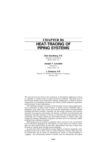
HEAT-TRACING OF PIPING SYSTEMSB.245FIGURE B6.2 ‘‘Coiling’’ arrangement for tracing valves, flanges, casings, and instruments.Coils act as expansion joints for steam tracing systems. (I. P. Kohli, ‘‘Steam Tracing ofPipelines,’’ Chem. Eng., March 26, 1979, p. 159, Fig. 3.)reducing valve. As the pressure is reduced, the saturated steam becomes superheated. The excess heat is rapidly dissipated in the system.2. Uneven contact between the steam tracer and process pipe produces an unevendistribution of temperature. This effect becomes more significant as the temperature difference between pipe and tracer increases. When the steam becomessuperheated, the temperature difference reaches a maximum.3. Tailing also affects the temperature of the surrounding steam.A more precise control of steam tracer temperature can be achieved by the useof steam jacketing (see Fig. B6.3) or temperature-sensitive steam valves. However,these methods are rarely used as they provide a level of temperature control inferiorto that of electric heat-tracing, and at a significantly greater cost.Circulating MediaCirculating media are the most expensive heat-tracing systems and are specifiedfor special-process or ambient conditions (see Table B6.1 and Ref. 9). The virtueof circulating fluids is the ability to provide protection and reasonable control attemperatures above and below those achievable with steam-tracing. Circulatingmedia systems can be separated into two classes; oils and organic heat-transfer
B.246GENERIC DESIGN CONSIDERATIONSFIGURE B6.3 Steam jacketing is expensive and employedonly in special high-heat-demand situations. (I. P. Kohli,‘‘Steam Tracing of Pipelines,’’ Chem. Eng., March 26, 1979, p.159, Fig. 2.)fluids suitable for high-temperature applications, and glycols with antifreeze properties that make them especially useful in cold climates, where they will not freezeeven when used intermittently.ELECTRIC RESISTANCE HEAT-TRACINGIntroductionSignificant commercial use of electric heat-tracing began to take hold in the 1950s.Electric heat-tracing served as a visible alternative in situations where steam couldnot be used or was impractical. Typical early applications included the electrictracing of transfer lines for oil, asphalt, and waxes. Electric tracing proved especiallyuseful for long runs of pipe. [Steam tracers are generally limited to runs of 100 to200 ft (30 to 60 m). Tracing long or multiple pipe runs with steam can significantlyincrease both tracing complexity and cost.]At the outset, hardware had to be adapted from other resistance heating applications. Lead-sheathed soil-heating cable was used extensively for waterline freezeprotection while longer runs of pipe were traced with mineral-insulated coppersheathed cable. For higher-temperature service, tubular heaters (normally usedfor immersion and clamp-on applications) were converted for pipe tracing, andcontrollers were adapted from furnaces and consumer appliances in order to control temperature.Self-Regulating HeatersSince their introduction in 1971, self-regulating heaters have become the mostpopular form of electric heat-tracing and are currently offered by most major
HEAT-TRACING OF PIPING SYSTEMSB.247vendors of industrial heat-tracing. Self-regulating heat-tracing has an advantagewith respect to other heat-tracing products because this technology eliminates thepossibility of heater burnout due to the inability to dissipate internally generatedheat—the most common cause of heater failure (Fig. B6.4).FIGURE B6.4 Components of a self-regulating parallel resistance heat-tracer. (ChetSandberg, Electrical Heat Tracing Systems for Use in Pulp and Paper Plants; Considerations for the 1990’s. ISA Pulp and Paper Industries Division Symposium (in conjunctionwith TAPPE), Nashville, TN, March 1993.)Self-regulating tracers are usually provided in the form of a heater strip consistingof two parallel 20 to 10 American wire gauge (AWG) bus wires embedded in aconductive polymer core, which serves as the heating element and over which apolymeric insulator is extruded. The entire assembly is then covered with a metalbraid to provide grounding and additional mechanical protection. Another polymerjacket can be added (see Fig. B6.4). The heater core consists of carbon particlesembedded in a polymer matrix. Heat is generated by resistance to current flowingthrough the conductive polymer heating element. As the temperature of the conductive core increases, so does the electric resistance. The result is a diminishing outputof heat for each successive increment of temperature elevation. Since power outputis a function of temperature at any location in the element, the conductive corebehaves as a temperature-sensitive rheostat guarding against low- as well as hightemperature failure (see Figs. B6.5 and B6.6).Self-regulating tracers can be cut to any desired length and field-installed withinthe limitations of the voltage drop on the bus wires. They have good impact resistance and are routinely handled in the field. The self-regulating feature pro-FIGURE B6.5 Relationship of resistive properti
B.246 GENERIC DESIGN CONSIDERATIONS FIGURE B6.3 Steam jacketing is expensive and employed only in special high-heat-demand situations. (I. P. Kohli, ‘‘Steam Tracing of Pipelines, ’’ Chem. Eng., March 26, 1979, p. 159, Fig. 2.) fluids suitable for high-temperature applications, and glycols with antifreeze proper-ties that make them especially useful in cold climates, where they will .