Transcription
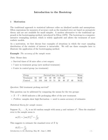
TH8320U and TH8321U Touch ScreenProgrammable ThermostatsINSTALLATION INSTRUCTIONSAPPLICATIONThe TH8320U and TH8321U Touch Screen Universal Programmable Thermostats provide electronic control of 24 Vacheating and cooling systems or 750 mV heating system. See Table 1 for a general description.Table 1. TH832 Thermostats Description.ModelTH8320UPowerMethodBatteries orcommon wireTH8321UChangeoverSystem SelectionFan SelectionAutomatic ormanualselectableHeat-Off-CoolAuto (Em. Heat forheat pumps)On-Auto-CircCommentsSystem and Fan selectionvary based on system typeSystem and Fan selectionvary based on System type.Humidity sensor to controldehumidification.Selecting LocationMERCURY NOTICEIf this control is replacing a control that containsmercury in a sealed tube, do not place your oldcontrol in the trash. Dispose of properly.Install the thermostat about 5 ft. (1.5m) above the floor inan area with good air circulation at average temperature.See Fig. 1.Contact your local waste management authorityfor instructions regarding recycling and theproper disposal of the old control.INSTALLATIONYESNOWhen Installing this Product.1.2.3.4.NORead these instructions carefully. Failure to followthe instructions can damage the product or causea hazardous condition.Check the ratings given in the instructions to makesure the product is suitable for your application.Installer must be a trained, experienced servicetechnician.After completing installation, use these instructionsto check out the product operation.5 FEET[1.5 METERS]NOM19925Fig. 1. Selecting thermostat location. U.S. Registered TrademarkCopyright 2004 Honeywell International Inc. All Rights Reserved69-1706
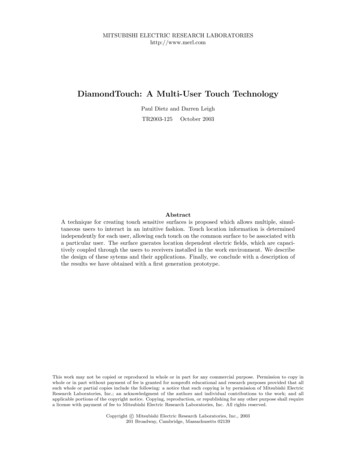
TH8320U AND TH8321U TOUCH SCREEN PROGRAMMABLE THERMOSTATSDo not install the thermostat where it can be affected by:— Drafts or dead spots behind doors and in corners.— Hot or cold air from ducts.— Radiant heat from sun or appliances.— Concealed pipes and chimneys.— Unheated (uncooled) areas such as an outside wallbehind the thermostat.3.4.5.HEAT PUMPCONVENTIONALInstalling WallplateY2CAUTIONElectrical Hazard.Can cause electrical shock or equipmentdamage.Disconnect power before wiring.2.Y2REWO/BAUXW2YYS1S1GGS2S2CCPosition and level the wallplate (for appearanceonly).Use a pencil to mark the mounting holes.System TypeWALL ANCHORS (2)Standard Heat/CoolMOUNTINGHOLES (2)MOUNTINGSCREWS (2)M19916Fig. 2. Mounting wallplate.5.M19951Table 2. Selecting Terminal Identifications forSystem Type.WIRES THROUGH WALLAND WIRE SLOT4.RCRFig. 3. Selecting terminal identifications forsystem type.WALL3.RCLSCREW TERMINALSThe thermostat can be mounted horizontally on the wallor on a 4 in. x 2 in. (101.6 mm x 50.8 mm) wiring box.1.Securely tighten each screw.Push excess wire back into the hole.Plug the hole with nonflammable insulation toprevent drafts from affecting the thermostat.Remove the wallplate from the wall and, if drywall,drill two 3/16-in. holes in the wall, as marked. Forfirmer material such as plaster, drill two 7/32-in.holes. Gently tap anchors (provided) into the drilledholes until flush with the wall.Position the wallplate over the holes, pulling wiresthrough the wiring opening. See Fig. 2.Insert the mounting screws into the holes ionalWiringDiagramReference5, 6Heat OnlyConventional7Heat Only with FanConventional8Heat Only Series 20Conventional9Cool OnlyConventional10Standard Multistageup to 2 Heat/2 CoolConventional11, 12Heat Pump with NoAuxiliary HeatHeat Pump13, 14Heat Pump withAuxiliary HeatHeat Pump15, 16WIRING (FIG. 5-16)All wiring must comply with local electrical codes andordinances.1.2.M19917Select set of terminal identifications (Table 2) thatcorresponds with system type (conventional orheat pump in Fig. 3).Loosen the screws for the appropriate system typeselected; see Table 2. Insert wires in the terminalblock under the loosened screw. See Fig. 4.69-1706Fig. 4. Inserting wires in terminal block.IMPORTANTUse 18 gauge thermostat wire.2
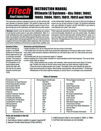
TH8320U AND TH8321U TOUCH SCREEN PROGRAMMABLE Y221RW2S1S2COPTIONAL24 VACCOMMONCONNECTION321RCOPTIONAL24 URESENSORRCRWYGCHEAT ACTOR1POWER SUPPLY. PROVIDE DISCONNECT MEANS AND OVERLOADPROTECTION AS REQUIRED.1POWER SUPPLY. PROVIDE DISCONNECT MEANS AND OVERLOADPROTECTION AS REQUIRED.2FACTORY INSTALLED JUMPER.2FACTORY INSTALLED JUMPER.33OPTIONAL OUTDOOR OR INDOOR REMOTE SENSOR. AVAILABLEON SELECT MODELS. WIRES MUST HAVE A CABLE SEPARATEFROM THE THERMOSTAT CABLE.M19895OPTIONAL OUTDOOR OR INDOOR REMOTE SENSOR. AVAILABLEON SELECT MODELS. WIRES MUST HAVE A CABLE SEPARATEFROM THE THERMOSTAT CABLE.M19897HEAT RELAYFig. 7. Typical hookup of heat-only system(1H conventional).Fig. 5. Typical hookup of conventional single-stageheat and cool system with single transformer(1H/1C YGC21RCOPTIONAL24 VACCOMMONCONNECTIONC3OPTIONAL24 FANRELAYHEAT RELAYFANRELAYCOMPRESSORCONTACTORHEAT RELAY1CR1POWER SUPPLY. PROVIDE DISCONNECT MEANS AND OVERLOADPROTECTION AS REQUIRED.2REMOVE FACTORY INSTALLED JUMPER.3OPTIONAL OUTDOOR OR INDOOR REMOTE SENSOR. AVAILABLEON SELECT MODELS. WIRES MUST HAVE A CABLE SEPARATEFROM THE THERMOSTAT CABLE.M198961POWER SUPPLY. PROVIDE DISCONNECT MEANS AND OVERLOADPROTECTION AS REQUIRED.2FACTORY INSTALLED JUMPER.3OPTIONAL OUTDOOR OR INDOOR REMOTE SENSOR. AVAILABLEON SELECT MODELS. WIRES MUST HAVE A CABLE SEPARATEFROM THE THERMOSTAT CABLE.M19898Fig. 8. Typical hookup of heat only system with fan(1H conventional).Fig. 6. Typical hookup of conventional single-stageheat and cool system with two transformers(1H/1C conventional).369-1706
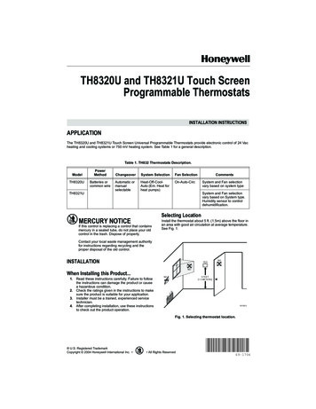
TH8320U AND TH8321U TOUCH SCREEN PROGRAMMABLE Y221RW2S1S2C3RCRWYGC21RCOPTIONAL24 IES 20MOTOR ORVALVE1POWER SUPPLY. PROVIDE DISCONNECT MEANS AND OVERLOADPROTECTION AS REQUIRED.2FACTORY INSTALLED JUMPER.3OPTIONAL OUTDOOR OR INDOOR REMOTE SENSOR. AVAILABLEON SELECT MODELS. WIRES MUST HAVE A CABLE SEPARATEFROM THE THERMOSTAT CABLE.COMPRESSORCONTACTOR1POWER SUPPLY. PROVIDE DISCONNECT MEANS AND OVERLOADPROTECTION AS REQUIRED.2FACTORY INSTALLED JUMPER.3OPTIONAL OUTDOOR OR INDOOR REMOTE SENSOR. AVAILABLEON SELECT MODELS. WIRES MUST HAVE A CABLE SEPARATEFROM THE THERMOSTAT CABLE.M19900M19899Fig. 10. Typical hookup of cool only system(1C conventional).Fig. 9. Typical hookup of heat only Series 20 RESENSORHEAT RELAY 21RRCRWYGCC2OPTIONAL 24 VACCOMMON CONNECTIONMUST COME FROMTHE COOLINGTRANSFORMER.FAN RELAYCOOL RELAY 2COOL RELAY 1HEAT RELAY 11POWER SUPPLY. PROVIDE DISCONNECT MEANS AND OVERLOAD PROTECTION AS REQUIRED.2FACTORY INSTALLED JUMPER.3OPTIONAL OUTDOOR OR INDOOR REMOTE SENSOR. AVAILABLE ON SELECT MODELS. WIRES MUSTHAVE A CABLE SEPARATE FROM THE THERMOSTAT CABLE.M19901Fig. 11. Typical hookup of conventional multistage two-stage heating and two-stage coolingin a single transformer system (2H/2C or 2H/1C or 1H/2C conventional).69-17064
TH8320U AND TH8321U TOUCH SCREEN PROGRAMMABLE L 24 VACCOMMON CONNECTIONMUST COME FROMTHE COOLINGTRANSFORMER.FAN RELAYOUTDOOR/INDOORTEMPERATURESENSORCOOL RELAY 2HEAT RELAY 21RCOOL RELAY 1CHEAT RELAY 11POWER SUPPLY. PROVIDE DISCONNECT MEANS AND OVERLOAD PROTECTION AS REQUIRED.2FACTORY INSTALLED JUMPER REMOVED.3OPTIONAL OUTDOOR OR INDOOR REMOTE SENSOR. AVAILABLE ON SELECT MODELS. WIRES MUST HAVE A CABLSEPARATE FROM THE THERMOSTAT CABLE.M19902Fig. 12. Typical hookup of conventional multistage two-stage heating and two-stage coolingin a two-transformer system (2H/2C or 2H/1C or 1H/2C conventional).HEAT PUMP1RY2LEAUXSIS24RCRO/BYGC2C3OPTIONAL 24 VACCOMMON CONNECTIONFAN ECOMPRESSOR1 POWER SUPPLY. PROVIDE DISCONNECT MEANS AND OVERLOAD PROTECTION AS REQUIRED.2 FACTORY INSTALLED JUMPER.3 "O/B" TERMINAL SET TO CONTROL AS EITHER "O" OR "B" IN THE INSTALLER SETUP.4 OPTIONAL OUTDOOR OR INDOOR REMOTE SENSOR. AVAILABLE ON SELECT MODELS. WIRES MUST HAVE A CABLE SEPARATEM19903FROM THE THERMOSTAT CABLE.Fig. 13. Typical hookup of single-stage heat pump with no auxiliary/backup heat (1H/1C heat pump).569-1706
TH8320U AND TH8321U TOUCH SCREEN PROGRAMMABLE THERMOSTATSHEAT PUMP1RY23LEAUXSIS2C4OPTIONAL 24 VACCOMMON CONNECTIONFAN NGEOVERVALVECOMPRESSOR 2COMPRESSOR 11 POWER SUPPLY. PROVIDE DISCONNECT MEANS AND OVERLOAD PROTECTION AS REQUIRED.2 FACTORY INSTALLED JUMPER.3 MUST CONNECT THE 24 VAC COMMON WHEN USING L. THE TERMINAL IS SHOWN AS EQUIPMENT MONITOR, CAN ALSO BE USED AS A 24 VACOUTPUT. SEE "L TERMINAL" SECTION FOR MORE INFORMATION.4 "O/B" TERMINAL SET TO CONTROL AS EITHER "O" OR "B" IN THE INSTALLER SETUP.5 OPTIONAL OUTDOOR OR INDOOR REMOTE SENSOR. AVAILABLE ON SELECT MODELS. WIRES MUST HAVE A CABLE SEPARATE FROM THETHERMOSTAT CABLE.M19904Fig. 14. Typical hookup of multistage heat pump with no auxiliary/backup heat (2H/2C heat pump).EQUIPMENTMONITORHEAT PUMP1R534CY2LEAUXSIS22RO/BYGCOPTIONAL 24 VACCOMMON CONNECTIONFAN RELAYOUTDOOR/INDOORTEMPERATURESENSORHEAT 2 RELAY(AUXILIARY HEAT)6CHANGEOVERVALVEEMERGENCYHEAT RELAYCOMPRESSORRELAY1 POWER SUPPLY. PROVIDE DISCONNECT MEANS AND OVERLOAD PROTECTION AS REQUIRED.2 FACTORY INSTALLED JUMPER.3 OUTDOOR SENSOR REQUIRED IN SYSTEM WITH FOSSIL FUEL BACKUP HEAT THAT IS NOT USING AN EXTERNAL FOSSIL FUEL KIT.4 OPTIONAL OUTDOOR OR INDOOR REMOTE SENSOR. AVAILABLE ON SELECT MODELS. WIRES MUST HAVE A CABLE SEPARATEFROM THE THERMOSTAT CABLE.5 MUST CONNECT THE 24 VAC COMMON WHEN USING L. THE TERMINAL IS SHOWN AS EQUIPMENT MONITOR, CAN ALSO BE USED ASA 24 VAC OUTPUT. SEE "L TERMINAL" SECTION FOR MORE INFORMATION.6 "O/B" TERMINAL SET TO CONTROL AS EITHER "O" OR "B" IN THE INSTALLER SETUP.M19905Fig. 15. Typical hookup of single-stage heat pump with auxiliary/backup heat (2H/1C heat pump).69-17066
TH8320U AND TH8321U TOUCH SCREEN PROGRAMMABLE THERMOSTATSEQUIPMENTMONITORHEAT PUMP1RCY25LEAUXSIS2342RO/BYGCEMERGENCYHEAT RELAYOPTIONAL 24 VACCOMMON CONNECTIONFAN RELAYOUTDOOR/INDOORTEMPERATURESENSORHEAT 2 RELAY(AUXILIARY HEAT)6CHANGEOVERVALVECOMPRESSOR 2COMPRESSOR 11 POWER SUPPLY. PROVIDE DISCONNECT MEANS AND OVERLOAD PROTECTION AS REQUIRED.2 FACTORY INSTALLED JUMPER.3 OUTDOOR SENSOR REQUIRED IN SYSTEM WITH FOSSIL FUEL BACKUP HEAT THAT IS NOT USING AN EXTERNAL FOSSIL FUEL KIT.4 OPTIONAL OUTDOOR OR INDOOR REMOTE SENSOR. AVAILABLE ON SELECT MODELS. WIRES MUST HAVE A CABLE SEPARATEFROM THE THERMOSTAT CABLE.5 MUST CONNECT THE 24 VAC COMMON WHEN USING L. THE TERMINAL IS SHOWN AS EQUIPMENT MONITOR, CAN ALSO BE USED ASA 24 VAC OUTPUT. SEE "L TERMINAL" SECTION FOR MORE INFORMATION.6 "O/B" TERMINAL SET TO CONTROL AS EITHER "O" OR "B" IN THE INSTALLER SETUP.M19906Fig. 16. Typical hookup of multistage heat pump with auxiliary/backup heat (3H/2C heat pump).Powering the ThermostatThere are two different ways to power the thermostat: Batteries (three AAA alkaline). 24 Vac Common wire.Wiring 24 Vac CommonWire the common side of the transformer to the C screwof the thermostat wallplate. When installing in a singletransformer system, keep jumper wire between the Rand Rc screws. When installed in a two-transformersystem, use the common from the cooling transformer toconnect to C screw and remove the jumper wire betweenthe R and Rc screws.Inserting Batteries (Optional)BATTERIES (3)If not using a 24 Vac Common to power the thermostat,install three AAA alkaline batteries (included) in the backof the thermostat. Make sure the positive and negativeterminals are oriented correctly, as marked on the device.See Fig.17.M19918Fig. 17. Installing batteries on thermostat back.Mounting the Thermostat1.2.7Align the terminal screw blocks with the pins on theback of the thermostat.Push the thermostat straight onto the wallplate.See Fig. 18.69-1706
TH8320U AND TH8321U TOUCH SCREEN PROGRAMMABLE THERMOSTATSWALLSET CURRENT DAYSET MONTHMONTUEWEDDTHUFRIRISATATSUNDONEREMOVE DURINGINSTALLATIONUSE ARROWS TO SET YEAR AND TIMEM19919MONWEDWTHUFRISATATSUNOK TO PICK MULTIPLEUDAYS SCREEN LOCKEDCHANGE FILTERR UV LAMP HUMIDIFIER PADFig. 18. Mounting thermostat on wallplate.Adjusting Real-Time ClockDONESetting Calendar and TimeLocate and remove the tab labeled Remove in the lowerleft corner on the thermostat back. The tab must beremoved to activate the real-time clock. See Fig. 19.M19921Fig. 20. Setting calendar and time after initialpowerup.REMOVE TAB TO ACTIVATE REAL TIME CLOCKREMOVE DURINGINSTALLATIONIMPORTANTThe tab on the back of the thermostat in thelower left corner must be removed for thisfeature to be active.Using the ThermostatREMOVE DURINGINSTALLATIONThe thermostat has a touch screen interface. Words orsymbols appear, highlighting the keys, as necessary, tocomplete tasks. Always press the keys with your fingertips. Sharp instruments like a pen or pencil point candamage the thermostat.1.M199202.3.Fig. 19. Removing tab to activate real-time clock.This thermostat is designed to automatically keep thecurrent time and day in memory for up to ten years undernormal use once the calendar is set. When thethermostat is first powered, the display is ready for thecalendar date to be entered. See Fig. 20.69-17064.8Use the arrow keys to set the Year, Month and Day,as shown in Fig. 20.Press the Done key.Use the arrow keys to set the current time. SeeFig. 20.Press the Done key.
TH8320U AND TH8321U TOUCH SCREEN PROGRAMMABLE THERMOSTATSOPERATIONINSTALLER SETUPSystem and Fan SettingsThis Universal Thermostat works with many differentsystem types. To operate correctly, the thermostat mustbe set up to operate the installed heating and/or coolingsystem.The System default setting is Heat and the Fan defaultsetting is Auto.SYSTEM SETTINGSHeat: Thermostat controls heating system.Off: Both heating and cooling are off.Cool: Thermostat controls cooling system.Auto: Thermostat automatically changes betweenheating and cooling systems, depending on indoortemperature. (See Installer Setup section.)Em Heat: Emergency heat cycles to maintaintemperature. Compressor is locked out. (Used only forheat pump systems with backup heat.)Installer Setup MenusMain Menu: Offers the most commonly used options.It is necessary to enter this menu to set thethermostat to the type of system it is operating. Manyapplications use only the Main Menu.Regional Menu: Offers choices often changed due to aparticular area or region. For example, temperaturedisplay in Fahrenheit or Celsius is offered in this menu.FAN SETTINGSThe Fan setting can be programmed into the thermostatschedule for each period (Wake, Leave, Return, Sleep).See the Owners’ Guide for additional information.Advanced Settings Menu: Offers more settings to fullycustomize the thermostat. Many of these settings do notrequire changing from the factory settings.Entering Installer SetupLED Indication (Requires 24 Vac CommonConnection)1.2.An LED indicator is located in the upper right corner ofthe thermostat. It is only visible when lighted: It indicates when the thermostat is in the EmergencyHeat mode. When in Em. Ht. mode, the L terminal iscontinuously energized and the LED is on. When the L terminal is wired to an equipment monitor,the LED signals when a check or fail signal is sent tothe thermostat from the system. See Fig. 21. (Thiscan occur only when the thermostat is not in Em. Ht.mode.)3.Thermostat must be powered either with AlkalineAAA batteries or with 24 Vac Common wire.From the home screen, press System key. (PressDone or Cancel key to return to home screen.)Five blank touch keys show on the bottom of thescreen between the Done and Cancel keys. Pressand hold the two blank keys on either side of thecenter blank key for approximately five secondsuntil screen changes. See Fig. 22.TO CCMONTUEWEDInsideEQUIPMENTMONITORLTO RSYSTEMEM HEATM19907OFFCOOLFig. 21. L terminal switch to R (power) side of systemtransformer.DONETHUFRISATATSUNSet ToFollowingSchedulePMCANCELPreprogrammed SettingsTable 3 shows the default program settings. See Owners’Guide for complete instructions on changing theprogram.M19923Table 3. Default Program Settings.SchedulePeriodSetpointsTimeHeatCoolFig. 22. Entering Installer Setup.FanSettingWake6:00AM70 F(21 C)78 F(25.5 C)AutoLeave8:00AM62 F(16.50C)85 F(29.50C)AutoReturn6:00PM70 F(21 C)78 F(25.5 C)AutoSleep10:00PM 62 F(16.5 C)82 F(28 C)Auto969-1706
TH8320U AND TH8321U TOUCH SCREEN PROGRAMMABLE THERMOSTATS4.Changing Installer Setup SelectionsThe Installer Setup Number is displayed in thelower left. It is a four-digit code beginning with zero.The factory setting or other choice selection is displayed in the lower right. See Fig. 23. This is a twodigit code shown in the Option column of Table 4.1.Advance to the next Installer Setup Number bypressing the up and down arrow keys to the right ofthe four-digit Installer Setup Number. See Fig. 23.Change the factory Setting Options by pressing theup and down arrow keys to the right of the two-digitcode selection. See Fig. 23.2.ADVANCE TO NEXTINSTALLER SETUPINSTALLERSETUP NUMBERExiting Installer SetupFACTORYSETTING1.WEDMONTHUUFRISATATPress the Done key to exit the Installer Setupscreen.IMPORTANTThe three Installer Setup Menus (Tables 4-6)show all the available options. These optionscustomize themselves as you make selectionsto the Installer Setup. Therefore, not all InstallerSetup Selections are shown or are available tochange.SUNDONEOCHANGE THEFACTORYSETTINGPRESS TO EXITINSTALLER SETUPM19922Fig. 23. Installer Setup Number and factory settingselection locations.Table 4. Main Installer Setup Menu.Factory SettingSelectInstallerSetupNumberOptionOther ChoicesDescriptionNot used.1 thru 0099 ——Date (YearUpper)012020Date (YearLower)0130Date (Month)OptionsDescriptionComments——Set first two digits of21current calendar year(20 for year 2005, etc)21 —first two digits ofcurrent calendar year(21xx)2000 -2178available04Represents last twodigits of currentcalendar year (2004).00 -99Select last two digits ofcurrent calendar year.2001-2178available01406Digit(s) representscurrent calendarmonth.1-12Select number thatrepresents currentcalendar month.—Date(Day)015015Digit(s) represents1-31current calendar date.Select number thatrepresents currentcalendar date.—ScheduleOptions016047-day programming0 —nonprogrammable—69-1706—100
TH8320U AND TH8321U TOUCH SCREEN PROGRAMMABLE THERMOSTATSTable 4. Main Installer Setup Menu. (Continued)Factory ts1—1heat/1cool2—single-stage heatpump (no aux. heat)3—heat only (no fan)4—heat only (with fan)5—hot water Series 20(3-wire or normally openzone valves)6—cool only7—2 heat/1cool heatpump8—2 heat/2 coolmultistage conventional9—2 heat/1coolmultistage conventional10—1 heat/2 coolmultistage conventional11—2 heat/2 cool heatpump (with no auxiliaryheat)12—3 heat/2 cool heatpump (with auxiliary heat)Availableoptions anddefaults varyby thermostat. Systemselectionautomaticallymodifiessome defaultsettings and/or hides otherInstaller Setup options.Conventional1applications whereequipment controls fanoperation in heatmode.Heat pump or electricheat applications wherethermostat controls fanoperation in heat mode.Only shown ifconventionalsystem isselected. Ifheat pump ischosen, fandefaults toelectric.0O/B terminal is1energized for reversingvalve in coolingO/B terminal is energized Only shown iffor reversing valve inheat pumpheatingsystem ischosen.02000Heat pump backup1heat source is electric.Heat pump backup heatsource is fossil fuel.Only shown if2 heat/1 coolor 3 heat/2cool heatpump ischosen.External Fossil 0210Fuel Kit1External fossil fuel kitis controlling heatpump backup heat0No external fossi
Š Radiant heat from sun or appliances. Š Concealed pipes and chimneys. Š Unheated (uncooled) areas such as an outside wall behind the thermostat. Installing Wallplate CAUTION Electrical Hazard. Can cause electrical shock or equipment damage. Disconnect power before wirin