Transcription
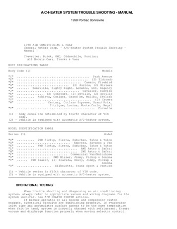
Blower Application BasicsBlower Application Basics:Figure 1: Typical System Resistance Curve - Pressure Drop vs. Flow RateSystem Resistance Curve: A resistance to flow is typically characterizedby a pressure drop for a given flow rate,and often follows a 2nd order relationship (see Figure 1) (in some cases suchas certain filters, the relationship ismore linear). If the desired operatingpoint is known, then its associated system curve can be estimated accordingto the relationship P CQ2. Plugging thevalues for desired operating point intothe P (pressure drop) and Q (flow rate)terms yields the constant C. The system curve can then be overlaid graphically onto a given blower performancecurve. The intersection of the twocurves is the actual operating point (seeFigure 2). The pressure rise providedby the blower matches the pressureloss imposed by the system resistance.For quick checks, simply place the operating point on a given blower curveand “eyeball” the system curve throughit.There are likely to be several models that can achieve the desired performance, but not all will operate with thesame efficiency. The blower performance curves in this catalog include notonly pressure vs. flow rate information,but also current and input power vs.flow rate. An application is normally5Pressure Drop43P CQ2P - pressure DropQ - flow rateC - constant for given system2100123Flow RateFigure 2: System and Blower Curves - Identifying the Operating Point54Blower performance curvePressureSelecting a blower for a particularapplication first requires knowledge oran estimate of the application’s operating point: the flow rate required and theresistance to flow that the system, ductwork, filters, obstructions, etc., will impose. This system resistance is oftenreferred to as backpressure or headloss. The performance curves shown inthis catalog represent each model’s typical maximum performance (full speed)at a constant input voltage. The performance curve describes a blower’s ability to deliver flow rate againstbackpressure - from zero backpressure(“open flow”) to completely blocked flow(“sealed”). Since all Ametek BLDCblowers have adjustable speed control,any operating point that lies underneatha given performance curve can bereached. With knowledge of the desired operating point, it is then a simplematter to browse the catalog to identifyblowers having performance curvesthat exceed the desired operating point.Other factors should then be considered, which will be discussed hereafter.3Actual operating point21Desired operating pointSystem curve00123Flow Rate Does my application require modulating the speed during operation, orsimply a single speed adjustment madeat the time of installation? What input voltage will I have available for powering the blower? Are there additional features that Irequire such as a tachometer output,dynamic braking, or speed control functions? Will a blower of this size fit in my Is it a problem for the working fluidto come into contact with electronics?application? Would I prefer that the blower have What are the environmental factorsan on-board controller or would I prefer associated with my application?to provide an external controller? Do I need a blower with fast dy- Blower Performance vs. SpeedChanges: Since Ametek’s blowers arenamic response?speed controllable, the speed can be Is loudness a major factor?reduced to a desired operating point orbest served by selecting the blower thatdelivers the desired performance withthe least amount of input power. Typically, the most efficient blower is theone where the system resistance curveintersects the blower curve at approximately the middle, i.e., half the maximum flow rate.Other questions to consider whenselecting a blower:This document is for informational purposes only and should not be considered as a binding description of the products or their performance in all applications. The performance data on this page depictstypical performance under controlled laboratory conditions. AMETEK is not responsible for blowers driven beyond factory specified speed, temperature, pressure, flow or without proper alignment. Actualperformance will vary depending on the operating environment and application. AMETEK products are not designed for and should not be used in medical life support applications. AMETEK reserves theright to revise its products without notification. The above characteristics represent standard products. For product designed to meet specific applications, contact AMETEK Technical & Industrial ProductsSales department.AMETEK TECHNICAL & INDUSTRIAL PRODUCTS627 Lake Street, Kent OH 44240USA: 1 215-256-6601 - Europe: 44 (0) 845 366 9664 - Asia: 86 21 5763 1258www.ametektip.comF1PRECISION MOTION CONTROL
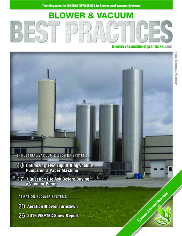
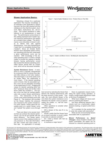
Blower Application Basicsincreased if a different operating point isneeded in a dynamic system. Blowersconveniently have very predictable behavior when it comes to changes inspeed. Table 1 summarizes these relationships.H2O. The blower whose performance isshown in Figure 3 has been chosen.What will be the power consumption at8 cfm, 6 in H2O?Answer: At full speed, the blower willdeliver about 8.8 cfm in this system,whose backpressure is about 7.2 inH2O at that flow rate (see Figure 3).Since this is delivering too much, thespeed must be reduced to achieve thedesired operating point.Gage Pressure vs. Absolute Pressure:Before proceeding, it’s important at thispoint to note that this tutorial makes reference to both “absolute pressure” and“gage pressure.” Gage pressure is simplythe difference above or below atmospheric (or barometric) pressure. Absolute pressure is the sum of atmosphericand gage pressures:Table 1: Fan Laws Related toChanges in Blower SpeedAt full speed, Figure 3 shows the blowerspeed to be about 19.8 krpm and thepower consumption is 18.3 W. Usingthe fan laws shown in Table 1 yields:( NN )Nm m ( )NNP P ( )N ( NN )2Q2 Q118 cfm 8.8 cfm22Pabsolute Pgage Patm11( 19.8Nkrpm )2N2 18.0 krpm222Pressure values stated hereafter aregage values unless otherwise stated.11So, the power consumption at the reduced speed is:32Figure 3 with Example 1 demonstrateshow to calculate the power requirementfor an operating point that occurs at areduced speed.Example 1:An application calls for air performanceof 8 cfm (ft3/min) at a pressure of 6 inch211Where,N mQPfan rotational speedmass flow ratevolume flow ratestatic pressure (gage)blower power demandAll other variables constant.2 18.3 W2(18.0 krpm19.8 krpm3) 13.7 W122411221020918816714612510483Input Power (W)Speed (krpm)Pressure (in H 2O)Figure 3: Speed Change Calculation Example6blower pressure vs. flow24blower input power vs. flowblower speed vs. flowsystem resistance1200024681012141618Flow Rate (cfm )This document is for informational purposes only and should not be considered as a binding description of the products or their performance in all applications. The performance data on this page depictstypical performance under controlled laboratory conditions. AMETEK is not responsible for blowers driven beyond factory specified speed, temperature, pressure, flow or without proper alignment. Actualperformance will vary depending on the operating environment and application. AMETEK products are not designed for and should not be used in medical life support applications. AMETEK reserves theright to revise its products without notification. The above characteristics represent standard products. For product designed to meet specific applications, contact AMETEK Technical & Industrial ProductsSales department.AMETEK TECHNICAL & INDUSTRIAL PRODUCTS627 Lake Street, Kent OH 44240USA: 1 215-256-6601 - Europe: 44 (0) 845 366 9664 - Asia: 86 21 5763 1258www.ametektip.comF2PRECISION MOTION CONTROL
Blower Application BasicsThe speed at the desired operating sure, thereby increasing the blower’spoint could also have been found by ability to provide flow against backpresusing the ratio of pressures:sure, but this is not a common practice.(6 in H2O 7.2 in H2ON22)19.8 krpmNote: There is some minor error in thiscalculation because there will likely besome small change in motor efficiencyat the different operating point. Thiscan usually be neglected for estimatingpower requirements.Static and Velocity Pressure: Theenergy of a fluid can be viewed as having two types of pressure: static pressure and velocity pressure.Static pressure is the force per unitarea exerted by the fluid on its surroundings, and is independent of thefluid’s motion. This is the pressure thatwould be measured by a pressure sensor ported normal to the direction offlow. Dividing this pressure by the fluiddensity yields an energy term (per unitmass) often referred to as “pressurehead.”Velocity pressure is essentially thekinetic energy content, or velocity head,of the fluid. It is the pressure that wouldresult from slowing down the streamlinevelocity to zero, converting the kineticenergy into pressure head. Mathematically, it takes the form P ½ 2, wherevelocity (including the density valuemaintains force per area, i.e., pressureunits).The sum of the static pressure andvelocity pressure is the total pressure.Within a flow system, there are alsolikely to be changes in elevation(potential energy or elevation head) thatcontribute to the energy content of thestream at a given point. But thechanges in elevation head for gas floware usually small enough to be safelyignored.The blower performance curvesherein are plotted as static pressure (orvacuum) rise vs. flow rate. The velocitypressure is typically not a useful energyquantity for overcoming resistance toflow. In other words, in most cases theresistance to flow results in a loss ofstatic pressure of the streamline and notto a loss of velocity pressure. Technically, a diverging nozzle could be used toconvert velocity pressure to static pres-Fluid Density: The density of the working fluid has a significant influence onblower performance, as can be seen inthe relationships listed in Table 2. Because fluid density is a variable that isindependent of the blower, the densitymust be stated as part of any blowerperformance specification. In the previous example, the density was ignoredfor simplicity. But the performancecurves for all blowers in this cataloghave the statement “normalized to airdensity .075 lb/ft3,” or equivalentstatement. So, in the previous example, it was assumed that the desiredperformance of (8 cfm, 6 in H2O) hadalso been normalized to .075 lb/ft3.The density value of .075 lb/ft3 is asomewhat arbitrary selection, but it isclose to typical air density at sea level.It is commonly referred to as “StandardDensity” in the fan and blower industry.Any target operating point must be normalized to .075 lb/ft3 when evaluatingblower performance curves in this catalog. Examples hereafter demonstratehow to do this.The vast majority of blower applications are designed to move air, butAmetek blowers can be used with anynon-explosive, non-corrosive gas mixture (exception - see Ametek’s Nautilairseries for blowers designed for combustion pre-mix applications). Caution:most of the blowers in this catalog arenot designed to be leak-proof, andmany vent some working fluid to coolthe motor. At the temperature and pressure ranges for most blower applications, the gas mixture can beconsidered an ideal gas, and it will behave according to the relationship:Table 2: Fan Laws Related toChanges in Fluid Density:( ) ( )m m ( )2P2 P 112212112Where,P m1fluid densitystatic pressure (gage)power demandmass flow rateNote: volume flow rate, Q, is independentof density for gases.tures. Because of the difference inviscosity between air and other gases atthe same conditions, the blower performance curves herein will have someerror when evaluating non-air performance, even if the operating point isnormalized to standard density. Contact Ametek engineering for help in selecting a blower for non-air applications.Determining air density requiresknowing the temperature, barometricpressure, and humidity of the workingenvironment. Measuring temperatureis relatively easy, but barometric pressure requires a barometer, and humidityrequires either a wet bulb thermometer,a hygrometer, or a dew point detector.(Note: be careful if using barometricvalues obtained from weather services they are normalized for altitude andare not the actual barometric pressuremeasurements.Once these values are known, theeasiest way to determine density is toPMuse a psychrometric chart, which givesRuTthe properties of air for large ranges ofWhere, P is the absolute pressuretemperature and humidity. (There areis the densityalso on-line calculators available).Ru is the universal gas constantSome notes on using a psychrometricT is the absolute temperaturechart:M is the molar mass1) Instead of density, the specific volume, which is the reciprocal of density,For gas mixtures, the molar mass of the usually is plotted.mixture can be determined from the 2) The specific volume is typically givenweighted average of the component in terms of volume per unit mass of drygases. Refer to texts on thermodynam- air. But the working fluid is a mixture ofics or contact Ametek engineering for air and water vapor (except at 0% huhelp in calculating density for gas mix- midity, of course). See the exampleThis document is for informational purposes only and should not be considered as a binding description of the products or their performance in all applications. The performance data on this page depictstypical performance under controlled laboratory conditions. AMETEK is not responsible for blowers driven beyond factory specified speed, temperature, pressure, flow or without proper alignment. Actualperformance will vary depending on the operating environment and application. AMETEK products are not designed for and should not be used in medical life support applications. AMETEK reserves theright to revise its products without notification. The above characteristics represent standard products. For product designed to meet specific applications, contact AMETEK Technical & Industrial ProductsSales department.AMETEK TECHNICAL & INDUSTRIAL PRODUCTS627 Lake Street, Kent OH 44240USA: 1 215-256-6601 - Europe: 44 (0) 845 366 9664 - Asia: 86 21 5763 1258www.ametektip.comF3PRECISION MOTION CONTROL
Blower Application Basicshereafter for calculating the actual specific volume, i.e., volume per unit massof the air-water vapor mixture.3) Dry bulb temperature is simply thetemperature measured using a regularthermometer.4) For humidity, the wet bulb temperature can be used directly without havingto convert to another type of humidityquantity. As an alternative, relative humidity or humidity ratio can be used.5) Psychrometric charts are plotted ata single barometric pressure which isnoted in the heading of the chart. Acorrection is needed to adjust densityvalues to the actual barometric pressure.reference texts and internet sites) givesa good estimate for typical outdoor ambient conditions as a function of altitude.The following example demonstrateshow to account for the lower density athigh altitude:Example 3: An application calls for ablower to deliver 50 cfm of air at 30 inch.075 lb/ft3H2O at an altitude of 7000 ft above seam2 3.10 lb/min.062 lb/ft3level where the average air density is0.062 lb/ft3, according to the Standardm2 3.75 lb/minAtmosphere Table. For the purpose ofselecting a blower from this catalog,Mass flow rate is directly proportional towhat operating point should be used?achange in speed (Table 1), so toAnswer: Refer to Table 2. Since vol3ume flow rate does not change with maintain 3.1 lb/ft , the speed must bereducedby:density, the flow rate remains at 50 cfm.(Example 2: A laboratory makes the The pressure does change in proportionfollowing measurements of the ambient to density:air conditions:Barometric pressure 28.60 in HgDry bulb temperature 72 oFWet bulb temperature 65 oFWhat is the ambient density?Answer: Using a psychrometric chartplotted at 29.921 in Hg, the intersections of the curves corresponding to thedry bulb and wet bulb values aboveyields a specific volume of 13.64 ft3/lbdryair and a humidity ratio of .0116 lbwatervapor per lbair. Correct the specific volume per lb air-water vapor mixture:mwvmair .0116mmixture mwv mair .0116mair mair 1.0116mairP2 30 inch H2O3.10 lb/min 3.75 lb/min( NN )2.075 lb/ft3( .062 lb/ft )3( NN ) .827 17.3% reduction21P2 36.3 inch H2OB) Since volume flow rate is indepenSo, the operating point normalized to dent of density, the volume flow rate willstandard density is 50 cfm, 36.3 inch not change between the two locations ifthe speed remains constant. This illusH2O.trates the difference between the quanExample 3 continued: A blower is se- tities of volume flow and mass flow - alected from the catalog that can deliver factor that must be kept in mind whenthe above performance with a power evaluating an application’s air perfordemand of 600 W at standard density, mance needs.as shown on the published performancecurves. What will be the power demand C) Tables 1 and 2 show that the powerat the intended location at 7000 ft alti- demand is directly proportional to bothdensity and speed, although a speedtude?change has a much larger influence.Answer: Refer to Table 2 for correcting Combining both relationships yields:power demand for a change in density.lb/ft( .062.075 lb/ft )32 600 W2 496 W)N2N1 12 13( )( ).075 lb/ft(.062) (.827)lb/ft223Finally, correcting this value for the ac- Example 3 continued - Redefining thetual barometric pressure yields:problem in terms of mass flow rate: Theapplication requires a mass flow rate of3.1 lb/min of air regardless of altitude.29.921 in Hg13.49 ft3/lbmixA)How much must the speed be re28.60 in Hgduced if the application is moved from a 14.12 ft3/lbmixlocation at 7000 ft (.062 lb/ft3) to sealevel (.075 lb/ft3)? .0708 lbmix/ft3B) If the speed is not adjusted to compensate for the change is density, whatwill be the change in volume flow rateThe density of air varies substan- between the two locations?tially with weather and altitude. The C) How much will the power demandStandard Atmosphere Table (not in- change?cluded herein, but widely available in()1mair .989mmix.989(13.64 ft3/lbair) 13.49 ft3/lbmixAnswer:A) Table 2 shows that the change inmass flow rate is a simple ratio of thedensities. If the blower speed is maintained between the two locations, themass flow rate delivered at sea level willbe:13332 .6841 31.6% reductionIncompressible Flow: Although thedensity of the working fluid is a variablethat must be accounted for, in a givenapplication the density is assumed to beconstant for applications involving theblowers herein. In other words, for agiven blower in operation the fluid entering the blower has the same density asthe fluid leaving the blower. Anotherterm for this is “incompressible flow.”Density variations are less than oneThis document is for informational purposes only and should not be considered as a binding description of the products or their performance in all applications. The performance data on this page depictstypical performance under controlled laboratory conditions. AMETEK is not responsible for blowers driven beyond factory specified speed, temperature, pressure, flow or without proper alignment. Actualperformance will vary depending on the operating environment and application. AMETEK products are not designed for and should not be used in medical life support applications. AMETEK reserves theright to revise its products without notification. The above characteristics represent standard products. For product designed to meet specific applications, contact AMETEK Technical & Industrial ProductsSales department.AMETEK TECHNICAL & INDUSTRIAL PRODUCTS627 Lake Street, Kent OH 44240USA: 1 215-256-6601 - Europe: 44 (0) 845 366 9664 - Asia: 86 21 5763 1258www.ametektip.comF4PRECISION MOTION CONTROL
Blower Application Basicspercent for flow speeds less than Mach vapor is not a problem as long as it doesTHE FAILURE TO OBSERVE THE 0.2, which is greater than typical ap- not condense into liquid water inside the FOLLOWING SAFETY PRECAUplications for these blowers.blower.TIONS COULD RESULT IN SERIOUSBODILY INJURY, INCLUDING DEATHBlower Life: Brushless DC blowers Mechanical Shock:MechanicalIN EXTREME CASES. We recommendhave the advantage of long life com- shock can cause denting of the that adequate instructions and warningspared to blowers driven by brush mo- bearing’s rolling elements. This results by the original equipment manufacturtors. Since the motor is electronically in unwanted noise and can lead to flak- ers (OEM) include labels setting forthcommutated there are no brushes to ing and pitting inside the bearing. Appli- the precautions listed below to the endwear out, so the end of life scenario for cations that subject the blower to user.brushless blowers is normally bearing mechanical shock should be thoroughlyThe motors and/or blowers must befailure.tested to ensure adequate life.connected to a proper and effectiveSince long life is one of the mainground or mounted in a manner that willattributes of brushless technology, the Operating point: The amount of back- guarantee electrical isolation and insuquestion “How long will it last?” is com- pressure a blower works against is an- late the user and others from electricmon. Unfortunately, there is no simple other influencing factor in some blower shock. End product design should notanswer to this question. There are a models. The backpressure results in a rely solely on the primary insulation ofnumber of factors that influence life, and pressurized blower housing, putting a the motor.we currently have no way to account for pressure gradient across the adjacentStandard blowers and/or motorsevery possible application. The primary bearing. The pressure gradient tends to are not designed to handle volatile orfactors that influence life are:push the grease out and contamination flammable materials through the fanin. Ametek has implemented design system unless specifically designed. temperaturefeatures to minimize this effect, and the Passing combustible gases or other bearing contaminationcustomer should not be hesitant to op- flammable materials through the fan mechanical shockerate at high pressure if the application system could result in leakage which operating pointcalls for it.could cause a fire or explosion.These products must not be used inTemperature:The deterioration ofAgain, blower life is highly applica- an area contaminated by volatile orbearing grease is directly proportional tion dependent. Customer requests for flammable materials since sparking isto its temperature. So, the higher the MTTF (Mean Time To Failure) informa- predictable in the normal operation oftemperature, the shorter the bearing tion are difficult to answer. Moreover, the motor and may ignite the volatilelife. There is no hard limit on bearing what constitutes a failure is often open causing a dangerous explosion.temperature, but just a general rule that to interpretation. For example, thereThe Technical and Industrial Prodcooler is better. There is a point of can be situations where a blower is ucts Division of Ametek, Inc. can supplydiminishing returns that is application delivering air performance as required, specifically designed motors and blowdependent - reducing temperature is but it has deteriorated bearings that ers for use in handling combustibleunnecessary if the blower life is ade- produce unacceptable noise for sound- gases or for use in hazardous dutyquate for the application. A rule of critical applications.locations. These specially designedthumb for Ametek blowers is 45 oCAmetek does conduct an ongoing units should only be used in conjunctionmaximum ambient temperature, but this life test program to gather life informa- with combustible gases, which theycan be exceeded under certain circum- tion and to improve the durability of our were specifically designed to handle.stances. Please consult Ametek engi- blowers. Tests are conducted on blow- The type of gases must be so noted onneering for applications a high ers that represent all model families. the product label and in the instructions.temperatures. Ultimately, it is up to the History has shown that Ametek blowersThe rotation of the motor shaft, orcustomer to determine whether or not a survive beyond 10,000 hours of contin- anything mounted on the shaft, is ablower can provide adequate life. Thor- uous running in typical applications. It potential source of injury and must beough testing is recommended. Also is common for blowers to endure more taken into account in the design of yourkeep in mind that extreme temperature than 20,000 hours, and some blowers end product. You must provide thecan cause premature failure of electron- have accumulated 30,000 hours. But necessary guarding or housing as reics or the motor winding.again, it must be stressed that blower quired by the finished product and youlife is application dependent, and the must indicate to the user the direction ofBearing Contamination: The introduc- customer is encouraged to conduct a rotation. Do not remove guard as setion of particulate matter increases the life test in-situ under the application’s vere bodily injury may occur to fingersrolling friction of the bearing, which in- most rigorous conditions. The life val- or appendages.creases temperature. Particulates also ues mentioned above are not to beProducts incorporating vacuumscar the surface of the bearing race- used as a basis for warranty claims.motors/blowers must be designed so asto prevent the vacuum or air pressureways and balls, which increases pittingIn the applica- from being concentrated in a mannerand flaking, further exacerbating the Safety Bulletin:condition. Corrosive gases can react tion of Ametek, Inc. motors and/or blow- that can expose the user to injury bynegatively with grease or cause corro- ers as a component in your product, you coming into contact with any body area,sion of the steel in the bearings. Liquids must exercise the following minimum such as eyes, ears, mouth, etc.of any kind should be avoided. Water precautions:This document is for informational purposes only and should not be considered as a binding description of the products or their performance in all applications. The performance data on this page depictstypical performance under controlled laboratory conditions. AMETEK is not responsible for blowers driven beyond factory specified speed, temperature, pressure, flow or without proper alignment. Actualperformance will vary depending on the operating environment and application. AMETEK products are not designed for and should not be used in medical life support applications. AMETEK reserves theright to revise its products without notification. The above characteristics represent standard products. For product designed to meet specific applications, contact AMETEK Technical & Industrial ProductsSales department.AMETEK TECHNICAL & INDUSTRIAL PRODUCTS627 Lake Street, Kent OH 44240USA: 1 215-256-6601 - Europe: 44 (0) 845 366 9664 - Asia: 86 21 5763 1258www.ametektip.comF5PRECISION MOTION CONTROL
Blower Application BasicsUnit ConversionsLength: 1 ft Density: 1 lbm/ft3 16.03 kg/m3 .01602 g/cm312 inch.3048 m30.48 cm.0001894 mileEnergy: 1 IW OEf 1.356 J 1.356 1 P .001285 BtuVolume: 1 ft3 .02832 m3 28.32 L 7.481 galPower: 1 W .00134 hp 3.413 Btu/hr 550 (ft-lbf)/sMass: 1 lbm .4536 kgForce: 1 lbfTemperature: T (oR) T(oF) 459.7 1.8[T(oC 273.15] 1.8T(K) 32.174 lbm IW V2 4.448 NVolume Flow Rate: 1 cfm (ft3/min) 28.32 L/min 1.699 m3/hrUniversal Gas Constant, Ru:Pressure: 1 inch H2O .249 kPa 2.49 mbar .0361 psi ( l b f /in 2 ) .0735 inch HgThe motors and/or blowers mustnot be exposed to moisture or liquid orused outdoors, except in equipmentwhich is specifically designed for outdoor use and meets the appropriateregulatory agency requirements for outdoor use. Moisture or liquid can damage the motor/blower and defeat theelectrical insulation resulting in a severeelectrical shock to the user.Ametek motors/blowers must notbe operated above the design voltage.Over voltage conditions can cause excessive speed of the motor and canresult in severe electrical shock and/orother traumatic injury to the operator.Precautions must be exercised toensure motor leads are properly routedand connected in your equipment.Lead wires must be routed and retainedto ensure that they do not becomepinched or come in contact with rotatingparts during assembly or subsequentoperations. Connections must be designed so that proper electrical contactis established and the connections mustbe properly insulated.Disassembly or repairs of Ametekproducts should not be attempted. Ifaccomplished incorrectly, repairs cancreate an electrical shock and/or operational hazard. It is recommended thatrepairs be made only by Ametek andnot by others.In the event that the motor orblower ceases to operate, power must 10.73 psia IW3/(lbmoO oR) 1545 ft lbf/(lbmoO oR) 8.314 kJ/(kgmol K) 8.314 kPa P3/(kgmoO .be disconnected before examinationand/or removal from the system.Contact Ametek, Inc. to discuss anyquestionable application before selecting a standard motor or blower.In setting forth the above listedrecommendations with regards to precautionary steps that must be considered, we in no way intend to imply thatif these steps are taken a product willmeet the applicable safety standards.We, at Ametek, are not sufficiently conversant with the specific safety hazardswhich may be associated with particularproducts. We can only advise precautions to be employed generally for thesafe use of Ametek products as components. For testing specifically related tothe safety of the product, we recommend that you contact the appropriateregulatory agency as indicated by thetype of product being manufac
have the statement "normalized to air density .075 lb/ft 3," or equivalent statement. So, in the previous exam-ple, it was assumed that the desired performance of (8 cfm, 6 in H 2O) had also been normalized to .075 lb/ft 3. The density value of.075 lb/ft 3 is a somewhat arbitrary selection, but it is close to typical air density at sea level.