Transcription
Minneapolis Blower Door Operation ManualforModel 3 and Model 4 SystemsENERGYCONSERVATORYTheDIAGNOSTIC TOOLS TO MEASURE BUILDING PERFORMANCE
Minneapolis Blower Door Operation ManualforModel 3 and Model 4 SystemsThe Energy Conservatory2801 21st Ave. S., Suite 160Minneapolis, MN 55407(612) 827-1117 (Ph)(612) 827-1051 (Fax)www.energyconservatory.comemail: info@energyconservatory.comMinneapolis Blower Door, TECTITE, Duct Mask and Automated Performance Testing (APT) System aretrademarks of The Energy Conservatory, Inc. Minneapolis Duct Blaster and TrueFlow Air Handler Flow Meterare registered trademarks of The Energy Conservatory, Inc.Windows and Microsoft Word are registered trademarks of Microsoft Corporation.
Manual Edition: August 2012. 2012 by The Energy Conservatory. All rights reserved.ENERGY CONSERVATORY WARRANTYEXPRESS LIMITED WARRANTY:Seller warrants that this product, under normal use and service as described in the operator’s manual, shall be free from defects inworkmanship and material for a period of 24 months, or such shorter length of time as may be specified in the operator’s manual, from thedate of shipment to the Customer.LIMITATION OF WARRANTY AND LIABILITY:This limited warranty set forth above is subject to the following exclusions:a)b)c)d)With respect to any repair services rendered, Seller warrants that the parts repaired or replaced will be free from defects inworkmanship and material, under normal use, for a period of 90 days from the date of shipment to the Purchaser.Seller does not provide any warranty on finished goods manufactured by others. Only the original manufacturer’s warranty applies.Unless specifically authorized in a separate writing, Seller makes no warranty with respect to, and shall have no liability inconnection with, any goods which are incorporated into other products or equipment by the Purchaser.All products returned under warranty shall be at the Purchaser’s risk of loss. The Purchaser is responsible for all shipping charges toreturn the product to The Energy Conservatory. The Energy Conservatory will be responsible for return standard ground shippingcharges. The Customer may request and pay for the added cost of expedited return shipping.The foregoing warranty is in lieu of all other warranties and is subject to the conditions and limitations stated herein. No other express orimplied warranty IS PROVIDED, AND THE SELLER DISCLAIMS ANY IMPLIED WARRANTY OF FITNESS for particular purpose ormerchantability.The exclusive remedy of the purchaser FOR ANY BREACH OF WARRANTY shall be the return of the product to the factory ordesignated location for repair or replacement, or, at the option of The Energy Conservatory, refund of the purchase price.The Energy Conservatory’s maximum liability for any and all losses, injuries or damages (regardless of whether such claims are based oncontract, negligence, strict liability or other tort) shall be the purchase price paid for the products. In no event shall the Seller be liable forany special, incidental or consequential damages. The Energy Conservatory shall not be responsible for installation, dismantling, reassemblyor reinstallation costs or charges. No action, regardless of form, may be brought against the Seller more than one year after the cause ofaction has accrued.The Customer is deemed to have accepted the terms of this Limitation of Warranty and Liability, which contains the complete and exclusivelimited warranty of the Seller. This Limitation of Warranty and Liability may not be amended or modified, nor may any of its terms bewaived except by a writing signed by an authorized representative of the Seller.TO ARRANGE A REPAIR: Please call The Energy Conservatory at 612-827-1117 before sending any product back for repair or to inquireabout warranty coverage. All products returned for repair should include a return shipping address, name and phone number of a contactperson concerning this repair, and the purchase date of the equipment.
Table of ContentsSAFETY INFORMATION1CHAPTER 12INTRODUCTION1.1 What is a Blower Door?21.2 Air Leakage Basics31.2.a Stack Effect:41.2.b Wind Pressure:41.2.c Point Source Exhaust or Supply Devices:41.2.d Duct Leakage to the Outside:41.2.e Door Closure Coupled with Forced Air Duct Systems:1.3 Common Air Leakage SitesCHAPTER 2SYSTEM COMPONENTS2.1 Blower Door Fan2.1.a Determining Fan Flow and Using the Flow Rings:2.2 Test Instrumentation (Pressure and Fan Flow Gauges)4477892.2.a DG-700 and DG-3 Digital Pressure Gauges:92.2.b Automated Performance Testing System :102.3 Fan Speed Controllers112.4 Adjustable Aluminum Door Frame112.5 TECTITE Blower Door Test Software122.5.a TECTITE Features:CHAPTER 3TESTING12INSTALLING THE BLOWER DOOR FOR DEPRESSURIZATION133.1 Door Frame and Panel Installation3.1.a Where To Install The Door Frame?3.1.b Installing the Aluminum Frame:1313133.2 Installing the Outside Building Pressure Tubing143.3 Installing the Blower Door Fan153.4 Attaching the Gauge Mounting Board153.5 Gauge Tubing Connections for Depressurization Testing163.5.a DG-700 Gauge:163.5.b DG-3 Gauge:163.5.c APT System:173.6 Electrical and Tubing Connections to the Fan173.6.a Electrical Connections:173.6.b Connecting Tubing to the Model 3 Fan:183.6.c Connecting Tubing to the Model 4 Fan:183.7 Fan Control Cable for Cruise Control18CHAPTER 4SETTING UP THE BUILDING FOR TESTING194.1 Adjustable Openings194.2 Combustion Appliance/Exhaust Devices194.3 Testing For New Construction20
CHAPTER 5CONDUCTING A BLOWER DOOR DEPRESSURIZATION TEST215.1 Choosing a Test Procedure215.2 Depressurization Test Procedures Using the DG-700215.3 Depressurization Test Procedures Using the DG-3245.4 Using the Can’t Reach 50 Factors (One-Point Tests)275.4.a Potential Errors In One-Point CFM50 Estimate from Using the CRF Factors:285.5 Unable to Reach a Target Building Pressure During a Multi-Point Test?295.6 Testing in Windy Weather295.7 Before Leaving the Building29CHAPTER 6BASIC TEST RESULTS6.1 Basic Airtightness Test Results30306.1.a Air Leakage at 50 Pascals:306.1.b Normalizing Air Leakage for the Size of the House:316.2 Optional Correction for Air Density326.3 Additional Test Result Options (requires use of TECTITE software)336.3.a Leakage Areas:336.3.b Estimated Natural Infiltration Rates:336.3.c Mechanical Ventilation Guideline:346.3.d Estimated Cost of Air Leakage:35CHAPTER 7PRESSURIZATION TESTING7.1 Gauge Set-Up For Pressurization Measurements36367.1.a DG-700 and DG-3 Gauges:367.1.b APT System:377.2 Fan Set-Up For Pressurization Measurements387.3 Optional Correction for Air Density38CHAPTER 8FINDING AIR LEAKS398.1 Using Your Hand398.2 Using a Chemical Smoke Puffer398.3 Using an Infrared Camera398.4 Diagnosing Series Leakage Paths40CHAPTER 9TESTING FOR DUCT LEAKAGE AND PRESSUREIMBALANCES9.1 Duct Leakage Basics9.1.a Why Is Duct Leakage Important?4141419.1.b Where Does Duct Leakage Occur?419.1.c How Much Can Energy Bills Be Reduced By Sealing Duct Leaks?429.1.d Duct Leakage to the Outside:429.1.e Duct Leakage to the Inside:9.2 Finding Duct Leaks to the Outside43439.2.a Smoke Test:439.2.b Pressure Pan:439.3 Estimating Duct Leakage to the Outside With a Blower Door9.3.a Modified Blower Door Subtraction:4444
9.3.b Flow Hood Method: (Requires use of calibrated flow capture hood)469.4 Unconditioned Spaces Containing Ductwork469.5 Testing for Pressure Imbalances Caused By Forced Air System Flows479.5.a Dominant Duct Leak Test:479.5.b Master Suite Door Closure:489.5.c All Interior Doors Closed:489.5.d Room to Room Pressures:9.6 Other Important Test Procedures49499.6 a Total System Air Flow:499.6.b System Charge:499.6.c Airflow Balancing:49CHAPTER 10COMBUSTION SAFETY TEST PROCEDURE5010.1 Overview5010.2 Test Procedures5110.2.a Measure Ambient CO Level in Building:5210.2.b Survey of Combustion Appliances:5210.2.c Survey of Exhaust Fans:5210.2.d Measure Worst Case Fan Depressurization:5210.2.e Spillage Test (natural draft and induced draft appliances):5410.2.f Carbon Monoxide Test:5510.2.g Draft Test (natural draft appliances):5510.2.h Heat Exchanger Integrity Test (Forced Air Only):55APPENDIX ACALIBRATION AND MAINTENANCEA.1 Fan Calibration Parameters (Updated January 2007)5757Model 3 (110V) Calibration Parameters:57Model 3 (230V) Calibration Parameters:57Model 4 (230V) Calibration Parameters:57A.2 Issues Affecting Fan Calibration58A.2.a Fan Sensor and Motor Position:58A.2.b Upstream Air Flow Conditions:60A.2.c Operating Under High Backpressure Conditions:A.3 Blower Door Fan Maintenance and SafetyA.3.a Maintenance Checks:606161A.3.b General Operational Notes and Tips:61A.3.c Replacing the Model 4 Controller’s Internal Fuse:61A.4 Calibration and Maintenance of Digital Pressure Gauges63A.4.a Digital Gauge Calibration:63A.4.b Digital Gauge Maintenance:64A.5 Checking for Leaky Tubing64APPENDIX BFLOW CONVERSION TABLES65Model 3 (110V)65Model 3 (230V)67Model 4 (230V)69
APPENDIX CUSING FLOW RINGS C, D AND EC.1 Using Ring C7171C.1.a Installation:71C.1.b Calibration Parameters for Ring C (Updated January 2007):71C.2 Using Rings D and E71C.2.a Installation:71C.2.b Measuring Fan Flow with Rings D and E:72C.2.c Calibration Parameters for Rings D and E (Updated January 2007):72APPENDIX DSAMPLE TEST FORMS74APPENDIX EHOME ENERGY ARTICLE *77APPENDIX FCALCULATING A DESIGN AIR INFILTRATION RATE83APPENDIX GREFERENCES85APPENDIX HAIR DENSITY CORRECTION FACTORS86H.1 Air Density Correction Factors for Depressurization Testing86H.2 Air Density Correction Factors for Pressurization Testing87APPENDIX ICRUISE CONTROL WITH THE DG-700 GAUGE88APPENDIX JBLOWER DOOR SYSTEM SPECIFICATIONS90
Safety InformationSafety InformationThe Blower Door fan should only be connected to a properly installed and tested power supply. Incase of emergencies, disconnect the power cord from the AC power mains outlet. Duringinstallation, use the nearest readily accessible power outlet and keep all objects away frominterfering with access to the outlet. Disconnect the power plug from the Blower Door fan receptacle before examining or making anyadjustments to the fan motor, blades or electrical components.The Blower Door Fan is a very powerful and potentially dangerous piece of equipment if not used andmaintained properly. Carefully examine the fan before each use. If the fan housing, fan guards, blade,controller or cords become damaged, do not operate the fan until repairs have been made. Repairs shouldonly be made by qualified repair personnel.If you notice any unusual noises or vibrations, stop and unplug the fan. If you can’t find the source of theproblem, contact the manufacturer/distributor.Keep people, animals and objects away from the Blower Door fan when it is operating.Press the power plug firmly into the power receptacle on the Blower Door fan, and the AC power mainsoutlet. Failure to do so can cause overheating of the power cord and possible damage.Do not use ungrounded outlets or adapter plugs. Never remove or modify the grounding prong. Use onlyapproved and inspected electrical wiring and connections.Do not operate the Blower Door fan if the motor, controller or any of the electrical connections are wet.For long-term operation, such as maintaining building pressure while air-sealing, use a flow ring wheneverpossible to ensure proper cooling of the BlowerDoor fan motor. This will minimize the heating of the fanand is important in warmer weather.Do not reverse the Blower Door fan (if the fan has a flow direction switch) while the blades are turning.The motor is thermally protected and if you experience a motor shut down, be sure to turn off the fan speedcontroller so that the fan does not restart unexpectantly after the motor cools down.The operator should wear hearing protection when in close proximity to the fan operating at high speed.Adjust all combustion appliances so they do not turn on during the test. If combustion appliances turn onduring a depressurization test, it is possible for flames to be sucked out of the combustion air inlet (flamerollout). This is a fire hazard and can possibly result in high CO levels.If there are attached spaces (e.g. townhouses) that could contain a vented combustion appliance, eitheradjust those appliances to prevent them from turning on during the test, or be sure that the attached spacesare not depressurized or pressurized when the Blower Door is operating.Be sure that fires in fireplaces and woodstoves are completely out before conducting a test. Takeprecautions to prevent ashes from being sucked into the building during the test. In most cases it will benecessary to either tape doors shut, clean out the ashes, and/or cover the ashes with newspaper.Be sure you have returned the building to its original condition before leaving. This includes turning thethermostat and water heater temperature controls to their original setting. Always check to see that furnace,water heater and gas fireplace pilot lights have not been blown out during the Blower Door test - re-lightthem if necessary. Remove any temporary seals from fireplaces or other openings sealed during the test.If combustion safety problems are found, tenants and building owners should be notified immediately andsteps taken to correct the problem including notifying a professional heating contractor if basic remedialactions are not available. Remember, the presence of elevated levels of carbon monoxide in ambientbuilding air or in combustion products is a potentially life threatening situation. Air sealing work should notbe undertaken until existing combustion safety problems are resolved, or unless air sealing is itself beingused as a remedial action.1The ENERGYCONSERVATORYDIAGNOSTIC TOOLS TO MEASURE BUILDING PERFORMANCE
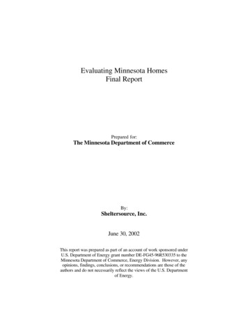
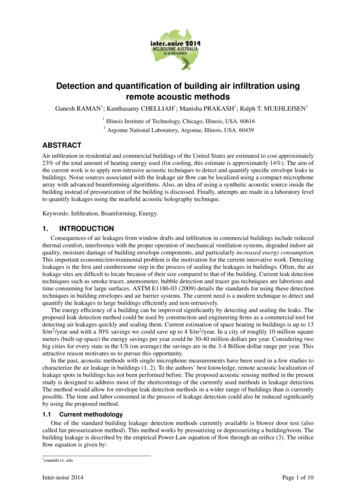
Chapter 1Chapter 1IntroductionIntroduction1.1 What is a Blower Door?The Blower Door is a diagnostic tool designed to measure the airtightness of buildings and to help locate airleakage sites. Building airtightness measurements are used for a variety of purposes including: Documenting the construction airtightness of buildings.Estimating natural infiltration rates in houses.Measuring and documenting the effectiveness of airsealing activities.Measuring duct leakage in forced air distribution systems.The Blower Door consists of a powerful, calibrated fan that is temporarily sealed into an exterior doorway. Thefan blows air into or out of the building to create a slight pressure difference between inside and outside. Thispressure difference forces air through all holes and penetrations in the exterior envelope. By simultaneouslymeasuring the air flow through the fan and its effect on the air pressure in the building, the Blower Door systemmeasures the airtightness of the entire building envelope. The tighter the building (e.g. fewer holes), the less airyou need from the Blower Door fan to create a change in building pressure.Figure 1: Blower Door Depressurization Test2The ENERGYCONSERVATORYDIAGNOSTIC TOOLS TO MEASURE BUILDING PERFORMANCE
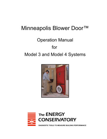
Chapter 1IntroductionA typical Blower Door test will include a series of fan flow measurements at a variety of building pressuresranging from 60 Pascals to 15 Pascals (one Pascal (Pa) equals approximately 0.004 inches of water column).Tests are conducted at these relatively high pressures to mitigate the effects of wind and stack effect pressureson the test results. Sometimes a simple “one-point” test is conducted where the building is tested at a singlepressure (typically 50 Pascals). This is done when a quick assessment of airtightness is needed, and there is noneed to calculate leakage areas (i.e. estimate the cumulative size of the hole in the building envelope).Figure 2: Graph of Blower Door Test DataFlow through theBlower Door fan(BuildingLeakage)Pressure difference between insideand outside (Building Pressure)It takes about 20 minutes to set-up a Blower Door, conduct a test, and document the airtightness of a building.In addition to assessing the overall airtightness level of the building envelope, the Blower Door can be used toestimate the amount of leakage between the conditioned space of the building and attached structuralcomponents such as garages, attics and crawlspaces. It can also be used to estimate the amount of outsideleakage in forced air duct systems. And because the Blower Door forces air through all holes and penetrationsthat are connected to outside, these problem spots are easier to find using chemical smoke, an infrared camera orsimply feeling with your hand. The airtightness measurement can also help you assess the potential forbackdrafting of natural draft combustion appliances by exhaust fans and other mechanical devices, and helpdetermine the need for mechanical ventilation in the house.1.2 Air Leakage BasicsTo properly utilize the diagnostic capabilities of your Blower Door, it is important to understand the basicdynamics of air leakage in buildings. For air leakage (infiltration or exfiltration) to occur, there must be both ahole or crack, and a driving force (pressure difference) to push the air through the hole. The five most commondriving forces which operate in buildings are:3The ENERGYCONSERVATORYDIAGNOSTIC TOOLS TO MEASURE BUILDING PERFORMANCE
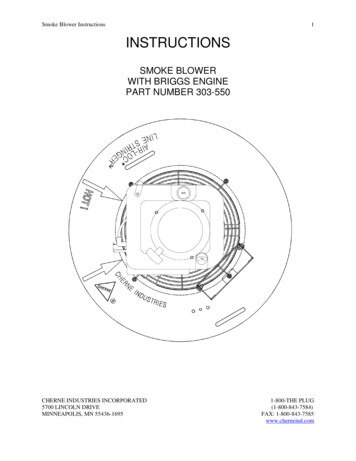
Chapter 1Introduction1.2.a Stack Effect:Stack effect is the tendency for warm buoyant air to rise and leak out the top of the building and be replaced bycolder outside air entering the bottom of the building (note: when outside air is warmer than inside air, thisprocess is reversed). In winter, the stack effect creates a small positive pressure at the top of the building andsmall negative pressures at the bottom of the building. Stack effect pressures are a function of the temperaturedifference between inside and outside, the height of the building, and are strongest in the winter and very weakin the summer. Stack induced air leakage accounts for the largest portion of infiltration in most buildings.1.2.b Wind Pressure:Wind blowing on a building will cause outside air to enter on the windward side of the building, and building airto leak out on the leeward side. At exposed sites in windy climates, wind pressure can be a major driving forcefor air leakage.1.2.c Point Source Exhaust or Supply Devices:Chimneys for combustion appliances and exhaust fans (e.g. kitchen and bath fans) push air out of the buildingwhen they are operating. Air leaving the building from these devices causes a negative pressure in the buildingwhich draws outside air into holes and cracks in the building envelope. Supply fans (e.g. positive pressureventilation fan) deliver air into the building creating a positive pressure which pushes inside air out of thebuilding through holes and cracks in the building envelope. (The interaction of ventilation fans on building airleakage and pressures is discussed in Chapter 10)1.2.d Duct Leakage to the Outside:Leaks in forced air duct systems (to the outside) create pressures which increase air leakage in buildings. Leaksin supply ducts act like exhaust fans causing negative building pressures. Leaks in return ducts act like supplyfans creating positive pressures in buildings. (Duct leakage and duct leakage diagnostics are discussed in moredetail in Chapter 9).1.2.e Door Closure Coupled with Forced Air Duct Systems:Research has shown that in buildings with forced air duct systems, imbalances between supply and return ductscan dramatically increase air leakage. For example, a study conducted in Florida showed that infiltration rates inmany houses were doubled whenever the HVAC system fan was operating due to pressures caused by doorclosure. In the Florida houses, closing of bedroom doors created large duct imbalances by effectively cutting offthe bedroom supply registers from the central return registers located in the main part of the house. (Ductleakage and duct leakage diagnostics are discussed in more detail in Chapter 9)1.3 Common Air Leakage SitesCommon air leakage sites are shown in Figure 3 below. Notice how as warm air rises due to the stack effect, ittends to escape through cracks and holes near the top of the building. This escaping air causes a slight negativepressure at the bottom of the building which pulls in cold air through holes in the lower level. Air sealingactivities should usually begin at the top of the building because this is where the largest positive pressures existand where many of the largest leakage sites (and potential condensation problems) can be found.4The ENERGYCONSERVATORYDIAGNOSTIC TOOLS TO MEASURE BUILDING PERFORMANCE
Chapter 1IntroductionThe next most important location of leaks is in the lowest part of the building. The bottom of the building issubject to the largest negative pressures, which induces cold air infiltration. Importantly, if spillage pronenatural draft combustion appliances are present, do not seal lower level building leaks unless you have firstaddressed leaks in the attic or top part of the building. Sealing only lower level leakage areas while leaving largehigh level leaks could create large enough negative pressures to cause combustion appliance backdrafting.Figure 3: Common Air Leakage SitesIn addition to these common leakage sites, there can also be large leakage paths associated with hiddenconstruction details such as attached porches, cantilevered floors and overhangs. Figures 4 - 6 show a numberof potentially important leakage paths which are often overlooked by crews using traditional weatherizationtechniques. Use of densely blown cellulose insulation or other barrier-type air sealing techniques at these keyjunctures often result in dramatic air leakage reductions.Figure 4: Hidden Construction Details5The ENERGYCONSERVATORYDIAGNOSTIC TOOLS TO MEASURE BUILDING PERFORMANCE
Chapter 1Figure 5: Leak from Attached PorchIntroductionFigure 6: Common Kneewall LeakForced air system ductwork can also be a major air leakage site. Even small leaks in ductwork can result insignificant air leakage due to the high pressures found in ducts whenever the heating or cooling system isoperating. More information on duct leakage can be found in Chapter 9.6The ENERGYCONSERVATORYDIAGNOSTIC TOOLS TO MEASURE BUILDING PERFORMANCE
Chapter 2Chapter 2System ComponentsSystem ComponentsThis Manual includes operating instructions for the following models of Minneapolis Blower Door: Model 3/110V SystemModel 3/230 SystemModel 4/230V System (CE labeled fan and controller)Both the Model 3 and Model 4 Minneapolis Blower Doorsystems are comprised of three separate components:1.2.3.Blower Door FanAccessory Case with Test Instrumentation (buildingpressure and fan flow gauges), Fan Speed Controller andNylon Door PanelThe Adjustable Aluminum Door FrameWhile the Blower Door fan motor, flow sensor and speed controller vary slightly between the three differentMinneapolis Blower Door systems, the other system components are identical.PC based test analysis software (TECTITE ) is also available to help you document and analyze Blower Doortest results.2.1 Blower Door FanThe Blower Door fan consists of a molded fan housing with a 3/4 h.p. permanent split capacitor AC motor. Airflow through the fan is determined by measuring the pressure at the flow sensor which is attached to the end ofthe motor. When the fan is operating, air is pulled into the inlet side of the fan and exits through the exhaust side(a metal fan guard is bolted to the exhaust side of the fan).The Blower Door fan can accurately measure airflow over a wide range of flow rates using a series of calibratedFlow Rings which are attached to the inlet of the fan. The standard Minneapolis Blower Door system comeswith 2 Flow Rings (A and B) capable of measuring flows as low as 300 Cubic Feet per Minute (cfm). OptionalRings C, D and E are available which allows flow measurements as low as 85, 30 and 11 cfm respectively.Model 3 Fan with Rings A and B7The ENERGYCONSERVATORYDIAGNOSTIC TOOLS TO MEASURE BUILDING PERFORMANCE
Chapter 2System ComponentsThe main distinguishing feature between the Model 3 and Model 4 fans is the shape of the flow sensor attachedto the fan motor. Model 3 fans (both 110V and 230V) use a round white plastic flow sensor, while the Model 4fan uses a flow sensor manufactured out of stainless steel tubing.Model 3 Fan and Flow SensorModel 4 Fan and Flow Sensor2.1.a Determining Fan Flow and Using the Flow Rings:Fan pressure readings from the flow sensor are easily converted to fan flow readings by using a FlowConversion Table (see Appendix B), by reading flow directly from the Blower Door gauge(s), or through theuse of the TECTITE Blower Door Test Analysis Software. The Blower Door fan has 6 different flow capacityranges depending on the configuration of Flow Rings on the fan inlet. Table 1 below show the approximate flowrange of the Blower Door fan under each of the 6 inlet configuration. The greatest accuracy in fan flow readingswill always be achieved by installing the Flow Ring with the smallest opening area, while still providing thenecessary fan flow. Importantly, when taking Blower Door measurements, stand at least 12 inches from the sideof the fan inlet. Standing directly in front of the fan may affect the flow readings and result in erroneousmeasurements.Table 1: Fan Flow RangesFan ConfigurationOpen (no Flow Ring)Ring ARing BRing CRing DRing EFlow Range (cfm) forModel 3 Fan6,100 - 2,4352,800 - 9151,100 - 300330 85115 3045 11Flow Range (cfm) forModel 4 Fan4,850 - 2,0902,500 - 790900 - 215260 45125 3050 11To install Flow Ring A, place Ring A onto the inlet side of the fanhousing and rotate the 8 fastener clips attached to the housing flange sothat they rotate over the edge of Ring A and secure it in place.8The ENERGYCONSERVATORYDIAGNOSTIC TOOLS TO MEASURE BUILDING PERFORMANCE
Chapter 2System ComponentsTo Install Flow Ring B, place Ring B in the center of Ring A androtate the 6 fastener clips attached to Ring A so that they rotate overthe edge of Ring B and secure it in place.In addition to Flow Rings A and B, the standard Minneapolis BlowerDoor comes with a solid circular No-Flow Plate to seal off the fanopening. The No-Flow Plate is attached to Ring B in the samemanner that Ring B attaches to Ring A.The No-Flow Plate and Rings A and B can be removed separately, orall 3 pieces can be removed at the same time by releasing the 8fastener clips holding Ring A to the fan housing.Installation and use of optional Flow Rings C, D and E are discussedin Appendix C.2.2 Test Instrumentation (Pressure and Fan Flow Gauges)This manual covers three instrumentation options typically used with the Minneapolis Blower Door; the DG700 Digital Gauge, the DG-3 Digital Gauge, and the APT System.2.2.a DG-700 and DG-3 Digital Pressure Gauges:The DG-700 and DG-3 are differential pressure gauges which measure the pressure difference between either oftheir Input pressure taps and its corresponding bottom Reference pressure tap. Both gauges have two separatemeasurement channels which allows you to monitor the building pressure and fan pressure (air flow) signalsduring the Blower Door test (the DG-700 allows for simultaneous display of both channels, while the DG-3 candisplay one channel at a time). In addition, both gauges are able to directly display air flow through the BlowerDoor fan (the DG-700 can display fan flow in units of cfm, l/s and m3/hr). The digital gauge is shipped in aseparate padded case which is stored in the Blower Door accessory case. Also included is a black mountingboard to which the digital gauge can be attached using the Velcro strips found on the back of the gauge.The DG-700 can also be used to automate control of the Blower Door fan using the following two features: The-DG-700 can be used along with TECTITE software and a user supplied laptop computer to conduct afully automated Blower Door test. When conducting automated tests, the speed of the Blower Door fan iscomputer controlled while the TECTITE program simultaneously monitors the building pressure and fanflow using the DG-700’s two pressure channels. Test results are recorded, displayed on the screen, and canbe saved to a file. Note: Automated testing requires the TECTITE software and special cabling. Newer DG-700 gauges have a built-in “Cruise Control” feature which allow the user to control the BlowerDoor fan to maintain a constant building pressure, without using the TECTITE software or a laptopcomputer.9The ENERGYCONSERVATORYDIAGNOSTIC TOOLS TO MEASURE BUILDING PERFORMANCE
Chapter 2DG-700 Pressure GaugeSystem ComponentsDG-3 Pressure Gauge2.2.b Automated Performance Testing System :The Automated Performance Testing (APT) system performs fully automated BlowerDoor tests from a user supplied laptop or desktop computer using TEC’s TECTITEsoftware. The TECTITE software allows the user to select among various airtightnesstesting procedures, including a cruise control option which maintains the building at anyuser-defined pressure. The APT system automatically adjusts the speed of the BlowerDoor fan while simultaneously monitoring the building pressure and fan flow using 2on-board differential pressure channels. Test results are recorded, displayed on thescreen, and can be saved to a file.If the APT system contains more than 2 installed pressure channels, the additionalchannels can be used to monitor and record pressures in attached zones (e.g. attic orcrawlspace) during the automated Blower Door test.The APT system consists of the following components: One Data Acquisition Box (DAB) with 2 to 8 on-board pressure channels andphone jacks for 8 voltage input channels.One 6’ serial cable (w/ 9 pin connectors) to connect the DAB with your computer.One 12V power supply for the DAB.One CD containing the TECTITE software.The Data Acquisition Box (DAB) comes fastened to a black plastic mounting board. The mounting board mayalso contain two electrical outlets which can be used to power the Blower Door fan, DAB or a lap-top computer.Note: When us
Minneapolis Blower Door Operation Manual for Model 3 and Model 4 Systems The Energy Conservatory 2801 21st Ave. S., Suite 160 Minneapolis, MN 55407 (612) 827-1117 (Ph) (612) 827-1051 (Fax) www.energyconservatory.com email: info@energyconservatory.com Minneapolis Blower Door, TECTITE, Duct Mask and Automated Performance Testing (APT) System are