Transcription
MODEL 3 MINNEAPOLIS BLOWER DOOR SYSTEMUSER MANUAL
ENERGY CONSERVATORY WARRANTYEXPRESS LIMITED WARRANTYSeller warrants that this product, under normal use and service as described in the operator’s manual, shall befree from defects in workmanship and material for a period of 24 months, or such shorter length of time as may bespecified in the operator’s manual, from the date of shipment to the Customer.LIMITATION OF WARRANTY AND LIABILITYThis limited warranty set forth above is subject to the following exclusions: With respect to any repair services rendered, Seller warrants that the parts repaired or replaced will be freefrom defects in workmanship and material, under normal use, for a period of 90 days from the date of shipmentto the Purchaser.Seller does not provide any warranty on finished goods manufactured by others. Only the originalmanufacturer’s warranty applies.Unless specifically authorized in a separate writing, Seller makes no warranty with respect to, and shall haveno liability in connection with, any goods which are incorporated into other products or equipment by thePurchaser.All products returned under warranty shall be at the Purchaser’s risk of loss. The Purchaser is responsiblefor all shipping charges to return the product to The Energy Conservatory. The Energy Conservatory will beresponsible for return standard ground shipping charges. The Customer may request and pay for the addedcost of expedited return shipping.The foregoing warranty is in lieu of all other warranties and is subject to the conditions and limitations statedherein. No other express or implied warranty IS PROVIDED, AND THE SELLER DISCLAIMS ANY IMPLIEDWARRANTY OF FITNESS for particular purpose or merchantability.The exclusive remedy of the purchaser FOR ANY BREACH OF WARRANTY shall be the return of the product to thefactory or designated location for repair or replacement, or, at the option of The Energy Conservatory, refund of thepurchase price.The Energy Conservatory’s maximum liability for any and all losses, injuries or damages (regardless of whethersuch claims are based on contract, negligence, strict liability or other tort) shall be the purchase price paid for theproducts. In no event shall the Seller be liable for any special, incidental or consequential damages. The EnergyConservatory shall not be responsible for installation, dismantling, reassembly or reinstallation costs or charges.No action, regardless of form, may be brought against the Seller more than one year after the cause of action hasaccrued.The Customer is deemed to have accepted the terms of this Limitation of Warranty and Liability, which containsthe complete and exclusive limited warranty of the Seller. This Limitation of Warranty and Liability may notbe amended or modified, nor may any of its terms be waived except by a writing signed by an authorizedrepresentative of the Seller.TO ARRANGE A REPAIRPlease call The Energy Conservatory at 612-827-1117 before sending any product back for repair or to inquire aboutwarranty coverage. All products returned for repair should include a return shipping address, name and phonenumber of a contact person concerning this repair, and the purchase date of the equipment.
SAFETY INFORMATION The blower door fan should only be connected to a properly installed and tested power supply. In case ofemergencies, disconnect the power cord from the AC power mains outlet. During installation, use the nearest readilyaccessible power outlet and keep all objects away from interfering with access to the outlet. Disconnect the power plug from the blower door fan receptacle before examining or making any adjustments to thefan motor, blades or electrical components. The blower door fan is a very powerful and potentially dangerous piece of equipment if not used and maintainedproperly. Carefully examine the fan before each use. If the fan housing, fan guards, blade, controller or cordsbecome damaged, do not operate the fan until repairs have been made. Repairs should only be made by The EnergyConservatory. If you notice any unusual noises or vibrations, stop and unplug the fan. If you can’t find the source of the problem,contact the manufacturer/distributor. Keep people, animals and objects away from the blower door fan when it is operating. Press the power plug firmly into the power receptacle on the blower door fan, and the AC power mains outlet. Failureto do so can cause overheating of the power cord and possible damage. Do not use ungrounded outlets or adapter plugs. Never remove or modify the grounding prong. Use only approvedand inspected electrical wiring and connections. Do not operate the blower door fan if the motor, controller or any of the electrical connections are wet. For long-term operation, such as maintaining building pressure while air-sealing, use a flow ring whenever possibleto ensure proper cooling of the blower door fan motor. This will minimize the heating of the fan and is important inwarmer weather. Do not reverse the blower door fan (if the fan has a flow direction switch) while the blades are turning. The motor is thermally protected and if you experience a motor shut down, be sure to turn off the fan speed controllerso that the fan does not restart unexpectedly after the motor cools down. The operator should wear hearing protection when in close proximity to the fan operating at high speed. Adjust all combustion appliances so they do not turn on during the test. If combustion appliances turn on during adepressurization test, it is possible for flames to be sucked out of the combustion air inlet (flame roll-out). This is afire hazard and can possibly result in high CO levels. If there are attached spaces (e.g. townhouses) that could contain a vented combustion appliance, either adjust thoseappliances to prevent them from turning on during the test, or be sure that the attached spaces are not depressurizedor pressurized when the blower door is operating. Be sure that fires in fireplaces and wood stoves are completely out before conducting a test. Take precautions toprevent ashes from being sucked into the building during the test. In most cases it will be necessary to either tapedoors shut, clean out the ashes, and/or cover the ashes with newspaper. Be sure you have returned the building to its original condition before leaving. This includes turning the thermostatand water heater temperature controls to their original setting. Always check to see that furnace, water heater andgas fireplace pilot lights have not been blown out during the blower door test - re-light them if necessary. Removeany temporary seals from fireplaces or other openings sealed during the test. If combustion safety problems are found, tenants and building owners should be notified immediately and stepstaken to correct the problem including notifying a professional heating contractor if basic remedial actions are notavailable. Remember, the presence of elevated levels of carbon monoxide in ambient building air or in combustionproducts is a potentially life threatening situation. Air sealing work should not be undertaken until existingcombustion safety problems are resolved, or unless air sealing is itself being used as a remedial action.
TABLE OF CONTENTSCHAPTER 11Blower Door System Details Blower Door Fan, Speed Controller and Flow Rings Digital Gauge OptionsCHAPTER 24Aluminum Frame and Door Panel Where to Install the Blower Door Frame How to Assemble and Install the Blower Door Frame and Panel Installing the Blower Door Fan Attaching the Gauge Mounting BoardCHAPTER 37Setting Up the Building for the TestAfter the TestFinding Air LeaksCHAPTER 49Using the Can’t Reach 50 FactorTesting in Windy WeatherBlower Door Fan Calibration Flow Conversion Tables: Flow CFM Flow Conversion Tables: Rings D and E Air Density Correction Factors: Depressurization and PressurizationBlower Door System MaintenanceSpecificationsOTHER RESOURCES21Software InformationInstructional VideosAdditional Guides
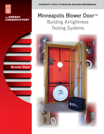
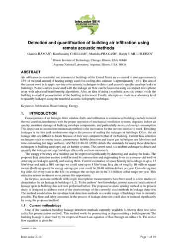
CHAPTER 1Blower Door System DetailsThe blower door fan consists of a molded fan housing with a 3/4 horsepowerpermanent split capacitor AC motor. Air flow through the fan is determined bymeasuring the pressure at the flow sensor which is attached to the end of the motor.When the fan is operating, air is pulled into the inlet side of the fan and exits throughthe exhaust side (a metal fan guard is bolted to the exhaust side of the fan).The blower door fan can accurately measure airflow over a wide range of flow ratesusing a series of calibrated flow rings which are attached to the inlet of the fan. Thestandard Minneapolis Blower Door System comes with two flow rings (A and B), andoptional flow rings are C, D and E.Fan Flow RangesRingOpen (no flow ring)Ring ARing BRing C (optional)Ring D (optional)Ring E (optional)Flow Range in CFM6,100 - 2,4352,800 - 9151,100 - 300330 - 85115 - 3045 - 11The table above shows the approximate flow range of the blower door fan whenused with each flow ring. The greatest accuracy in fan flow readings will alwaysbe achieved by installing the flow ring with the smallest opening area, while stillproviding the necessary fan flow. When taking blower door measurements, standat least 12 inches away from the fan. Standing directly in front of the fan mayaffect the flow readings and result in erroneous measurements. To install flow ring A, place ring A onto the inlet side of the fan housing and rotate the eight fastener clips attached tothe fan housing so that they rotate over the edge of ring A and secure it in place.To Install flow ring B, place ring B in the center of ring A and rotate the six fastener clipsattached to ring A so that they rotate over the edge of ring B and secure it in place.In addition to flow rings A and B, the blower door comes with a solid circular no flowplate to seal off the fan opening. The no flow plate is attached to ring B in the samemanner that ring B attaches to ring A.The no flow plate and rings A and B can be removed separately, or all three pieces canbe removed at the same time by releasing the eight fastener clips holding ring A to thefan housing.Installation and use of flow rings C, D and E are discussed on our website.1
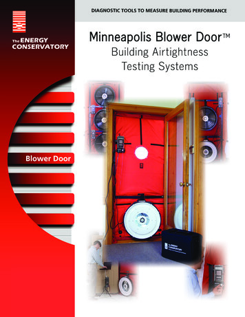
CHAPTER 1Fan Speed ControllerFan speed is adjusted using the adjustment knob on the face of thespeed controller. Model 3 blower door systems come with the fan speedcontroller clipped onto the black mounting board supplied with the system.The Model 3 controller can be removed from the mounting board by slidingthe controller clip off the board.Digital Gauge OptionsDG-1000 Pressure and Flow GaugeThe DG-1000 and DG-700 are differential pressure gauges which measurethe pressure difference between either of their input pressure taps and itsDG-700 Pressure and Flow Gaugecorresponding reference pressure tap. Both gauges have two separatemeasurement channels which allows you to monitor the building pressure and fan pressure (air flow) signals during the blowerdoor test. In addition, both gauges are able to directly display air flow through the blower door fan. The digital gauge is shippedin a separate padded case which is stored in the blower door accessory case. Also included is a black mounting board to whichthe digital gauge can be attached using either the Velcro strips (DG-700 board) or the magnets (DG-1000 board).DG-1000 gauge boardDG-700 gauge board2
CHAPTER 1Both gauges can also be used to automate control of the blower door fan using the following two features: Both gauges have a built-in “cruise control” feature which allow the user to control the blower door fan to maintain aconstant building pressure, without using the TECTITE software or a computer. The gauge can be used along with TECTITE software and a computer to conduct a fully automated blower doortest. When conducting automated tests, the speed of the blower door fan is computer controlled while the TECTITEprogram simultaneously monitors the building pressure and fan flow using the gauge’s two pressure channels. Testresults are recorded, displayed on the screen, and can be saved to a file.3
CHAPTER 2Aluminum Frame and Door PanelThe adjustable aluminum door frame and nylon panel is used to seal the fan into an exterior doorway. The door frame isadjustable to fit a typical size residential door opening. The aluminum frame comes in a soft carrying case and includes: Two 96” vertical pieces Two 45” horizontal pieces One 45” crossbar with Velcro strap One gauge hanger barWhere to Install the Blower Door Frame It is always best to install the blower door system in an exterior doorway of a large open room. Try to avoid installing the fan in a doorway where there are stairways or major obstructions to air flow very close (one tofive feet) to the fan inlet. If the doorway leads to a porch or garage, make sure this space is open to the outside by opening doors and/or windows. The door frame is almost always installed from the inside of the building and may be installed in place of the prime door,the storm door or anywhere in between. Always open the inside door and outside storm door as much as possible during the test to prevent restrictions to airflow.How to Assemble the Blower Door Frame and Nylon Panel Remove all frame pieces from the bag and lay them out on the floor»» Lay the two vertical frame pieces on the floor parallel with each other, cam leverside up.»» Lay one horizontal piece on the floor between the bottom of the two vertical pieces,cam lever side up.»» Lay the second horizontal piece on the floor between the top of the two verticalpieces, cam lever side up.»» Set aside the crossbar with the Velcro strap for later use. Put all cam levers into the relaxed position (lever should be pointing inward, and not bein the horizontal locked position)Relaxed/unlockedLocked Both vertical frame pieces have a silver bar on each end, with a small silverbutton on the bar. Push in the silver button and slide into the end of thehorizontal piece. Note: Two of the buttons will be on the side of the frame facingthe floor.4
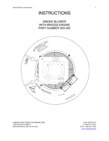
CHAPTER 2 Temporarily install the frame in the doorway»» Stand the frame up and put into the doorway.»» Loosen the knobs on each cam lever.»» Place one foot on the bottom of the frame to hold it place, and extend the top of the frame to the top of the doorway,leaving about a fingers width of space between the top of the frame and the top of the doorway.»» Tighten the knobs on the vertical pieces.»» Extend the frame horizontally so both vertical pieces fit into the doorway, leaving about a fingers width of spacebetween the vertical pieces and the sides of the doorway.»» Tighten the knobs on the horizontal pieces. Attach the nylon panel to the frame and install into doorway»»»»»»Lay the fabric panel on the floor, with the Velcrostraps and blower door logo facing up.»» Remove the frame from the doorway, being sure theknobs on the cam levers are still tightened so theframe doesn’t adjust in size.»» Lay the frame onto the fabric door panel, lining up thetop and bottom horizontal pieces with their respectiveVelcro straps.»» Drape each side of the panel over the frame snuglyand tighten the Velcro straps.»» Stand the frame up near the doorway and run thegreen tubing outside so the end is well awayfrom the nylon panel. Extend the other end throughone of the patches at the bottom corners of the nylonpanel. Pull just enough of it to the inside so it canmake the connection to the gauge.Readjust the frame so it fits snuggly in the door opening and tighten all four adjustment knobs. Now engage all fourcam levers so the frame is secured tightly in the opening.Install the crossbar with the Velcro strap in the lowest slot above the fan hole and tighten the knob so it fits snug.Engage the cam lever. Insert the blower door fan into the hole in the fabric panel»» Set the fan down in front of the panel. For a depressurization test, the side of the fanwith the guard should be facing outside. The side of the fan with the flow rings shouldbe facing inside. (For a pressurization test, insert the fan the other way, with the guardinside the house and the flow rings outside the house.)»» Insert the fan bottom first into the hole, and then work the elastic around the fan untilit’s completely inserted.»» The top of the hole should rest in the middle of the electrical box on top of the fan so theplug inlet and handle are not covered.»» The bottom of the fan should be resting on the lower horizontal frame piece.»» Slip the velcro strap through the fan handle and loop it up and back around the cross bar.5
CHAPTER 2 Attach the gauge mounting board»» The mounting board for the gauge can be attached to any door by using the C-clamp connected to the back of the board.»» The mounting board can also be easily attached to a horizontal surface (book shelf or desk top) by rotating the clamp90 degrees before securing the board.»» The mounting board can be attached to the gauge hanger bar. Connect the gauge hangerbar to either side of the vertical pieces by inserting the hook into one of the remaining slots.Tighten the mounting board clamp onto the hanger bar. Attach the fan speed controller to the bottom of the gauge mounting board by sliding it on usingthe metal clamp on the back of the controller.Insert the female plug from the fan speed controller into the receptacle located on the fanelectrical box. Make sure the plug is inserted completed as the plug or receptacle can overheat ifit’s not.Plug the power cord into an AC outlet that is compatible with the voltage of the fan motor and speed controller. Be surethe controller knob on the fan speed controller is turned all the way counter clockwise to the off position before pluggingin the power cord. Complete setup without gaugeComplete setup with gaugeSee one of the following guides for gauge setup and testing instructionsUsing the DG-1000 with the Minneapolis Blower DoorUsing the DG-700 with the Minneapolis Blower Door6
CHAPTER 3Setting Up the Building for the TestThe following preparations are appropriate when using the blower door to determine retrofit airsealing potential,weatherization effectiveness or estimating natural infiltration rates. If the purpose of the blower door test is to documentconstruction airtightness quality for new houses, additional preparation may be needed. Your program guidelines mayrequire you to prepare the building differently than described below.The building set-up and test procedures below are recommended specifically by The Energy Conservatory. Theseprocedures generally conform to the Canadian General Standards Board (CGSB) standard CGSB-149.10-M86“Determination of the Airtightness of Building Envelopes by the Fan Depressurization Method,” and American Societyfor Testing and Materials (ASTM) standard E779-10 “Standard Test Method for Determining the Air Leakage Rate by FanPressurization.” However, our procedures include options and recommendations that are not contained within the CGSBand ASTM standards. If you need to perform a blower door airtightness test that exactly meets the CGSB, ASTM or someother test procedure (e.g. RESNET), you should obtain a copy of the applicable standard and follow the specific set-updirections contained in the standard.Adjustable Openings Close all storm and prime windows. Close all exterior doors and interior attic or crawlspace hatches which are connected to conditioned spaces. Alsoclose exterior crawl space hatches and vents if they are normally closed most of the year. Open all interior doors to rooms that are conditioned. The object here is to treat the entire building as one conditionedspace and to subject all of the leaks in the building to the same pressure difference. Because few house basementscan be completely sealed from the house and usually some conditioning of the basement is desirable, they aretypically included as conditioned space. Tape plastic over window air conditioners if they appear to be a source of air leakage into the building and they aretypically removed during a large part of the year.Combustion Appliance/Exhaust Devices Adjust all combustion appliances so they do not turn on during the test. This is commonly done by temporarily turningoff power to the appliance, or setting the appliance to the “Pilot” setting. If combustion appliances turn on during adepressurization test, it is possible for flames to be sucked out of the combustion air inlet (flame rollout). This is afire hazard and can possibly result in high CO levels. If there are attached spaces (e.g. townhouses) that could contain a vented combustion appliance, either adjust thoseappliances to prevent them from turning on during the test, or be sure that the attached spaces are not depressurizedor pressurized when the Blower door is operating. Be sure that fires in fireplaces and woodstoves are completely out. Take precautions to prevent ashes from beingsucked into the building during the test. In most cases it will be necessary to either tape doors shut, clean out theashes, and/or cover the ashes with newspaper. Turn off all exhaust fans, vented dryers, air conditioners, ventilation system fans and air handler fans.After the TestBe sure you have returned the building to its original condition before leaving. This includes turning the thermostatand water heater temperature controls to their original setting. Always check to see that furnace, water heater andgas fireplace pilot lights have not been blown out during the blower door test (re-light them if necessary). Remove anytemporary seals from fireplaces, woodstoves or other openings sealed during the test. In addition, combustion safetytests should usually be performed before leaving the house.7
CHAPTER 3Finding Air LeaksThere are many techniques that are used to find air leaks with the blower door. Air leaks between the interior and exterior ofthe building often follow long and complicated leakage paths. Typically, the air sealing goal is to find where the leaks crossthe exterior envelope of the building and to concentrate sealing activities on those areas. Using Your HandThe easiest method and one that is used most often is to depressurize the building and walk around the inside, checkingfor leaks with your hand. When you are looking for leaks, let the blower door fan run at a speed which generatesbetween 20 and 30 Pascals of building pressure. You should get in the habit of always using the same pressure soyou will get a good feel for what is a big leak and what is not. An entire room can be checked quickly if there is a doorbetween it and the rest of the house. Standing just outside of the room, close the door most of the way, leaving about aone inch crack. A large blast of air coming through this crack indicates large leaks between that room and the outdoors. Using a Chemical Smoke PufferIn houses, many of the most important leaks are found between the house and the attic or between the house and aventilated crawlspace. These leaks usually will not be easy to find unless you physically go into the attic or crawlspace.The use of a handheld smoke puffer is often helpful in these areas. With the house depressurized (and the crawlspaceor attic access door shut), you can squirt small puffs of smoke toward suspected leakage sites from the attic orcrawlspace and watch to see if the smoke gets sucked into the leak. With a piece of tubing attached to the smokepuffer, you can often reach deep into corners or in hard to reach spots. A smoke puffer or a pressure pan is a necessitywhen looking for leaks in the forced air ductwork. Using an Infrared CameraThe ideal technique for finding leaks is to use an infrared scanner with a blower door. This procedure usually involvesperforming two infrared scans from the interior of the building; one before turning on the blower door and one afterthe blower door has been depressurizing the building for five to 10 minutes. As long as the air being sucked in throughthe leaks is either warmer or colder than the interior of the house, the area surrounding the leakage path will changetemperature and show up on the infrared scanner screen. Even if there is little temperature difference between insideand outside, an infrared scan may still be possible if the attic space has been warmed from solar radiation on the roof orthe crawlspace has been cooled from the ground. A temperature difference of about five to 10 degrees is sufficient toexpose the important leaks. This technique often allows you to find significant leaks without having to enter the attic orcrawlspace. Other Diagnostic TechniquesMany important air leaks in a building are not direct leaks to the outside. Air leaks often follow complicated pathsthrough building cavities and through unconditioned zones (such as attics, crawlspaces or garages) on their way into orout of the building. Attic bypasses, found in many houses, are a good example of a series leak. Air leaving the house firstmust flow through the ceiling/attic boundary and then through the attic/roof boundary before exiting the house.Diagnostic procedures have been developed to analyze series leakage. These procedures, called zone pressurediagnostics (ZPD), are widely used by weatherization professionals to prioritize airsealing efforts in houses byestimating the amount of air leakage from attached zones (e.g. attics, crawlspaces, garages and basements). ZPDtechniques typically combine blower door airtightness test results with zone pressure measurements made both beforeand after an opening or hole has been added to one surface of the zone being tested.Duct leakage to the outside can add to your overall airleakage values during a blower door test. One method of findingthose leaks is using a pressure pan. You may also quantify the leakage to the outside by using theblower door subtraction method.8
CHAPTER 4Using the Can’t Reach 50 Factor: One-Point TestIf you were performing a one-point test and the blower door fan was unable to depressurize the building by approximately50 Pascals because one of the flow rings was installed, remove the ring and repeat the test (removing the flow ring willincrease the maximum air flow available from the fan). If you were not able to depressurize the building by approximately50 Pascals (with the “open fan” running at full speed) because the building is extremely leaky, use the followinginstructions:For DG-1000 and DG-700 UsersNo adjustments to the test procedure above are necessary other than to make sure the gauge was in the PR/ FL @50mode during the one-point test. If you can not achieve the target test pressure of 50 Pascals because the building isextremely leaky, a CFM50 leakage estimate will automatically be displayed on Channel B. The leakage estimate shown onChannel B is determined by continuously adjusting the measured air flow from the blower door fan to a test pressure of50 Pascals, using the real-time Channel A building pressure reading and the can’t reach 50 factors shown below.Building Pressure (Pa)CRF 94162.10142.29122.53102.85Example: With the fan running full speed, you are able toachieve a building pressure of 28 Pascals with a measured fanflow of 5,600 cfm. The corresponding CRF Factor for a buildingpressure of 28 Pascals is 1.46. The estimated flow needed toachieve the target pressure of 50 Pascals is5,600 x 1.46 8,176 cfm.50Can’t Reach FiftyFactor9 Current Test Pressure (Pa)(Channel A)0.65
CHAPTER 4Potential Errors In one-point CFM50 Estimate from Using the CRF FactorsThe table below show the potential errors in the one-point CFM50 leakage estimates from using the CRF factors. Thereare two main sources of error: The actual test pressure (Channel A) not being equal to the target pressure of 50 Pascals. The actual exponent of the leaks being measured differing from the assumed exponent of 0.65.Actual Exponent “n”Test Pressurein Pa(Channel -1.3%0.0%1.3%2.6%For example, the table shows that for a one-point 50 Pa blower door building airtightness test, a 2.5% error wouldbe introduced if the leakage estimate was determined at an actual test pressure of 30 Pa (Channel A), and the actualexponent of the leaks was 0.60 rather than the assumed value of 0.65.Testing in Windy WeatherDuring strong or gusty winds, building pressure readings can vary significantly. As wind gusts contact a building, theactual pressures within the building will change (10 to 20 Pa changes are common in windy weather). Under theseconditions, you will need to spend more time watching the gauges to determine the “best” reading. Use of the timeaveraging functions can help stabilize readings in windy conditions.While conducting a multi-point blower door test over a wide range of building pressures will tend to even out some ofthe error introduced from moderate wind fluctuations, significant wind related error can still exist. Under very windyconditions, it is sometimes impossible to manually collect accurate and repeatable test data. Under these conditions,conducting a fully automated test using a DG-1000, and software or apps, may be the only way to collect accurate andrepeatable test results. During an automated test hundreds of simultaneous measurements of building pressure and fanflow are quickly collected greatly reducing the variability of tests results due to wind.10
CHAPTER 4Blower Door Fan CalibrationModel 3 (110V) Calibration ParametersFan ConfigurationCalibration ParametersOpen FanFlow (CFM) 506.8 x (Fan pressure in Pasc
The blower door fan can accurately measure airflow over a wide range of flow rates using a series of calibrated flow rings which are attached to the inlet of the fan. The standard Minneapolis Blower Door System comes with two flow rings (A and B), and optional flow rin