Transcription
ARINC 600RACK AND PANEL CONNECTORSMILITARY & AEROSPACECANADA
ARINC 600TABLE OF CONTENTSIntroduction . . . . . . . . . . . . . . . . . . . . . . . . . . . . . . . . . . . . . . . . . . . . . . . . . . . . . . . . . . . .2Performance & Material Specification . . . . . . . . . . . . . . . . . . . . . . . . . . . . . . . . . . . . . . . .3Next Generation ARINC 600:Introduction . . . . . . . . . . . . . . . . . . . . . . . . . . . . . . . . . . . . . . . . . . . . . . . . . . . . . . . . . . . .4Technical Information . . . . . . . . . . . . . . . . . . . . . . . . . . . . . . . . . . . . . . . . . . . . . . . . . . . .5How-to-order . . . . . . . . . . . . . . . . . . . . . . . . . . . . . . . . . . . . . . . . . . . . . . . . . . . . . . . . . .6Drawing Shell Size 3 . . . . . . . . . . . . . . . . . . . . . . . . . . . . . . . . . . . . . . . . . . . . . . . . . . . . .7ARINC 600:How-to-order . . . . . . . . . . . . . . . . . . . . . . . . . . . . . . . . . . . . . . . . . . . . . . . . . . . . . . . . . . .8Dimensional Drawings, Size 1, Plug & Receptacle. . . . . . . . . . . . . . . . . . . . . . . . . . . . . . .9Dimensional Drawings, Size 2, Plug & Receptacle. . . . . . . . . . . . . . . . . . . . . . . . . . . . . . .10Dimensional Drawings, Size 3, Plug & Receptacle. . . . . . . . . . . . . . . . . . . . . . . . . . . . . . .11Insert Arrangements Size 1 (A/B) (C) . . . . . . . . . . . . . . . . . . . . . . . . . . . . . . . . . . . . . . . . .12Insert Arrangements Size 2 & 3 (A/B) . . . . . . . . . . . . . . . . . . . . . . . . . . . . . . . . . . . . . . . . .13Insert Arrangements Size 2 & 3 (C). . . . . . . . . . . . . . . . . . . . . . . . . . . . . . . . . . . . . . . . . . .14Insert Layout Designator Size 1 . . . . . . . . . . . . . . . . . . . . . . . . . . . . . . . . . . . . . . . . . . . . .15Insert Layout Designator Size 2 . . . . . . . . . . . . . . . . . . . . . . . . . . . . . . . . . . . . . . . . . . . . .16-18Insert Layout Designator Size 3 . . . . . . . . . . . . . . . . . . . . . . . . . . . . . . . . . . . . . . . . . . . . .19-21Mounting Modifiers . . . . . . . . . . . . . . . . . . . . . . . . . . . . . . . . . . . . . . . . . . . . . . . . . . . . . .22-24Polarizing Positions . . . . . . . . . . . . . . . . . . . . . . . . . . . . . . . . . . . . . . . . . . . . . . . . . . . . . .25-27Panel Cutout . . . . . . . . . . . . . . . . . . . . . . . . . . . . . . . . . . . . . . . . . . . . . . . . . . . . . . . . . . .28Contacts:Contact Data, Crimp, PC Tails . . . . . . . . . . . . . . . . . . . . . . . . . . . . . . . . . . . . . . . . . . . . .29Contact Data, Protective Covers, Transceivers . . . . . . . . . . . . . . . . . . . . . . . . . . . . . . . . .30Contacts Crimp Pin & Sockets. . . . . . . . . . . . . . . . . . . . . . . . . . . . . . . . . . . . . . . . . . . . . .31How-to-order Backshells . . . . . . . . . . . . . . . . . . . . . . . . . . . . . . . . . . . . . . . . . . . . . . . . .32Contact Amphenol Canada for more information at 416-291-4401 www.amphenolcanada.com1
Introduction to Rack and Panel ConnectorsARINC600INTRODUCTION2ARINC 600 Connectors are a recognized standard rack and panel connector forAircraft applications. The ARINC 600 is the successor to the ARINC 404 for many ofthe new avionic designs. Compared to the ARINC 404, the ARINC 600 features lowermating force contacts, increased contact count and a front release, floating keyingsystem.Amphenol’s extensive product offering will meet the most demanding needs of ourcustomers. At the design-in stage, Amphenol’s sales engineers will work with you toselect a connector from our standard product line or coordinate the design of anapplication specific connector. Amphenol’s ARINC 600 rack and panel connectorsare designed to meet all relevant ARINC 600 connector specifications.Amphenol ARINC 600 Connectors offer: Low insertion force contactsBoth environmental and non-environmental versionsFront removable keying postsField replaceable inserts for size 22 and power contactsUp to 800 size 22 contact positions in one connectorCrimp, coaxial, power, printed circuit, and wire wrap contactsWaveguide connectionsContact Amphenol Canada for more information at 416-291-4401 www.amphenolcanada.comDownload 2D drawings & 3D models using our online configurator.
Performance and Material SpecificationsCANADAAmphenol “A” Series Connectors are designed per ARINC 600 specifications and utilizepin and socket contacts manufactured in conformance with MIL-C-39029B.PERFORMANCE SPECIFICATIONS1500 Vrms500 Vrms @ 50,000 ft. (15,240m)Contact continuous currentratings:Size 22 - 5.0A: Size 20 - 7.5ASize 16 - 13.0A; Size 12 - 23.0A600Dielectric withstandingvoltage (DWV):Contact resistance:8.0 milliohms, initial (max.)11.0 milliohms, conditioned (max.)Size 20:7.0 milliohms, initial (max.)8.5 milliohms,conditioned (max.)Size 16:3.5 milliohms, initial (max.)5.0 milliohms, conditioned (max.)Size 12:2.0 milliohms, initial (max.)2.5 milliohms, conditioned (max.)Insulation resistance:5.0 gigaohms min. at 500 VDCEngagement/separationforce:Shell size 1 - 27 Ibs. (120N) max.Shell size 2 - 60 Ibs. (267N) max.Shell size 3 - 105 Ibs. (467N) max.Durability:500 cycles min. - mating & unmatingTemperature range:65 C (-86 F) to 125 C ( 275 F)Fluid immersion (Class Aonly) resistance:(1) Hydraulic fluid per MIL-H-5606(2) Lubricating oil (synthetic) per MIL-L-23699(3) 1:3 mix of isopropyl alcohol& mineral spirits per FED. SPECS.TT-I-735 &TT-T-291 respectivelyVibration:MIL-STD-1344, Method 2005.1,condition value E: random - 16.4Gminimum severity: 8 hours in each of 3mutually perpendicular planes with 100mAelectrical load. No visible damage, breakage,cracking or loosening of parts and nodiscontinuities exceeding 1 microsecond.ShockMIL-STD-1344, Method 2004.1, test conditionA: Three shocks in each direction along each of3 axes, mutually perpendicular to each other.No visible damage, breakage, cracking orloosening of parts and no discontinuitiesexceeding 1 microsecond.ARINCSize 22:MATERIALSDESCRIPTIONMATERIALFINISH*Shell & BackshellAluminum Alloy or Composite"Electroless Nickel, Chem Film (Mil-C-5541, Class 3),RoHS Chem Film (MIL-DTL-5541, Type II, Class 3)OD Chromate, Tin, Gold, Zinc Nickel, Yellow CAD orNickel Fluorocarbon Polymer (Durmalon)"Hardware & Polarizing KeysStainless SteelPassivated or Nickel PlatedThermoset or Thermoplastic---InsertsAluminum AlloySame as ShellGrommets & Face SealFluorosilicone Elastomer---EMI SpringCopper AlloyNickel Plated, GoldShell SealFluorosilicone Elastomer---ContactsCopper AlloyGold over Nickel, Solder Dipping is available in bothRoHS and non-RoHS Compliance (selective plating onPCB Contacts available)* other platings available on requestContact Amphenol Canada for more information at 416-291-4401 www.amphenolcanada.comDownload 2D drawings & 3D models using our online configurator.M3
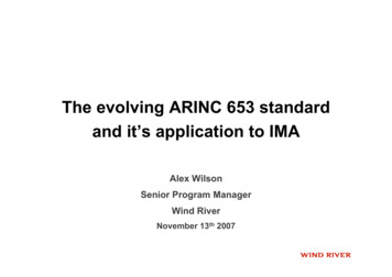
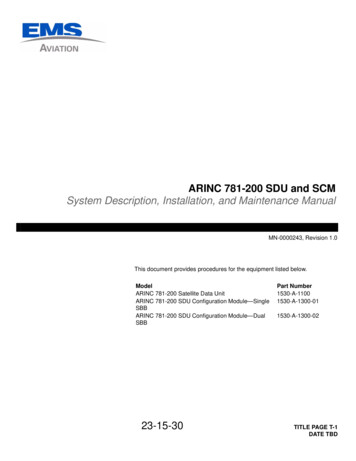
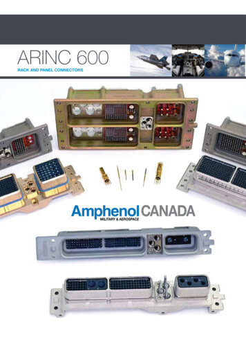
Next Gen ARINC 600 Stamped & Formed ContactsIntroduction600Introducing Amphenol Canada'sARINC 600 Next GenerationStamped & Formed ContactsTechnology. Size 22 Sockets arenow available in stamped andformed designs in both PCB andCompliant styles.phenolAmNEXT GENERATIONEUCHSRoE/2002 / 95 /The Next Gen ARINC 600 is available to replace yourstandard inserts and contacts with this intelligentdesign. This will provide cost savings and25% reduction in weightThese inserts and contacts are fully tested and in compliance with all ARINC 600 specifications and RoHS compliant.The contacts are designed using stamped and formed method with overmolding technology. They are completely inter-changeableand mateable with all existing Size 22 contacts. Contact Amphenol Canada for more information.PRODUCT FEATURES High-speedCompactDurableLow -costFilteredCUSTOMIZATIONConsult Amphenool Canada for additoinalinformation on custom applications.4Contact Amphenol Canada for more information at 416-291-4401 www.amphenolcanada.comDownload 2D drawings & 3D models using our online configurator.
Next Gen ARINC 600CANADAThe Next Generation of high-quality ARINC 600 interconnectFEATURES MECHANICAL Shell: Aluminum allo per SAE QQA. Shell Plating: Nickel, yellow iridite or chem film Contact: High performance copper alloy with 50μ" gold plating in mating area.Tin dipped contacts with optional gold plating available Insulator: Thermoplastic overmolded wafersNEXT GENERATION 600 Intermateable with existing plugs24% weight savingLower costHigh precision stamped and formed andselectively plated, size 22 contactsAvailable in PC Tail, press-fit compliance tailOvermolded wafer inserts to address humidityperformance and to eliminate potential solder wicking issuesRear removable contacts in rows of 10Interchangeable inserts with existing shellsEquivalent electrical performance of conventional designRoHS compliantUS patent #9,362,638ENVIRONMENTAL Temperature Range: -65 to 125 C High Temperature Tolerance: 1000 hrs min. at 125 C Process Temperatures: 270 C for 10 sec. wave solder260 C for 2 min. vapor phase Salt Spray: per MIL-STD-1344, method 1001, cond. B Humidity: per MIL-STD-1344, method 1002.1, type IIELECTRICAL Dielectric Withstand Voltage: Sea Level-1500 Vrms, 15,000 m: 500 VrmsVoltage Rating: 500 Vrms max.;125 Vrms at 15,000 mInsulation Resistance: 5.0 GW min. at 500 VdcSize 22 Contact Current Rating: 5.0 Adc, continuousContact Resistance: per MIL-STD-1344, method 3004-1APPLICATIONSCommercial Navigation/Radar Engine Controls Airframe & Landing Gear In-Flight Entertainment (IFE)Military Tactical/Mission Systems Power Distribution & Control Weapons Systems Avionics Mission Systems Radar Engine Controls Airframe & Landing Gear Weapons SystemsMContact Amphenol Canada for more information at 416-291-4401 www.amphenolcanada.comDownload 2D drawings & 3D models using our online configurator.5
How to Order - Next Generation Board Mount Receptacle'sFor Plugs and Standard Receptacles, please see page 92.Class3. ShellStyle4. Insert LayoutDesignatorPG 15-215. ShellType6. ConnectorMounting ModifierPG 22-247. PolarizingPositionPG 25-278. Contact ModifierMaterialAL331340001NGXPART #DESCRIPTIONNEXT GENERATIONSTEPS1. CONNECTOR SERIES2. CLASS3. SHELL SIZE4. INSERT LAYOUTPAGE 15-215. SHELL TYPEAARINC 600LPC TailMPC Tail & Rear Removable Crimp Contacts (Typically RF or power)1Max. contact capacity - 1602Max. contact capacity - 4003Max. contact capacity - 800phenolAmHSRoUE/2002 / 95 /The connector layout designator number represents the total number of contactsPAGES within the layout including waveguides. Consult Amphenol Canada Corporation15-21 for further availability of insert combinations. See pages 15-21.4Receptacle5Receptacle W/ Integral Stand-OffsRequired for Press-Fit designs but can also be used on PC Tail Contacts6. MOUNTING MODIFIERPAGE 22-24PAGES See charts on pages 22- 24.22-24 Consult factory if other modifications are required.7. POLARIZING POSITIONPAGE 25-27PAGES Polarizing posts or keys not installed but supplied with connector see pages25-27 25-27.8. CONTACT MODIFIERMATERIAL6C1. ConnectorSeriesE600PART NUMBER KEYNGXS&F TAIL EXTENSIONNGA.250" PC TAIL, ALL CONTACTS INCLUDED EXCEPT RFNGB.375" PC TAIL, ALL CONTACTS INCLUDED EXCEPT RFG & T Options require Shell Type '5 w/ Integrated Stand-Offs'NGG.040" (1.02MM) Press Fit - GOLD, ALL CONTACTS INCLUDED, EXCEPT RFNGT.040" (1.02MM) Press-Fit - TIN, ALL CONTACTS INCLUDED, EXCEPT RFContact Amphenol Canada for more information at 416-291-4401 www.amphenolcanada.comDownload 2D drawings & 3D models using our online configurator.
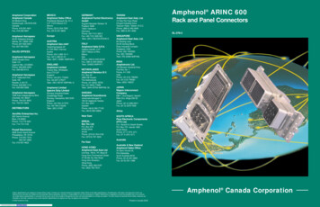
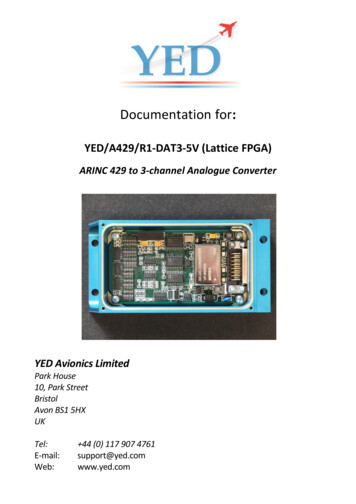
ARINC 600 NEXT GENERATIONCANADAShell Size 3RECEPTACLEPanel Cut-Outsee page 2860016.51 0.127.650 .005STAND-OFF DIMENSION32.841.293NEXT GENERATION73.30 0.1272.886 .00549.53 0.1271.950 .0052.16.085176.78 0.3816.960 .015161.29 0.1276.350 .005165.963 0.2546.534 .01054.10 0.1272.130 .0059.14 0.127.360 .00582.80 0.3813.260 .01511.557 0.127.455 .0052.79 0.127.110 .0051.52 0.127.060 .0054.724 0.05.186 .0026.807 0.127.268 .0053.18 0.127.125 .005MContact Amphenol Canada for more information at 416-291-4401 www.amphenolcanada.comDownload 2D drawings & 3D models using our online configurator.7
How to Order - ARINC 600PART NUMBER KEY1. ConnectorSeries2.Class3. ShellStyle4. Insert LayoutDesignatorPG 15-215. ShellType6. MountingModifierPG 22-247. PolarizingPositionPG 25-278. Contact ModifierMaterialAD331330001OOAARINC 600DENon-environmental (rear release, crimp contacts)ARINCF2. CLASSYJ4. INSERT LAYOUTPAGE 15-215. SHELL TYPE123phenolAmRoHS Environmental (rear release, crimp contacts)Non-environmental (front release, solder and wrap post #22 contacts, rearrelease all others).Same as E, less O-rings on plug sideEnvironmental (O-ring is used to seal between connector shell and insulators)with rear release, crimp contacts.All positions front release (except coax/triax)HSRoUE/2002 / 95 /All positions front release (all sizes)Max. contact capacity - 160Max. contact capacity - 400Max. contact capacity - 800The connector layout designator number represents the total number of contactsPAGES within the layout including wave guides. Consult Amphenol Canada Corporation15-21 for further availability of insert combinations. See pages 15-21.3Plug (rack side)4Receptacle (box side)6. MOUNTING MODIFIERPAGE 22-24PAGES See charts on pages 22 -24.22-24 Consult factory if other modifications are required.7. POLARIZING POSITIONPAGE 25-27PAGES Polarizing posts or keys not installed but supplied with connector see pages25-27 25-27.8. CONTACT MODIFIERMATERIAL8CS3. SHELL SIZE PAGE 9-11DESCRIPTIONE6001. CONNECTOR SERIESPART #CSTEPSOORear release, crimp, signal and power contacts supplied with connector(when applicable)FOContacts not supplied with connector (FO not stamped on connector)SAFront release .025 (0.63) D. x .150 (3.81) solder post and crimp, rear releasepower contacts (when applicable) supplied installed in connectorSBFront release .025 (0.63) D. x .250 (6.35) solder post and crimp, rear releasepower contacts (when applicable) supplied installed in connectorSCFront release .025 (0.63) D. x .375 (9.53) solder post and crimp, rear releasepower contacts (when applicable) supplied installed in connector.SDFront release .025 (0.63) D. x .500 (12.7) solder post and crimp, rear releasepower contacts (when applicable) supplied installed in connectorWAFront release .025 (0.63) Sq. x .250 (6.35) (1 wrap) wrap post and crimp, rearrelease power contacts (when applicable) supplied installed in connectorWBFront release .025 (0.63) Sq. x .375 (9.53) (2 wraps) wrap post and crimp, rearrelease power contacts (when applicable) supplied installed in connectorWCFront release .025 (0.63) Sq. x .500 (12.7) (3 wraps) wrap post and crimp, rearrelease power contacts (when applicable) supplied installed in connectorWDFront release .025 (0.64) Sq. x .641 (16.28) (3 wraps) wrap post and crimp, rearrelease power contacts (when applicable) supplied installed in connectorContact Amphenol Canada for more information at 416-291-4401 www.amphenolcanada.comDownload 2D drawings & 3D models using our online configurator.
Dimensional DrawingsCANADAShell Size 1PLUGPanel Cut-Outsee page 2860027.940 0.2541.100 .0104.724 0.051.186 .002161.290 0.1276.350 .005177.292 0.3816.980 .015165.964 0.2546.534 .010#2-56 UNCSCREWS withLOCKWASHERS(10 PLCS)#4-40THREADEDINSERTS(6 PLCS)35.611 MAX1.402 MAXTO GROMMET FACE27.991 MAX1.102 MAXTO REAR INSERT FACEARINC30.099 0.1271.185 .005166.751 0.2546.565 .010POLARIZATIONKEY POST3.759 0.076.148 .003MOUNTING HOLES(4 PLCS)63.754 0.2542.510 .0101.524 0.127.060 .0059.652 0.127.380 .00516.510 0.127.650 .0053.302 0.127.130 .0054.724 0.051.186 .0023.175 0.127.125 .00513.843 0.127.545 .0055.080 0.127.200 .0059.525 0.254.375 .010RECEPTACLEPanel Cut-Outsee page 2825.400 0.2541.000 .0104.724 0.051.186 .0023.048 0.127.120 .005PCB MOUNTINGLUGS (3 PLCS)39.50 MAX1.555 MAX3.175 0.127.125 .0054.724 0.051.186 .00238.89 MAX1.531 MAX188.976 0.3817.440 .015146.558 0.1275.770 .005161.290 0.1276.350 .005152.4 0.1276.00 .00531.01 MAX1.221 MAX#4-40 UNCTHREADEDINSERTS(6 PLCS)1.524 0.127.060 .005POLARIZATIONKEYWAY52.832 0.1272.080 .0059.144 0.127.360 .0052.794 0.127.110 .00516.510 0.127.650 .0054.724 0.051.186 .002160.020 0.2546.300 .01044.450 0.1271.750 .00516.510 0.254.650 .0109.525 0.254.375 .01035.636 0.2541.403 .01021.463 0.127.845 .005#2-56 UNCSCREWS withLOCKWASHERS(10 PLCS)3.810 0.127.150 .005MOUNTING HOLES(4 PLCS)13.335 0.254.525 .01022.860 0.254.900 .010* Indicates area where “AMPHENOL”, catalog number and date code will be ink stamped per9-5788-3. Dimensions are shown in inches, (mm). All dimensions for reference only.Contact Amphenol Canada for more information at 416-291-4401 www.amphenolcanada.comDownload 2D drawings & 3D models using our online configurator.M9
Dimensional DrawingsShell Size 2PLUG600Panel Cut-Outsee page 28ARINC45.720 0.2541.800 .01036.220 0.1271.426 .00530.099 0.1271.185 .005#4-40 UNCSCREWS withLOCKWASHERS(10 PLCS)35.610 MAX1.402 MAXTO GROMMET FACE161.290 0.1276.350 .00527.990 MAX1.102 MAXTO REAR INSERT FACE177.292 0.3816.980 .015165.964 0.2546.534 .010POLARIZATIONKEY POST3.759 0.076.148 .003MOUNTING HOLES(10 PLCS)54.102 0.1272.130 .0051.524 0.127.060 .0059.652 0.127.380 .0053.302 0.127.130 .0057.315 0.127.288 .0054.724 0.051.186 .0023.175 0.127.125 .00516.510 0.127.650 .0056.274 0.051.247 .0025.740 0.127.226 .0053.099 0.051.122 .002RECEPTACLEPanel Cut-Outsee page 2845.720 0.2541.800 .01036.220 0.1271.426 .00516.510 0.127.650 .005#4-40 UNCSCREWS withLOCKWASHERS(10 PLCS)38.89 MAX1.531 MAX176.784 0.3816.960 .015161.290 0.1276.350 .005POLARIZATIONKEYWAY31.01 MAX1.221 MAX165.964 0.2546.534 .0103.759 0.076.148 .003MOUNTING HOLES(10 PLCS)54.102 0.1272.130 .0051.524 0.127.060 .0059.144 0.127.360 .0052.794 0.127.110 .00511.557 0.127.455 .0053.175 0.127.125 .0054.724 0.051.186 .002* Indicates area where “AMPHENOL”, catalog number and date code will be ink stamped per9-5788-3. Dimensions are shown in inches, (mm). All dimensions for reference only.10Contact Amphenol Canada for more information at 416-291-4401 www.amphenolcanada.comDownload 2D drawings & 3D models using our online configurator.6.807 0.127.268 .005
Dimensional DrawingsCANADAShell Size 3PLUGPanel Cut-Outsee page 2849.530 0.1271.950 .00535.61 MAX1.402 MAXTO GROMMET FACE177.546 0.3816.990 .015165.963 0.2546.534 .010161.290 0.2546.350 .01027.99 MAX1.102 MAXTO REAR INSERT FACE#4-40 UNCSCREWS withLOCKWASHERS(17 PLCS)169.113 0.1276.658 .005POLARIZATIONKEY POSTARINC30.099 0.1271.185 .00573.304 0.1272.886 .00560016.510 0.127.650 .00582.804 0.3813.260 .0153.759 0.076.148 .003MOUNTING HOLES(14 PLCS)54.102 0.1272.130 .0051.524 0.127.060 .0059.643 0.127.380 .0053.175 0.127.125 .0057.320 0.127.288 .0056.274 0.051.247 .0024.724 0.051.186 .0023.302 0.127.130 .0055.740 0.127.226 .0053.099 0.051.122 .002RECEPTACLEPanel Cut-Outsee page 2816.510 0.127.650 .00582.804 0.3813.260 .01573.304 0.1272.886 .00549.530 0.1271.950 .005#4-40 UNCSCREWS withLOCKWASHERS(17 PLCS)38.89 MAX1.531 MAX176.784 0.3816.960 .015161.290 0.1276.350 .005POLARIZATIONKEYWAY31.01 MAX1.221 MAX165.964 0.2546.534 .0103.759.148MOUNTING HOLES(14 PLCS)54.1022.1301.524 0.127.060 .0059.144 0.127.360 .0052.794 0.127.110 .00511.557 0.127.455 .0053.175 0.127.125 .0054.724 0.051.186 .0026.807 0.127.268 .0054.686.1854.724 0.051.186 .002* Indicates area where “AMPHENOL”, catalog number and date code will be ink stamped per 9-5788-3.Dimensions are shown in inches, (mm). All dimensions for reference only.Contact Amphenol Canada for more information at 416-291-4401 www.amphenolcanada.comDownload 2D drawings & 3D models using our online configurator.M11
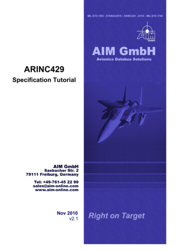
Insert ArrangementsQSize 1 Signal (A/B)ARINC600Size 1 (A/B)C TC QTYSizeQTYSizeQTYSizeQTYSizeQTYSizeQTY48Q48 C, T8122016282228 C, 22420Size 1 Power izeQTYSizeQTYSizeQTYSize38Q4122166121216 F11225 C, YSizeQTYSizeQTYSize3126163020402214201620C COAX12C TT TWINAX OR TRIAXF FIBERQ QUADRAX(6)6(12)12F12Note: Inserts are interchangable betweenCoax, Twinax, and Triax contactsContact Amphenol Canada for more information at 416-291-4401 www.amphenolcanada.comDownload 2D drawings & 3D models using our online configurator.
Insert ArrangementsCANADASize 2 & 3 (A/B)C TC T(4)QC NK(2)QTYSizeQTYSizeQTYSizeQTYSizeQTYSizeQTY21 C, T41 C, T108 C, T118Q1212516 F6002C22T2ARINCQC TF QC YSizeQTYSizeQTYSize121610161216 F24121022351668Q88 C, T88QF(20)20F12Q8(24)24(28)28C828T8C TC T101688 C, TQC Size3616F4720602070226222701628 C, T11 C,T616128 C,T48QC e10022118221182211022120221502252028 C, T21Q620616512516C COAXT TWINAX OR TRIAXF FIBERQ QUADRAXNote: Inserts are interchangable between Coax,Twinax, and Triax contactsContact Amphenol Canada for more information at 416-291-4401 www.amphenolcanada.comDownload 2D drawings & 3D models using our online configurator.M13
Insert ArrangementsSize 2 & 3 (C)C TC TQC )6Q6(6)QTYSizeQTYSizeQTYSizeQTYSizeQTYSize68Q68 C, T52011648 C, T418Q2516 FARINC600QC TC YSizeQTYSizeQTYSize316102242028 C, T2124121216 F412 C, T1216 F28Q111616121648 C, TFFQ(24)24C424T4(24)QTYSize202048 C, SizeQTYSize2416 0221621628Q4201228 C, T116C T1434Size20T128 C, TQ(16)C COAX2018C4Q218T4Q2QTYC TSize4C TSize12QTYF(15)5 C, T11Q217F12C217F12T2QTY2(13)C T11C411T44QTWINAX OR TRIAXQF FIBERQ QUADRAXNote: Inserts are interchangable between Coax,Twinax, and Triax contactsContact Amphenol Canada for more information at 416-291-4401 www.amphenolcanada.comDownload 2D drawings & 3D models using our online configurator.A
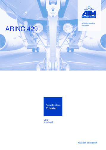
Insert Layout DesignatorCANADASize 1PART NUMBER KEY1. ConnectorSeries2.Class3. ShellStyle4. Insert LayoutDesignatorPG 15-215. ShellType6. MountingModifierPG 22-247. PolarizingPositionPG 25-278. Contact ModifierMaterialAD331330001OO600SIZE 1 ARINC 600INSERTLAYOUTDESIGNATORSHELL CAVITY INSERT 5C21301306030T240160160606040AARINC# OFCONTACTSBCMContact Amphenol Canada for more information at 416-291-4401 www.amphenolcanada.comDownload 2D drawings & 3D models using our online configurator.15
Insert Layout DesignatorSize 2ARINC600SIZE 2 ARINC 60016SIZE 2 ARINC 600# 12 853413C2595913C2Shell Cavity Insert Position# QShell Cavity Insert 212F5C213C211Q213C213C2Contact Amphenol Canada for more information at 416-291-4401 www.amphenolcanada.comDownload 2D drawings & 3D models using our online configurator.
Insert Layout DesignatorCANADASize 2SIZE 2 ARINC 600SIZE 2 ARINC 3459Shell Cavity Insert Position# C28559100DUMMY100EMPTY343459858585856T66T6100Shell Cavity Insert PositionContact Amphenol Canada for more information at 416-291-4401 www.amphenolcanada.comDownload 2D drawings & 3D models using our online configurator.ARINCINSERTLAYOUTDESIGNATOR600# ofcontactsM17
Insert Layout DesignatorSize 2ARINC600SIZE 2 ARINC 60018SIZE 2 ARINC 600# 17F12T246Q21003420Q4Shell Cavity Insert Position# 10085100Shell Cavity Insert PositionConta
Next Gen ARINC 600 Stamped & Formed Contacts Introduction The Next Gen ARINC 600 is available to replace your standard inserts and contacts with this intelligent design. This will provide cost savings and 25% reduction in weight These inserts and contacts are fully tested and in compliance with all ARINC 600 specifications and RoHS compliant.