Transcription
Rapid Prototyping&Rapid ToolingCorso di Sistemi integrati di Produzione A.A.2004-05Prof. G. A. Berti
Rapid Prototyping achievements Reduction in prototyping times (from weeks to days) Reduction in prototyping costs (from thuousands to hundreds ) Increase of the possible design iterations (from 2-3 to 8-9) Increase of possible form, fit, function testsShorter design cycleReduced Time-to-Market
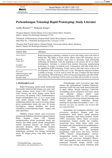
Rapid Prototyping12Computer modelMechanical modelVisual model34Production productMechanical functional model
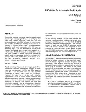
Rapid Prototyping MarketRP Machines production2001 3,55 Millions of models producedworldwideRP Machines installation 400 Service providers 8000 Machines sold since 1993Sectors of application
Useful Conditions for RP Single unique item or small number of copies needed Shape of object is in computer form Shape is too complex to be economically generatedusing conventional methods
Rapid Prototyping Technologies Six basic commercial technologies:StereoLithography (SL)Laminated Object Manufacturing (LOM)Selective Laser Sintering (SLS)Fused Deposition Modeling (FDM)Solid Ground Curing (SGC)Inkjet technologies (3D Plotting, MJM, 3DP.)
Rapid Prototyping ExamplesExamples of parts made by rapid prototyping processes.
Rapid Prototyping Examples / 2
Characteristics of Rapid Prototyping TechnologiesTABLE 19.1Supply phaseLiquidProcessStereolithographySolid-based e yer creationtechniqueLiquid layer curingLiquid layer curingand millingExtrusion of meltedpolymerDroplet depositionLayer of powder andbinder dropletdepositionLayer of powderDeposition of sheetmaterialPhase change cation bycoolingSolidification bycoolingNo phase changeLaser drivensintering melting andsolidificationNo phase changeMaterialsPhotopolymers (acrylates,epoxies, colorable resins,filled resins)PhotopolymersPolymers(ABS,polyacrylate, etc.),wax, metals and ceramicswith binder.Polymers, waxCeramic, polymer and metalpowders with binder.Polymers, metals withbinder, metals, ceramicsand sand with binder.Paper, polymers.
StereolithographySL 3D Systems, Valencia, CApatent 1986, beginning of RPphotopolymerization using UV laseraccuracy 0.025 mmepoxies, acrylates
Stereolithography SL
StereolithographySchematic illustration of the stereolithography process. Source: Ultra Violet Products, Inc.
Stereolithography SL
Stereolithography Machines
Stereolithography Process
SL Applications
SL Applications
Stereo-lithographyThe computational steps in producing astereolithography file.a)b)c)d)Three-dimensional description ofpart.The part is divided into slices (onlyone in 10 is shown).Support material is planned.A set of tool directions isdetermined to manufacture eachslice.
RP Sequence CAD solid model‘.STL’ fileSlicing the fileFinal build fileFabrication of partPost processing
CAD Solid Model Solid model or closed surface model required
‘.STL’ File Software generates a tessellated objectdescription File consists of the X, Y, Z coordinates of thethree vertices of each surface triangle, withan index to describe the orientation of thesurface normal Support generation to hold overhung surfacesduring build
Slicing the File Series of closely spaced horizontal planes aremathematically passed through the .stl file Generate a ‘.sli’ file : a series of closely spaced2D cross-sections of the 3D object Typical Z thickness 0.006” (0.150 mm) Other Parameters chosen fn(RP technology)
Common Support Structures(a)(b)A part with a protruding section which requires support material.Common support structures used in rapid-prototyping machines.Source: P.F. Jacobs, Rapid Prototyping & Manufacturing: Fundamentals ofStereolithography. Society of Manufacturing Engineers, 1992.
partFinal Build FilesupportsPart slicedSupports slicedRP technology parameters set (layer thickness, scan speed, )Send file to RP machine
Fabrication of PartModels built on stereolithography apparatus.Part and supports shown attached to platform.
Post-processingRemoval of part from platformRemoval of supports from partCleaning of part (wiping, rinsing, . )Finishing part (sanding, polishing, )
Laminated Object ManufacturingLOM Cubic Technologies, Carson, CA (former Helisys)patent 1985cross-sectional cutouts fused togetheraccuracy 0.076 mmpaper, plastic
Laminated Object ManufacturingLOM
Laminated Object Manufacturing LOM
Laminated-Object Manufacturing(a)(a)(b)(b)Schematic illustration of the laminated-object-manufacturing process. Source: Helysis, Inc.Crankshaft-part example made by LOM. Source: After L. Wood.
Helisys LOM 1015
LOM Applications
Selective Laser SinteringSLS 3D Systems, Valencia, CA (former DTM)patent 1989, Carl Deckard’s master thesisfusing polymeric powders with CO2 laseraccuracy 0.040 mmpolycarbonate, nylon, wax, glass-filled nylon,powder coated metals or ceramics
Selective Laser Sintering
Selective Laser Sintering SLS
Selective Laser SinteringSchematic illustration of the selective laser sintering process. Source: After C.Deckard and P.F. McClure.
Selective Laser Sintering
SLS Applications
Fused Deposition ModelingFDM Stratasys, Eden Prarie, MNpatent 1992robotically guided fiber extrusionaccuracy 0.127 mmcasting and machinable waxes, polyolefin,ABS, PC
Fused Deposition ModelingFDM
Fused Deposition Modeling FDM
Fused-Deposition-Modeling(a)(b)(a) Schematic illustration of the fused-deposition-modeling process.(b) The FDM 5000, a fused-deposition-modeling-machine. Source: Courtesy of Stratysis, Inc.
FDM Machines
FDM Applications
Solid-Base CuringSBC Cubital, Troy, MI (Failed 2000) patent 1991 photopolymerization using UV light passingthrough a mask accuracy 0.510 mm Photopolymers
Solid-Base CuringSchematic illustration of the solid-base-curing process. Source: After M. Burns,Automated Fabrication, Prentice Hall, 1993.
Solid-Base Curing
3D Plotting Solidscape Inc., Marrimack, NH Inkjet technology Dual heads deposit part material(thermoplastic) and support material (wax) Accuracy 0.025 mm (layers 0.013 mm) Thermoplastic (build)Wax, fatty esters (support)
3D Plotting
3D Plotting
3D Plotting Applications
Multi-jet ModellingMJM Accelerated Tech., 3D Systems, Solidimension Ltd Inkjet technology Multiple heads deposit support material and partmaterial cured immediately by UV light Accuracy 0.020 mm Photopolymers
Multi-jet ModellingMJM
MJM Applications
3D Printing 3DP Z Corporation, Burlington, MA Printing head deposits binder solution onbuild powder Accuracy 0.076 mm Waxes, acrylates, epoxies
3D PrintingSchematic illustration of the three-dimensional-printing process. Source: After E. Sachs and M. Cima.
3D Printing
3D Printing Applications
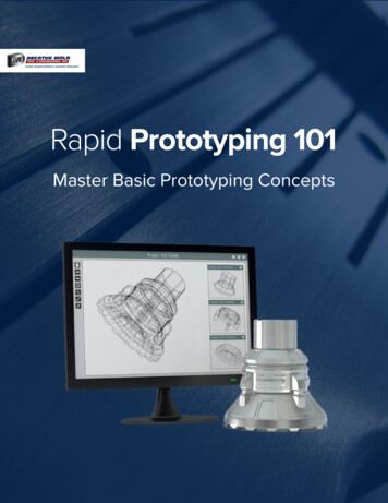
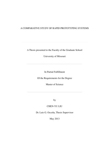
Investment CastingManufacturing steps forinvestment casting thatuses rapid--prototypedwax parts as blanks.This approach uses aflask for the investment,but a shell method canalso be used. Source:3D Systems, Inc.
ManufacturingExample: Investment Casting Wax pattern build fromStratasys multi-jet droplettechnique Pattern used ininvestment casting tofabricate metal ring Allows for designmodifications and quickturnaround of metal band
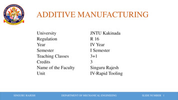
Sand Casting Using Rapid-Prototyped PatternsManufacturing steps in sand casting that uses rapid-prototyped patterns.Source: 3D Systems, Inc.
Sand Casting (continued)
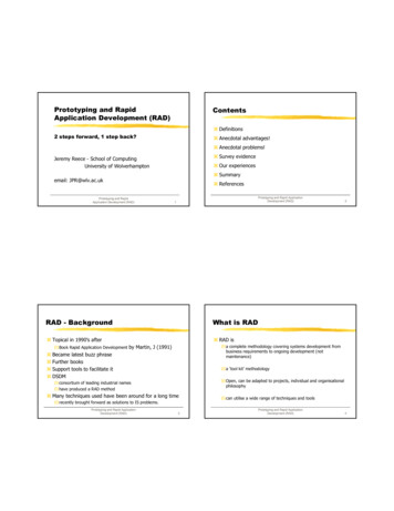
Rapid ToolingRapid tooling for a rear-wiper-motor cover
Benefits to RP TechnologiesVisualization, verification, iteration, and design optimizationCommunication tool for simultaneous engineeringForm-fit-function testsMarketing studies of consumer preferencesMetal prototypes fabricated from polymer partsTooling fabricated from polymer parts
Conclusions Rapid prototyping is a new tool, which usedappropriately .– allows the manufacturing enterprise to runsmoother– increases throughput and product quality New uses and applications are discoveredeveryday Future areas include new materials directlydeposited (metals, ceramics)
Investment Casting Manufacturing steps for investment casting that uses rapid--prototyped wax parts as blanks. This approach uses a flask for the investment, but a shell method can also be used. Source: 3D Systems, Inc.