Transcription
A COMPARATIVE STUDY OF RAPID PROTOTYPING SYSTEMSA Thesis presented to the Faculty of the Graduate SchoolUniversity of MissouriIn Partial FulfillmentOf the Requirements for the DegreeMaster of SciencebyCHEN-YU LIUDr. Luis G. Occeña, Thesis SupervisorMay 2013
The undersigned, appointed by the Dean of the Graduate School, have examined thethesis entitledA COMPARATIVE STUDY OF RAPID PROTOTYPING SYSTEMSPresented by Chen-Yu LiuA candidate for the degree of Master of ScienceAnd hereby certify that in their opinion it is worthy of acceptance.Professor Luis G. OcceñaProfessor Cheng Alec ChangProfessor Sherif El-GizawyProfessor Michael Klote
ACKNOWLEDGEMENTSI would first like to thanks my advisor Professor Dr. Luis G. Occeña for givingme the opportunity to improve my knowledge, for all his guidance and tirelessinstruction throughout my graduate studies at the University of Missouri, Columbia.I would also like to express my appreciation to Mr. Michael Klote for hissupport, encouragement, dedication, all his helps, and providing insight into the RapidPrototyping process.Finally, grateful acknowledgement is made to my parents for their support andeverything they gave to me.ii
Table of ContentsACKNOWLEDGEMENTS . iiLIST OF FIGURES . viLIST OF TABLES .viiiABSTRACT. xChapter 1: INTRODUCTION . 11.1 Rapid Prototyping . 11.2 Selective Laser Sintering (SLS) . 41.3 PolyJet . 61.4 Fused Deposition Modeling (FDM). 81.5 3D Printing (3DP) . 101.6 Objectives . 12Chapter 2: LITERATURE REVIEW . 152.1 Dimensional Accuracy . 162.2 Mechanical Properties . 19Chapter 3: METHODOLOGY. 223.1 Experiment scheme . 223.2 Materials and sample preparation . 23iii
3.3 Shape of test specimen . 263.4 Dimension measurement . 283.5 Tensile testing . 293.6 Water absorption . 303.7 Shore Hardness . 333.8 Microscopy . 35Chapter 4 RESULTS AND ANALYSIS . 364.1 Dimensional accuracy . 364.1.1 SLS Dimensional accuracy . 374.1.2 PolyJet Dimensional accuracy . 414.1.3 FDM Dimensional accuracy . 454.1.4 3DP Dimensional accuracy . 504.1.5 Summary – Dimensional accuracy . 564.2 Tensile Properties . 594.2.1 SLS Tensile Properties . 594.2.2 PolyJet Tensile Properties . 634.2.3 FDM Tensile Properties . 674.2.4 3DP Tensile Properties . 704.2.5 Summary – Tensile Properties . 74iv
4.3 Water absorption . 794.4 Shore Hardness . 834.5 Microscopy and Analysis . 88Chapter 5: CONCLUSION AND FUTURE WORK . 915.1 Conclusion . 915.2 Future work . 95REFERENCES . 97v
LIST OF FIGURESFigurePage1.Schematic view of SLS process . 52.Schematic view of PolyJet process . 73.Schematic view of FDM process . 94.Schematic view of 3DP process . 115.Specimens in three build orientations in each RP system . 266.Shape of test specimen for tensile testing (mm) . 277.Four measurement points on the specimen (mm) . 298.The test specimen is clamped by the jaws of the test machine . 309.Specimens for water absorption sealed in a plastic bag . 3210.OHAUSE ScoutPro SP200 balance . 3211.ASTM Type D Ergo Durometer . 3412.Measurement points for Shore hardness . 3413.Stereo Microscope MEIJI Techno EMZ-5TR . 3514.Dimensional Accuracy of four measurement points in SLS . 3915.AVG Dimensional Accuracy of three build orientations in SLS . 3916.Dimensional Accuracy of four measurement points in PolyJet . 43vi
17.AVG Dimensional Accuracy of three build orientations in PolyJet . 4318.Dimensional Accuracy of four measurement points in FDM . 4719.AVG Dimensional Accuracy of three build orientations in FDM . 4720.Dimensional Accuracy of four measurement points . 5221.Dimensional Accuracy of four measurement points . 5222.AVG Dimensional Accuracy of three build orientations. 5323.AVG Dimensional Accuracy of three build orientations. 5324.Dimensional Accuracy . 5825.SLS Tensile Strength . 6126.PolyJet Tensile Strength . 6527.FDM Tensile Strength . 6828.3DP Tensile Strength . 7229.Tensile Strength . 7530.Elongation . 7631.Elongation at Break . 7732.FDM specimen at 10 times magnification . 81vii
LIST OF TABLESTablePage1.Current RP systems in the market . 32.Rapid Prototyping systems at the University of Missouri, Columbia . 233.Materials used in RP systems at the University of Missouri, Columbia . 244.Three build orientations . 255.Dimensions of tensile test specimen (ASTM D638-10 Type IV) . 276.Measured results in SLS . 387.Measured results in PolyJet . 428.Measured results in FDM . 469.Measured results in 3DP . 5110. Dimensional Accuracy Summary . 5711. SLS Tensile Properties. 6012. PolyJet Tensile Properties . 6413. FDM Tensile Properties . 6814. 3DP Tensile Properties . 7115. Tensile Properties . 7816. The relative rate of Water Absorption in the four RP systems . 8117. Shore Hardness . 85viii
18. Stereo microscope pictures of the fracture surfaces of tensile testing specimens. 9019. Experiment results summary (Boldface indicate the best performance) . 94ix
ABSTRACTA general comparative study of the literature sources across different RapidPrototyping systems and performance in different build orientations has shown that thepublications are few in number. This research aims to provide general informationincluding dimensional accuracy and tensile properties for different build orientations,and relative water absorption and Shore hardness properties between different RapidPrototyping systems. Test specimens were fabricated in four popular commercial RapidPrototyping systems: Selective Laser Sintering (SLS), PolyJet, Fused DepositionModeling (FDM), and 3D Printing (3DP) at the University of Missouri, Columbia. Theresults can be used as a preliminary guide to help users determine optimal strategies forrapid prototyping system selection.x
Chapter 1: INTRODUCTION1.1 Rapid PrototypingRapid Prototyping (RP) is a process which fabricates a part layer-by-layer. Thistechnology has also been referred to as layered manufacturing, additive manufacturing,and rapid manufacturing. Rapid prototyping automatically generates physical objectsdirectly from 3D CAD data by depositing material layer by layer, unlike conventionalmethods, where material is removed to obtain the final object.Fundamentally, the development of Rapid Prototyping technology can be splitinto four primary aspects: Input, Method, Material, and Applications [1]. Input refersto the electronic information required to describe the physical object with numericaldata. In the last decade, a number of techniques for Rapid Prototyping have beendeveloped. There are several methods employed in different Rapid Prototypingsystems provided by each vendor. The materials used in different rapid prototypingsystems are also varied. The initial state of these materials can be either a solid, liquid,or powder state. Applications can be grouped into design, education, engineering andanalysis, and manufacturing and tooling [1]. A wide range of industries can benefitfrom rapid prototyping technology.1
Rapid Prototyping is the term that has been coined for processes that canproduce an accurate model from a computer-aid design (CAD) database without anyadditional tooling or machining [2]. Because Rapid Prototyping can build solid modelso quickly, it has revolutionized the way industries approach their productdevelopment cycles. With Rapid Prototyping, an engineer can design and buildprototype models within a small amount of time. The ability to quickly verify a designprevents the investment of time and money in a poorly conceived project orcomponent. The benefits provided by Rapid Prototyping include reduced lead timeand cost to produce components, improved ability to visualize design geometrydirectly, earlier detection and reduction of design errors, and optimized part design tomeet customer requirements. Also, Rapid Prototyping is advantageous in theelimination of waste and costly late design changes [3].In order to create a part using Rapid Prototyping techniques, several steps haveto be performed. All RP systems generally have similar process steps:1.Create a CAD model to describe the physical object.2.Convert the CAD model to a STereoLithography (STL) file format.3.File preprocessing: correct file errors, slice the model into cross-sectionallayers, and distribute model orientation.4.Build the prototype.2
5.Postprocessing: clean and remove excess material from the model.These steps are a generalization of Rapid Prototyping process, and each systemcan include its own individual steps. There are currently many Rapid Prototypingsystems in the market. According to Kruth [4], the material accretion technologiesmay be divided by the state of the prototype material before part formation. All RapidPrototyping systems can be categorized into (1) liquid-based (2) solid-based and (3)powder-based [1]. Table 1 shows a summarized category of RP systems. In thefollowing sections, Rapid Prototyping systems at the University of Missouri,Columbia: Selective Laser Sintering (SLS), PolyJet, Fused Deposition Modeling(FDM), and 3D Printing (3DP) will be discussed in detail.Table 1. Current RP systems in the market [1]Liquid-BasedStereolithography (SLA)Objet’s PolyJetCubital’s Solid Ground Curing (SGC)Ballistic Particle Manufacture (BPM)Solid-BasedLaminated Object Manufacturing (LOM)Fused Deposition Modeling (FDM)Powder-BasedSelective Laser Sintering (SLS)3D Printing (3DP)Laser Engineered Net Shaping (LENS)3
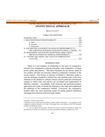
1.2 Selective Laser Sintering (SLS)The Selective Laser Sintering (SLS) process produces solid components using acarbon dioxide (CO2) laser to heat powdered materials layer by layer so that thesurface tensions of the grains are overcome and they fuse together. Before the powderis sintered, the entire chamber is heated to just below the melting point of the materialin order to minimize thermal distortion and facilitate fusion to the previous layer [5].The laser selectively fuses powdered materials by tracing the cross-sectional slicesfrom a 3D digital description of the part. The interaction of the CO2 laser beam withthe powder raises the temperature to the melting point, resulting in particle bonding,fusing the particles to themselves and the previous layer to form a solid [1]. The laserbeam with adjustable intensity fuses the powder only in areas defined by the part’sgeometry. The powder not melted or fused during processing serves as supportstructure. Therefore, there is no need to have support material in the SLS process.After each cross-section is completely drawn, the powder bed is lowered by one layerthickness, and an additional layer of powder is deposited via a roller mechanism ontop of the previous layer. The process: (1) new layer deposited, (2) laser beam trace,and (3) entire powder bed lowered is repeated until the part is complete. Figure 1shows SLS process in brief with a diagram.4
Figure 1. Schematic view of SLS process [6]After the SLS build process, the build chamber is moved to a post-processingstation. The loose powder simply falls away, and the SLS parts require somepost-processing such as sanding with high pressure air and glass bead mixture, andcleaning with pressurized air.There is a wide range of initial material available for the SLS system. Atpresent, nylon, nylon composites, polycarbonates, metals, sand, wax, and ceramics arein use [1, 7]. However, the materials employed by the system are sensitive to thedifferent heating and laser parameters and each material requires specified settings.5
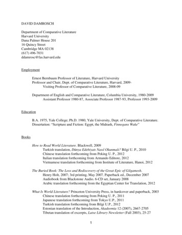
The products form the SLS system tend to have poorer surface finish due to therelatively large particle sizes of the powders used.1.3 PolyJetThe manufacturer, Objet Geometries, was the first company to successfully jetphotopolymer material using its patented PolyJet technology to produce a complexmodel from a 3D geometry file in early 2000 [8]. A composed printing head injects a20 μm thick layer of photopolymer material on the build tray only in the areas thatcorrespond to the cross-sectional profile from a 3D digital description of the part.Simultaneously, the photopolymer layer is cured by UV light after it is jetted, andeach layer is adjusted to 16 μm by a roller that is moved across the build trayimmediately after deposition [9]. The repeated addition and solidification ofphotopolymer material layers produces a solid three-dimensional model until it iscomplete. To avoid the collapse of structures during production, a gel-like supportmaterial, which is specially designed to support complicated geometries, is injectedtogether with the model material. When the model is completed, the support materialis easily removed by hand and water jetting to leave only the hardened photopolymermaterial. Figure 2 shows Objet’s PloyJet technology in brief with a diagram.6
Figure 2. Schematic view of PolyJet process [8]Objet’s PolyJet provides a wide variety of materials for different geometries,mechanical properties, and colors; use of the same support material for all modeltypes makes switching material easy and fast. Furthermore, PolyJet MatrixTechnology enables simultaneous jetting of different types of model materials. It canjet two distinct photopolymer model materials in preset combinations.7
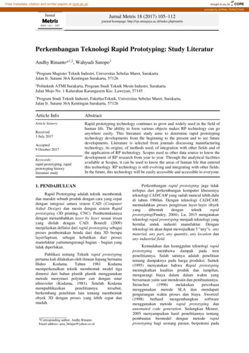
1.4 Fused Deposition Modeling (FDM)Scott Crump, the president and CEO of Stratasys Inc, developed the FusedDeposition Modeling (FDM) process in 1988 and the patent was awarded in the U.S.in 1992 [1, 3]. The FDM process fabricates parts by extruding semi-molten materialthought a extrusion head that traverses in X axis and Y axis to create each twodimensional layer of the part [10]. The movable extrusion head composed of twoextrusion nozzles: one for build material and the other for support material [1, 7, 11].This process can be seen in Figure 3. The extrusion head deposits a filament of moltenmaterial either build material or support material onto a foam base. The build materialis heated to 0.5 C above its melting point so that it solidifies about 0.1s after extrusionand cold welds to the previous layers [7]. In general, an outline of the perimeter of thepart is extruded from the head first and then the interior is raster filled by the extruderhead [10]. Once a layer is built, the platform lowers, and the extrusion head depositsanother layer. The machine continues to build the part layer by layer until it iscomplete. When the part is finished, it is removed from the machine and the supportmaterial need to move away to reveal the finished product. There are two types ofsupport material: Soluble support system and Break-Away Support System (BASS)[12]. It can be removed with specialized equipment utilizing water-based sodium8
hydroxide solution, or break it away by hand.Figure 3. Schematic view of FDM process [13]In the FDM process, there is also a large range of colors and materials available,such as investment casting wax and thermoplastic [7]. The material generally used is athermoplastic including ABS plastic, medical grade ABS (MABS), elastomers,polycarbonate, polyphenyl-sulfone (PPSF), and Ultem 9085 [1, 14]. The mainadvantages of using FDM technology are fabrication of functional parts, minimalmaterial wastage, ease of support material removal, and ease of material change [1].A disadvantage of using FDM technology is that the surface finish of the parts9
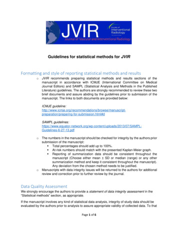
is worse than other rapid prototyping systems due to the resolution of the processwhich is dictated by the filament thickness [7, 15]. The other disadvantage is that thebuilding process is slow, as the whole cross-sectional area needs to be filled withbuilding material. Unpredictable shrinkage is also a disadvantage of using FDMtechnology. As the FDM process extrudes the build material from its extrusion headand cools them rapidly on deposition, stresses induced by such rapid coolinginvariably are introduced into the model. As such, shrinkages and distortions causedto the model built are a common occurrence and are usually difficult to predict [1].1.5 3D Printing (3DP)Z Corporation commercialized its first 3D Printer, the Z 402 System, based onthree-dimensional technology (3DP) in 1997 [1]. The core technology was inventedand patented at the Massachusetts Institute of Technology. It was subsequentlylicensed and further developed by Z Corporation. Z Corporation was acquired by 3DSystems on January 3, 2012 [16]. The 3D Printing (3DP) process is similar to theSelective Laser Sintering (SLS) process, but instead of using a CO2 laser to sinter thepowdered material, an ink-jet printing head deposits a liquid adhesive that binds thematerial. The 3D Printing machine has two pistons: one for feeding the powder and10
the other for lowering/raising the building chamber shown in Figure 4.Figure 4. Schematic view of 3DP process [17]The 3D Printing process begins with the powder supply being raised by a pistonand a leveling roller distributing a thin layer of powder to the top of the build chamber[17]. The multi-channel ink-jet printing head then deposits binder solution onto theloose powder, forming the first cross-section [1]. These regions of powder are gluedtogether wherever the binder is printed. The remaining powder remains loose andsupports the part during the process. When the cross-section is completed, the buildpiston is lowered, the powder feed piston is raised, and a new layer of powder is11
added on the previous layer by the leveling roller. The process is repeated and the partgrows layer by layer on the build piston until the part is finished. Finally the buildpiston is raised and the loose powder is brushed and the part removed [1]. 3D Printedparts are typically infiltrated with a hardener to improve strength and surface finish.The main advantages of using 3D Printing technology are color capability,shorter build times, and inexpensive raw materials when compared to other rapidprototyping systems [1, 6]. No support structures needed is also an advantage of 3DPrinting. The powder bed provides self-support to allow complex geometry to becreated. The disadvantages of using 3D Printing technology are the printed part isrelatively fragile compared to other rapid prototyping systems, the infiltrationpost-processing is needed, and the surface finish is relatively poor [6].1.6 ObjectivesRapid Prototyping is a fast growing technology that can substantially helpengineers shorten the time and decrease the cost of developing a new product from theinitial idea to production. There are also many restrictions with many rapidprototyping procedures, primarily in the number of available materials and theirproperties, which may differ significantly from the properties of end product material.12
The research objective of this thesis is to develop combined experiments and analysesapproach to compare the specimens fabricated in different build orientations anddifferent rapid prototyping systems. In this research, test specimens were made in fourpopular commercial rapid prototyping systems: SLS (EOS Formiga P100), PolyJet(Objet Eden 350V), FDM (Dimension Elite 3D Printer), and 3DP (Z CorporationSpectrum Z510). This research includes (1) Dimensional Accuracy: to providecomparative information of dimensional accuracy when specimens are fabricated inthree build orientations (Horizontal, Side, and Vertical) in each of four rapidprototyping systems. A comparative study of dimensional accuracy across differentrapid prototyping systems is also provided in this research (2) Tensile Property:provide a comparative study of tensile property based on specimens produced in threebuild orientations (Horizontal, Side, and Vertical) and four different rapid prototypingsystems (3) Water Absorption: provide information about the relative waterabsorption across different rapid prototyping systems will be included in this research(4) Shore hardness: the Shore hardness of test specimens fabricated in different rapidprototyping systems will be presented in this research. The lack of knowledge in theperformance of different build orientations across different rapid prototyping systemsis motivation for this investigation. The main objective of this research is to provideusers with a preliminary guide to help determine optimal strategies for rapid13
prototyping system selection.A literature review is presented in Chapter two to review and discuss previouswork performed by researchers on four rapid prototyping systems. In Chapter three,the experiment methodology is presented. In Chapter four, the experiment results ofdimensional accuracy, tensile property, water absorption, and Shore hardness arepresented and discussed. In Chapter five, the conclusions and future work arediscussed.14
Chapter 2: LITERATURE REVIEWRapid prototyping is a term that the manufacturing industry has struggled withfor many years. In the early day, layer-based rapid prototyping (RP) technologieswere mainly concerned with producing physical parts as quickly as possible from adesign concept, for the purpose of design verification [18]. The initial term,established by 3D Systems (Valencia, CA), was “StereoLithography,” orthree-dimensional printing. The growing field has been widely referred to in technicaland industrial publications as “Rapid Prototyping”.Nowadays, with the fast development of rapid prototyping technologies: moreavailable materials, with various mechanical properties to meet a variety ofapplications, and higher accuracy of parts produced, rapid prototyping technologieshave been used for fabrication of functional parts and tooling [19, 20]. As rapidprototyping parts are made by additive processes, they may have properties that arequite different from parts that are made by conventional manufacturing processes. It isdifficult to directly compare the many properties of rapid prototyping parts, as thesedepend not only on the material being used, but also on the direction in which theproperty is being measured. In this study, the properties: (1) dimensional accuracy, (2)15
tensile property, (3) water absorption, and (4) Shore hardness were investigated. Thefollowing sections will present previous work and literature resource related to thesetopics.2.1 Dimensional AccuracyDimensional accuracy of a rapid prototyping product is influenced by a specificrapid prototyping technique used, the material chosen, and the operating parametervalues. Due to different processes and materials used in rapid prototypingtechnologies, parts differ in their tendency to shrink or deform. In the paper byDurham et al. [21], the shrinkage of the Stereolithography (SLA) epoxy wassignificantly less than the Selective laser sintering (SLS) plastic material, and thesmall shrinkage of Stereolithography (SLA) resins was simple to predict and easy tocontrol.In 1997, D.T. Pham and R.S. Gault [7] presented and summarized differentrapid prototyping technologies. The paper presented an overview of rapid prototypingtechnologies and commented on their strengths and weaknesses. In this study, datasuch as layer thickness, system accuracy and speed of operations were given. Thefollowing rapid prototyping technologies were included in this paper.16
MaterialProcesses hy (SLA)Liquid thermal polymerization (LTP)Beam interference solidification (BIS)Solid ground curing (SGC)Holograhpic interference solidification (HIS)Electrosetting (ES)Ballistic particle manufacture (BPM)Fused deposition modelling (FDM)Three dimensional welding (3DW)Shape deposition manufacturing (SDM)Processes i
Rapid Prototyping is the term that has been coined for processes that can produce an accurate model from a computer-aid design (CAD) database without any additional tooling or machining [2]. Because Rapid Prototyping can build solid model so quickly, it has revolutionized the way industries approach their product .