Transcription
Version 5 Release 14STL Rapid PrototypingSTL Rapid PrototypingOverviewWhat's New?Getting StartedBasic Surface TessellationRepairing the MeshChecking the Mesh QualityUser TasksStarting the STL Rapid Prototyping WorkbenchUsing the KeyboardSTL filesImporting FilesExporting to STLSTL EditionActivating a Portion of a CloudRemoveSTL MeshMesh CreationSurface TessellationOffsetFlip EdgesSmoothing MeshesMesh CleanerFill HolesInteractive Triangle CreationDecimating MeshesOptimizing MeshesSTL OperationsMeshes MergeSplitTrimming or Splitting a MeshDisplay OptionsInformationInteroperabilityUpdating Your DesignUsing the Historical GraphCreating DatumsPoints in Generative Shape DesignManaging Geometrical SetsWorkbench DescriptionPage 1
STL Rapid PrototypingMenu BarCreation ToolbarsSTL FilesEditionMeshOperationsAnalysisAnalysis ToolbarsSpecification TreeGlossaryIndexVersion 5 Release 14Page 2
Version 5 Release 14STL Rapid PrototypingPage 3OverviewWelcome to the STL Rapid Prototyping User's Guide!This guide is intended for users who need to become quickly familiar with the product.This overview provides the following information: STL Rapid Prototyping in a Nutshell Before Reading this Guide Getting the Most Out of this Guide Accessing Sample Documents Conventions Used in this GuideSTL Rapid Prototyping in a NutshellSTL Rapid Prototypinghelps the stereolithography specialist to build and manage STL files.The STL Rapid Prototyping User's Guide has been designed to show you how to do that. Althoughstereolithography knowledge is not mandatory, it is recommended to have some technical background in thearea.Before Reading this GuidePrior to reading the STL Rapid Prototyping User's Guide, you are recommended to have a look at theInfrastructure User's Guide for information on the generic capabilities common to all products.Getting the Most Out of this GuideTo make the most out of this book, we suggest that a beginning user reads the Getting Started chapterfirst of all and the Workbench Description to find his way around the STL Rapid Prototyping workbench.Accessing Sample DocumentsTo perform the scenarios, sample documents are provided all along this documentation. For more informationabout this, refer to Accessing Sample Documents in the Infrastructure User's Guide.
Version 5 Release 14STL Rapid PrototypingWhat's New?New FunctionalitiesInteractive Triangle CreationCreates mesh triangles from points or edges.OptimizeImproves the homogeneity of meshes.Enhanced FunctionalitiesActivation, Remove Point, SplitA brush has been added for a quick and rough area selection.Mesh SmoothingDeviation statistics are now available.DecimationAn analysis option and a progress bar have been added.Page 4
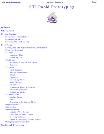
Version 5 Release 14STL Rapid PrototypingPage 5Getting StartedThe following tutorial aims at giving you a feel of what you can do with STL Rapid Prototyping. It provides a stepby-step scenario showing you how to use key capabilities.The main tasks proposed in the chapter are:Basic Surface TessellationRepairing the MeshChecking the Mesh QualityAll together this scenario should take 15 minutes to complete.The final cloud element will look like this:
STL Rapid PrototypingVersion 5 Release 14Page 6Creating a Basic Surface TessellationThe first task will show you how to enter the STL Rapid Prototyping workbench and create a basic surface tessellation.The only pre-requisites for this task is to have a current session running.1. Choose STL Rapid Prototyping from the Start/NC Manufacturing menu.The STL Rapid Prototyping workbench is displayed and ready to use.2. Open the GettingStartedSTL.CATPart from the samples directory. It is a hairdryer, made of surfaces, with a gapand a hole in it.
STL Rapid Prototyping3. Click the Surface Tessellate iconVersion 5 Release 14and select the hairdryer. Click Apply and OK.Page 7
STL Rapid PrototypingVersion 5 Release 14You can see clearly the hole and the gap in the tessellation.Page 8
Version 5 Release 14STL Rapid PrototypingRepairing the MeshThis task will show you how to repair a mesh.Use the mesh you have created in the previous task.Repairing the hole:1. Click the Fill Holes iconand select the mesh.The exterior edge of the model is displayed in red, with an "x" meaning this edge is not candidate for a filling.The two other edges in green with a "v" surround holes candidates for the filling.2. Place the cursor over the label of the long hole and call the contextual menu. Choose Not selected.Page 9
STL Rapid PrototypingVersion 5 Release 143. Click Apply and OK. The hole is filled:Repairing the gap:1. Click the Define a Mesh Area iconand select the mesh (Tessellation.1).2. Draw a trap around the gap and check the Inside Trap option.Page 10
Version 5 Release 14STL Rapid PrototypingPage 11Click Apply and OK. A portion of the mesh is activated:3. Click the Mesh Regeneration iconand select the mesh (Tessellation.1). Check the Constrained option.Click Apply and OK. A MeshCreation.1 element is created in the specification tree: the mesh on this portion has been regenerated.
STL Rapid PrototypingVersion 5 Release 14Page 124. Select the Tessellation.1 element in the specification tree and click the Activation icon. Push the Activate All button. Both meshes arenow active (we have changed MeshCreation.1 to pink). From the picture below you can see that they are complementary:
Version 5 Release 14STL Rapid Prototyping5. Click the Merge iconand select the two meshes:6. Click OK. A Meshes Merge.1 element is created in the specification tree. You have now a flawless mesh.Page 13
Version 5 Release 14STL Rapid PrototypingPage 14Checking the Mesh QualityThis task will show you how to quickly check the quality of the mesh.Use the mesh you have created in the previous task.1. Click the Display iconand select the Meshes Merge.1 mesh. The Cloud Display Optionsdialog box is displayed.The default option is Smooth. You can check : the Triangles option:
STL Rapid PrototypingVersion 5 Release 14 the Free Edges option: the Non-manifold Edges option: (none in our example) the Flat option:Page 15
STL Rapid PrototypingYou can combine all of them too.Version 5 Release 14Page 16
STL Rapid PrototypingVersion 5 Release 14User TasksStarting the STL Rapid Prototyping WorkbenchUsing the KeyboardSTL filesSTL EditionSTL MeshSTL OperationsDisplay OptionsInformationInteroperabilityManaging Geometrical SetsPage 17
STL Rapid PrototypingVersion 5 Release 14Page 18Opening the STL Rapid Prototyping WorkbenchThe first task will show you how to enter the STL Rapid Prototyping workbench and create a basic surface tessellation.The only pre-requisites for this task is to have a current session running.1. Choose STL Rapid Prototyping from the Start/NC Manufacturing menu.The STL Rapid Prototyping workbench is displayed and ready to use.2. You can then either import an STL file, or open a CAD model, or standard IGES or STEP data.
STL Rapid PrototypingPage 19Version 5 Release 14Using the KeyboardKeyShiftCommandActivationRemove (Pick or Brush),SplitActionDeselects selected elements
STL Rapid PrototypingVersion 5 Release 14STL FilesThese actions deal with the import and the export of filesPage 20
STL Rapid PrototypingVersion 5 Release 14Importing FilesPage 21This task shows how to import digit files describing a cloud of points (scanned or computed) or a mesh.Use the MultiImport1.cgo ascii, MultiImport2.cgo ascii, MultiImport3.cgo ascii from the samples directory.Available formats depend on the workbench you are working in.Digitized Shape Editor Ascii free, Atos (the quality of the points can be taken into account), Cgo, Gom-3d (as points, scans, grids or meshes, the quality of the points can be taken into account), Hyscan, IGES (IGES Entities 116 are processed. If the cloud to import is made of Entities 116 only, the result is a cloud of points. Otherwise, theresult is made of scans). Kreon Steinbichler (as points, grids or scans), Stl (bin or ascii, with creation of free edges and facets, if requested).STL Rapid Prototyping STL files (bin or ascii, with creation of free edges and facets, if requested) (default option), Cgo, Ascii free, IGES (IGES Entities 116 are processed. If the cloud to import is made of Entities 116 only, the result is a cloud of points. Otherwise, theresult is made of scans). In Cgo, Ascii and IGES formats, you can not process more than 10,000 points at each import, in one or several files, e.g. you can not import4 files of 3,000 points each in one shot but you can import them separately.This limitation applies to the input files (before Sampling or resizing with the bounding box).If you try to import over 10,000 points in one shot, a fatal error panel is displayed: Too many points for this configuration. If the Grouped option is active, no file is imported. If the Grouped option is not active, files are imported as long as the sum of their points does not exceed 10,000 points.Mesh Regeneration is not available on those files.
Version 5 Release 14STL Rapid PrototypingPage 22Shape Sculptor STL files (bin or ascii, with creation of free edges and facets, if requested).1. Click the Import icon. The Cloud Import dialog box is displayed.2. In the Format field, select the file format.3. In the Selected File area, use the button . to browse your directories and select a file.4. Check the box Statistics to display information about the model you are importing. If you want to import several files in one shot,please refer to the Grouped explanations.5. In the Options field: Enter the Sampling percentage to apply;The sampling value determines the percentage of points or scans or grids that will be read from the digit file. Enter the Scale factor to apply to the model, as well as the Unit used in the file.If the extension of the file you have selected is consistent with the list proposed, the Format field is updated automatically. Otherwise, becareful to enter the correct format in that field.Once you have performed an import operation, V5 proposes the last entered file path and format as default. If you click on ., the lastentered directory is proposed as default.The File unit option is not relevant to the Steinbichler format, nor the Sampling percentage to the Stl format.6. For some digit file formats, you may want to enter additional data that are displayed by clicking the button More
STL Rapid PrototypingFor Ascii:For Atos and Gom-3d:Version 5 Release 14For Iges:Page 23For Stl:Direction and Delimitors apply to scans. Enter these data whenever you know them.Minimal Point Quality is used to clean Atos file from invalid points. The quality value of a point lies between 0 and 255 (low tohigh). Choose a value to ignore points below that value: Minimal Point Quality value is 125: Minimal Point Quality value is 75:System applies to the operating system (Unix or Windows NT) used to generate the binary data: select Same if you know you areusing the same operating system as the one used to generate the binary data, Other for the other way, Unknown if you have noindication.Free Edges is used to create or not the scans representing the free edges of a mesh:orFacets is used to create or not the facets of the imported mesh:or
STL Rapid PrototypingVersion 5 Release 14Page 247. Click Apply to display the cloud of points or mesh:8. Push the button Update to display the bounding box of the cloud of points or mesh. Use the green arrow to resize it in order to importonly a part of the cloud of points or mesh. The bounding box appears every time the cursor passes over a cloud of points or a mesh. Its size corresponds to that of the visible points.If a local axis system is set as current, the file will imported in this axis systems and not in the absolute axis system as previously. If nolocal axis system is set as current, the file will be imported in the absolute axis system.Moreover, if a local axis system is set as current, the axis system of the dynamic box used to select a portion of the imported file when theUpdate button is pushed is parallel to the local axis system axis.The check box Replace is used to replace the current cloud of points or mesh by a new one.
Version 5 Release 14STL Rapid Prototyping9. Once you are satisfied with the preview, click Apply and OK to finish the import of the cloud of points or mesh. The name of the element created in the specification tree is the name of the original file, without its extension. Undo and Redo are available. V5 memorizes the data of the last imported file and proposes them at the next import action.Importing a Set of Files1. Click the Import icon. The Could Import dialog box is displayed. The operating mode is the same as for one file.The files to import must: have the same format, be located under the same directory.The Selected File field looks like this:If you check the Grouped option (this is the default status):If you do not check the Grouped option:All the files are imported as one single cloud of points instead of several: The files are imported separately.Page 25
STL Rapid PrototypingVersion 5 Release 14Page 26The three digit files have been imported separately, resulting in threeThe three digit files have been imported together, resulting in one cloud clouds of points.of points or mesh.One cloud of points Element Cloud Import.x is created in theOne cloud of points element is created in the specification for eachinput file, with the icon of the Import command and the name of thespecification tree, with the icon of the Import command.input file (MultiImport1.1, MultiImport2.1, MultiImport3.1) . You can also merge several clouds of points into one whenever necessary, using the Merge Clouds command.
Version 5 Release 14STL Rapid PrototypingPage 27Exporting Polygons to STLThis task shows how to export a mesh to binary Stl format.Other formats available are: ASCII, cgo.Open the Cloud.CATPart from the samples directory.1. Select the Polygon.1 and then the export icon.The export dialog box is displayed.2. One export format is available: Stl.3. Browse your directories and enter the target directory and file name. Then click Save. The selection is exported with the current local axis system if any, with the absolute axis systemotherwise.
STL Rapid PrototypingVersion 5 Release 14 You can export only one element at a time. In STL Rapid Prototyping, only the Stl format is available.Page 28
STL Rapid PrototypingVersion 5 Release 14Page 29Editing MeshesThis chapter deals with the edition of meshes, i.e. Selection, Remove actions.Although the dialog boxes look similar, the operating mode of the Select and Remove actions areslightly different: De-activated triangles can be recalled using Activate all and Invert in a new activation action. Removed triangles can not be recalled! Activate all and Invert apply only to the current removalaction. They can not be used to recall removed triangles, once you have clicked OK.The Activation action displays only triangles that are fully selected (i.e. the whole triangle is insidethe selection trap, or all its vertices have been picked). If you select only one or two vertices of atriangle, or if the selection trap intersects the triangle, it is not displayed.As a consequence, when you push the button Swap, the triangles displayed are not the exactcomplement of the previous selection.The Remove action takes into account triangles that are at least partially selected (at least onevertex has been picked, or the selection trap intersects the triangle).Activating a Portion of a CloudRemove
STL Rapid PrototypingVersion 5 Release 14Page 30Activating a Portion of a Cloud of PointsThis task shows how to select a portion of a cloud of points or of mesh in order to create a work area,either: by picking directly elements of the cloud (points, scans, grids, cells, clouds) or by defining a portion of the cloud or mesh with a 2D or 3D trap, by moving a brush over a portion of a mesh.The free edges displayed are those of the complete mesh: if you activate only a portion of a mesh, the free edges of that portion are not displayed.Open the Cloud.CATPart model the from the samples directory.Click here for more information on the dialog box.1. Click the Activate Areas iconand the mesh. The Activate dialog box is displayed.
STL Rapid PrototypingVersion 5 Release 14Page 312. Draw a rectangle by dragging the mouse over the portion you want to select.As you release the mouse, the triangles selected are highlighted in red. When you move the mouse overone corner of the rectangle, dimensioning arrows are displayed, enabling you to resize the rectangle.
STL Rapid PrototypingVersion 5 Release 14Page 323. Push the Valid Trap button that is now available and draw a second rectangle. Push Valid Trapagain.4. Push the Swap button. The selection is inverted.
STL Rapid PrototypingVersion 5 Release 145. Click OK to validate and exit the action.Page 33
Version 5 Release 14STL Rapid PrototypingPage 34Removing ElementsThis task shows you how to remove a elements from a cloud or a mesh. The deleted elements are those that appear in red during selection. By default, the trap is displayed in the view plane (2D trap). You can rotate the model to display the trap as a 3D trap. Within one removal action, use Activate all to recall all the points of the original cloud of points, or Swap to invert theselection (the complement of the current selection becomes active whereas the current selection is hidden).The Remove action takes into account triangles that are at least partially selected (at least one vertex has been picked, orthe selection trap intersects the triangle). Undo/Redo are not available on the global action. Although the dialog boxes look similar, the operation mode of the Select and the Remove actions are slightly different: Removed elements can not be recalled !Activate all and Swap apply only to the current removal action. They can not be used to recall removedelements once you have validated the action.All free edges may be displayed.Open the Cloud.CATPart model from the samples directory.Click here for more information on the dialog box.1. Click the Remove iconand the mesh. The Remove dialog box is displayed.2. Check the Pick option, then the required element type (Level) to remove elements using the hierarchical selection.According to your choice and the application you are working in, only points, or triangles, or scan/grid, or cells (sub-
STL Rapid PrototypingVersion 5 Release 14Page 35cloud) or clouds (global cloud) will be removed. Select the unwanted elements on the cloud, then Click OK to confirmtheir removal and close the dialog box.Or check the Trap option then the required Trap Type and the portion of cloud to remove (Inside or Outside Trap)to remove elements using a graphical trap. You can draw either one single trap, or several traps.In that case, valid each trap with the Valid Trap push button before drawing the next one.If you draw a trap, push Valid Trap, then Swap, you will remove the complement of the original selection.Click OK when all traps have been defined to remove the unwanted elements and close the dialog box.The traps may be either rectangular :
STL Rapid PrototypingVersion 5 Release 14In that case, you can modify the trap using the green manipulators.or polygonal :or spline:Page 36
STL Rapid PrototypingVersion 5 Release 14Page 37In those cases, you can modify the trap using the green manipulators or use the Undo action on each segment ofthe trap as long as you have not double-clicked to end the polygonal trap.
STL Rapid PrototypingVersion 5 Release 14MeshThis chapter deals with the tessellation of clouds of points.Mesh CreationSurface TessellationOffsetFlip EdgesSmoothing MeshesMesh CleanerFill HolesInteractive Triangle CreationDecimating MeshesOptimizing MeshesPage 38
STL Rapid PrototypingPage 39Version 5 Release 14Mesh CreationThis task shows how to mesh a cloud of points or regenerate an existing mesh.The Mesh Creation and the Mesh Regeneration actions offer: a neighborhood parameter that makes it possible to fill holes or to let some areas unmeshed, an automatic detection or a manual definition of the meshing plane for the 2D mesher, boundary continuity with contiguous meshes through the Constrained option, a fully automatic 3D meshing (c)INRIA, suitable for mechanical parts with blind or through holes,that respects details, especially sharp edges,a sag value to mesh dense clouds with a reduced number of triangles, but still respecting the 3DShape within a given tolerance.In STL Rapid Prototyping, Mesh Regeneration is allowed on meshes only, i.e. objects whose partially ortotally active cells are meshes.If this is not the case, a fatal error panel is displayed: Mesh Regeneration is allowed on meshes only.Open the Cloud.CATPart model from the samples directory.1. Click the Mesh Creation or Mesh Regeneration icon. The Mesh Creation dialog box isdisplayed.2. Check the Execution Mode option you need: 3D (c)INRIA: this is a meshing method forcomplicated shapes (e.g. mechanical objects,clouds that can not be projected onto a singleplane, or without draft characteristics).This is the default option. 2D: this is a less complex meshing method, toapply to simple objects, i.e. that can beprojected onto a single plane (smoothshapes).The entry dialog box is replaced with that of the 2DMesher.
STL Rapid PrototypingPage 40Version 5 Release 14This mesher provides a Sag option to reduce thenumber of triangles computed on dense clouds.However, this option respects the shape of theobject.You would achieve the same result by filtering thecloud with the adaptative option set to the sag valueand meshing the output.You can also mesh a cloud with a sag equal to 0. Thismeans that all the points are meshed. This algorithmis more suitable to mesh large clouds quickly.3. Select the plane that is the computationreference for the meshing: either one main plane or one defined with the compassThe quality of the mesh depends on thecomputation direction.3. If necessary check the sag option and enterits value, or keep the default 3D Mesher.4. A Neighborhood value is proposed in accordance with the model. This value represents themaximal edge length of the triangles displayed. The value proposed is just an approximation ofthis value. Its relevance depends on the distribution of the points in the cloud. It is visualized by asphere. You can change its position by a simple mouse click.
STL Rapid PrototypingVersion 5 Release 14Page 41The sphere is updated when you change the Neighborhood value.5. Check the Display option you need: Triangles to display only the mesh,Shading to simulate the surface of the object: with the Flat option, the light is sent on the triangles along their normal, with the Smooth option, the light is smoothed over the triangles, giving a better imageof the quality of the surface.
STL Rapid Prototyping Version 5 Release 14Page 42Meshing requires a complex computation. The computation time will increase according to the size andcomplexity of your model. You may want to filter the cloud before starting the meshing.To mesh large quantities of points, we recommend the following settings: Sag 0mm Triangles not activated Shading activated, with the Smooth option.These display options are applied within this action only. Once you have validated the result with OK, theresult is displayed in the Smooth mode, even if the input element or the computed mesh were displayedin another mode.6. Constrained is used to: re-process a portion of a mesh by adding points to an existing mesh or reprocessing ameshed cloud that has been unfiltered::
STL Rapid PrototypingVersion 5 Release 14Page 43Open the Mesh2.CATPart model from the from the Samples directory.The original mesh had holes in it. Select a faulty portion and proceed to a new meshing on that portion.The original mesh is in red. The re-processed mesh is in blue. connect several meshes:Open the Mesh1.CATPart model from the Samples directory. Draw two traps on that partand mesh them with different values, as shown below. Now activate the remaining squareof points, as shown below.For quicker meshing performances, you can filter portions of the parts according to your successiveneeds.The mesh is unconstrained, the activation trapdoes not overlap the previous meshes. Theresulting mesh is independent from the other two.The mesh is constrained, the activation trapoverlaps the previous meshes. The resulting meshis connected to the other two. Facets of the existingmesh that were totally or partially inside the traphave been removed and recomputed to adjust tothe additional mesh.
STL Rapid PrototypingVersion 5 Release 14Page 447. Click Apply to check or update the result. Then click OK to confirm the result and exit the action.An element Mesh Creation.x is created in the specification tree.Increase the Neighborhood value to improve themesh or reduce it to avoid filling holes that shouldremain clear:Triangles:
STL Rapid PrototypingVersion 5 Release 14Page 45Shading: In some cases, it may be difficult to find a Neighborhood value that will fill unwanted holes, withoutcreating unwanted triangles:Seams may appear on the mesh with the Smooth option, : They indicate that the normals to the facets have different directions at this place. In 2D and 3D mode, some triangles may overlap and mesh should be corrected. In Constrained mode, they show the common boundaries of meshes.When computing a constrained mesh, enter 0 as the Neighborhood value to check the boundaries ofthe mesh. If the boundaries are not satisfactory, modify the mesh plane to improve them.After the computation of a constrained mesh, two mesh elements are visible in the specification tree:the constrained mesh and the initial mesh. You can select one and then the other to make sure theyare complementary.You can use the Meshes Merge action to obtain a single mesh.
STL Rapid PrototypingVersion 5 Release 14Page 46Tessellating an ObjectThis task shows how to create a tessellation from a surface or a solid. Inside this action, you mayspecify the maximum size of the triangles and the maximum distance (sag) between the geometry andthe triangles.Open the SurfTessellation1.CATPart model from the samples directory.1. Click the Surface Tessellation icon. The Tessellation dialog box is displayed.2. Select the surface or the solid to tessellate. Clik Apply.
STL Rapid PrototypingVersion 5 Release 14Page 473. You can modify the Sag value, that is the maximum distance between the geometry and thetriangles:it has been increased to 14. You can also check the Step box to control the length of triangles:
STL Rapid PrototypingVersion 5 Release 14Page 485. Click OK to validate. A Tesselation.x element is created in the specification tree. The free edges of the tessellation are those of the surfaces or solids.To avoid free edges between the tessellations of several contiguous faces, you can join them withthe Join action of Quick Surface Reconstruction or Generative Shape Design. They will then beprocessed as a single surface.
Version 5 Release 14STL Rapid PrototypingPage 49Offsetting a MeshThis task shows how to offset a mesh and create a watertight mesh.Open the Offset1.CATPart model from the samples directory.1. Select the Offset icon. The Offset Mesh dialog box is displayed.2. Select the mesh.3. Enter an Offset value. The offset mesh is displayed, together with a green vector representingthe offset. The direction of the offset is given by the sign of the value.
STL Rapid PrototypingVersion 5 Release 14Page 504. Check the Create shell option to create a watertight offset::Create shell uncheckedCreate Shell checked5. Click Apply to check or update the result. Then click OK to confirm the result and exit theaction. The element Mesh Offset.x is created in the specification tree.
STL Rapid PrototypingVersion 5 Release 14 The offset is computed in the direction of the weighted normals of the points. For better results, you should avoid to enter a high offset value.Page 51
Version 5 Release 14STL Rapid PrototypingPage 52Flip EdgesThis task shows you how to flip edges of triangles of a mesh, for a better respect of sharp edges, byrotating the triangles common edges without modifying their vertices. The meshing may become lessharmonious but will provide a better respect of the shape of the part because the triangles will beoriented in the direction of the shape, in particular for sharp edge fillets. This is particularly important formilling operations that may follow.This action reorganizes the meshing without modifying the geometry because the vertices are notrecomputed.The first picture shows a blunted edge.The second picture shows the same edge after thereorientation of the triangles.Open the Cloud.CATPart model the from the samples directory. For a better understanding, use theCloud Display Options icon to display the triangles of the mesh.1. Click the Flip Edges iconand a mesh. The dialog box is displayed.2. Sets the value of Depth, that determines the amplitude of the reorganization of the mesh: The value of Depth ranges from 0 to 10. The default value is 2. When the value of Depth is 0, the action processes a triangle and its direct neighbors.
STL Rapid Prototyping Version 5 Release 14Page 53When the value of Depth is 1, the action processes a triangle, its direct neighbors andtheir direct neighbors, and so on as you increase the value of Depth. This may lead to a temporary degradation of the energy function of the mesh, but resultsin a final optimal solution. The computation time depends on the value of Depth, and on the size of the mesh toprocess.3. Click Apply to start the first reorganization iteration. Click Apply again to start another iteration.You may repeat this step as many
The first task will show you how to enter the STL Rapid Prototyping workbench and create a basic surface tessellation. The only pre-requisites for this task is to have a current session running. 1. Choose STL Rapid Prototyping from the Start/NC Manufacturing menu. The STL Rapid Prototyping workbench is displayed and ready to use. 2.