Transcription
Science and Mechatronics Aided Research for Teachers 2003—2005Friction ExperimentbySang-Hoon Lee, Saul Harari, Hong Wong, and Vikram Kapila1. IntroductionPushing a heavy box that is lying on the ground can be quite difficult for even a large muscularadult. However, if the same box is placed on a wheeled dolly instead, a small child may have littledifficulty moving the box. How is this possible? Does the dolly somehow make the box any lighter?Friction is at the root of this issue. If you try to move the box while it is on the ground, you will encountera significant amount of friction, which must be overcome. Placing the box on the dolly reduces thefriction present in the system and makes it much easier to move the box. It may sound as though frictionis something that makes life overly difficult and that you would be better off without it. The truth is verymuch the opposite, however. Cars use friction both to enable them to move and to brake while in motion.Have you ever tried to walk on ice? Even on ice there is a small amount of friction. Without friction,walking would be impossible. In this experiment we will classify the various forms of friction that areencountered in everyday life.2. Background2.1. ForceWhat is commonly referred to as friction is actually a frictional force. Therefore, to properlydefine friction, we must first introduce the concepts of force and velocity. Force and velocity are vectorquantities; they have both a magnitude and direction. Velocity can be thought of as the speed in aspecified direction, with which a given object is traveling. Force is the mechanism through which theobject accelerates, or undergoes a change in its velocity. A body that is at rest is one in which theresultant force, the sum of all forces acting on the body, is zero. Such an object is said to be inequilibrium. Although many different forms of forces exist, there are two broad classifications that arecommonly used to categorize forces. First, we distinguish between conservative and dissipative forces.Conservative forces act upon an object in a manner such that the total energy of the object is conserved.Dissipative forces are ones that reduce the total energy of the object upon which they act. Friction is adissipative force. A different way to categorize forces is to distinguish between contact and field forces.Contact forces, as the name implies, rely upon physical contact to act on a body. Field forces require nophysical contact to act on a body. Friction is a contact force. Gravitational and magnetic forces arecommon examples of field forces. See [8] for more details. We will now define and discuss a few types offorces that are of direct importance to our discussion on friction.Gravitational forceGravity is an attractive force that exists between two masses. The magnitude of the force dependson the proximity of the masses involved, as well as the magnitude of the masses. At large distances,and/or if the masses of interest are of small quantity, the effects of gravity can be ignored. That is whyastronauts in outer space float freely, and astronauts on the moon bounce along as they do. Weapproximate the gravitational force that acts on an object on Earth asFg mgThe National Science FoundationDivision of Engineering Education & Centers
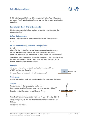
Science and Mechatronics Aided Research for Teachers 2003—2005where m is the mass of the object and g is the free-fall acceleration. This value is only anapproximation because the magnitude of g depends on the altitude of the object as well as the latitude ofthe location. However, because the spatial differences in acceleration due to gravity are so small, theapproximation is well justified. The magnitude of the gravitational force exerted on an object is referredto as its weight. See [8] for more details.Normal forceThe normal force is a contact force that acts in the normal direction, i.e., perpendicular to, thecontact surface between two objects. For an object subjected to no forces other than gravity, themagnitude of the normal force is equal to the component of the gravitational force that acts normal to thesurface, but it acts in the opposite direction. See [2, 8] for more details. Figure 1 depicts a free-bodydiagram of a mass, m, lying on a horizontal surface, where the normal force, N , is equal in magnitude tothe gravitational force mg .NmmgFigure 1: Free-body diagram of a mass lying on a horizontal surface2.2. FrictionThere are different forms of frictional forces that occur. When friction acts on an object that is atrest, we refer to the frictional force as static friction. An object that is in motion is subject to kinetic, ordynamic, friction. Friction is a resistive force, one that damps out motion in dynamic systems andprevents movement in static systems. Friction occurs because an object interacts with either the surface itlays upon, the medium it is contained in, or both. Only in a complete vacuum can a system be free offriction.Static frictionWhen you want to push a heavy object, static friction is the force that you must overcome inorder to get it moving. The magnitude of the static frictional force, f s , satisfiesfs µs Nwhere µ s is the coefficient of static friction, a dimensionless constant that depends on the object and thesurface it is laying upon. From this equation it is clear that the maximum force of staticfriction, f s ,max , that can be exerted on an object by a surface isThe National Science FoundationDivision of Engineering Education & Centers
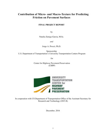
Science and Mechatronics Aided Research for Teachers 2003—2005f s ,max µ s N .Once the applied force exceeds this threshold the object will begin to move. A common example of astatic friction force is that of a stationary mass on an incline. Figure 2 depicts the free-body diagram ofthis case.yfsxNmgθFigure 2: Free-body diagram of a mass on an inclineIf the angle at which the mass begins to slide is known, we can determine µ s by decomposing the forcesinto the Cartesian coordinates, x, y , as given in Figure 2. Since we are interested in the instant at whichmovement begins, we are dealing with an object in equilibrium. Thus, the resultant force in both the xand y directions must be zero. Analysis of the forces in the x direction yieldsf s mg sin θ .(1)Following a similar procedure for the y direction yieldsN mg cos θ .(2)However, we know that at the instant that the mass begins to movef s f s ,max µ s N .(3)Thus, by substituting (2) into (3) and equating the result with (1) we can solve for µ s as followsf s µ s mg cos θ mg sin θ µ s tan θ .Kinetic frictionOnce the force applied on a mass exceeds f s ,max and the mass begins to move, a kinetic frictionforce, f k , exists. Kinetic friction coefficients are generally less than static friction coefficients, which isthe reason that it is much easier to keep a heavy object in motion than it is to start it in motion [4]. Themagnitude of the kinetic frictional force is given as followsfk µk NThe National Science FoundationDivision of Engineering Education & Centers
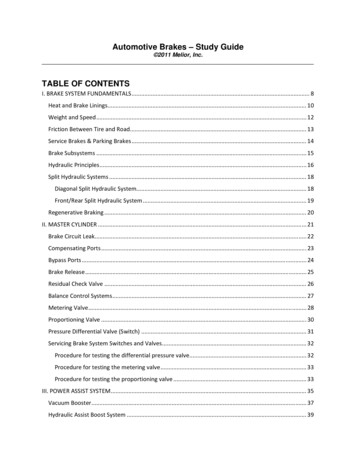
Science and Mechatronics Aided Research for Teachers 2003—2005where µ k is the coefficient of kinetic friction and is approximately constant. Figure 3 is a plot offrictional force versus applied force [1, 8]. The slight fluctuations in the kinetic region of the plot are dueto the slight dependency of µ k on the speed of the object [8].Figure 3: Plot of frictional force versus applied forceTable 1 lists the coefficients of static and kinetic friction for various object/surface combinations[5, 8]. The coefficient of static friction is less than that of kinetic friction for all cases in the table exceptTeflon on Teflon.Table 1: Coefficients of static and kinetic frictionMaterialsSteel on SteelAluminum on SteelCopper on SteelRubber on ConcreteWood on WoodGlass on GlassWaxed wood on Wet snowWaxed wood on Dry snowMetal on Metal (lubricated)Ice on IceTeflon on TeflonSynovial joints in humansCoefficients of StaticFriction ( µ s )Coefficients of KineticFriction ( µ k 70.470.360.80.20.40.10.040.060.030.040.003Rolling frictionRolling friction is a special case of kinetic friction. When we say that a wheel rolls withoutslipping, we are implying that the wheel is subjected to rolling friction. The motion of a wheel underrolling conditions is not affected by kinetic friction. There are no dissipative forces acting on the wheelsubject to rolling friction, under ideal conditions, because the wheel does not slip at the point of contact.As a result, rolling friction does not impede on the motion of the wheel. However, once rolling ceases,kinetic friction is the only frictional force acting on the wheel.The National Science FoundationDivision of Engineering Education & Centers
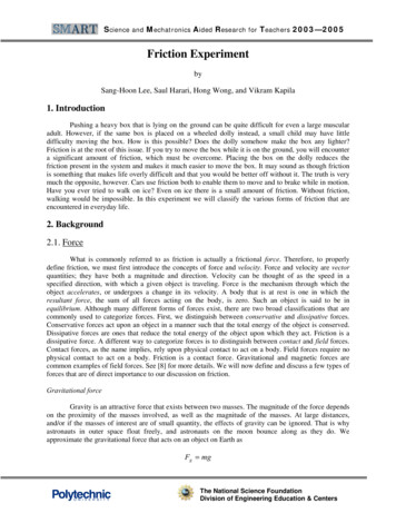
Science and Mechatronics Aided Research for Teachers 2003—2005In non-ideal conditions, rolling friction on a wheel does act as an energy dissipative force due totrace slippage caused by flexing of the wheel. Experimentally, the coefficient of rolling friction betweenthe tire and the road is found to be 0.02-0.06, whereas the coefficient of static friction between the tire andthe road is found to be 0.8. See [2] for more details.3. Equipment listBoard of Education (BOE) with Basic Stamp 2 (BS2)The combination of the BS2 embedded within the BOE will serve as the microcontroller thatmonitors the experiments that you are about to do. The BS2 is a 24 pin Dual Inline Package (DIP)integrated circuit (IC). It is based on Microchip Inc.’s PIC 16C57 microcontroller. The BS2 is powered bya 6-14V direct current (VDC) power supply. An onboard voltage regulator provides a steady 5VDCoutput to the BS2. The BS2 comes with ROM, 2KB Electronically Erasable Programmable ROM(EEPROM), and a small amount of RAM. The BS2 is programmed in PBasic language, the instruction setthat is stored in the BS2 ROM. The user defined program is downloaded into the EEPROM from a PC tothe BOE using a DB-9 serial cable. The excess EEPROM can be used for long term data storage. TheBS2 has 16 general purpose digital input/output (I/O) pins that are user defined. The high position on adigital I/O pin refers to a 5VDC and a low position on a digital I/O pin refers to a 0VDC (groundpotential). Each pin can source (supply) a maximum current of 20mA and sink (draw) a maximum currentof 25mA. The 16 I/O pins on the BS2 at any given time can source/sink a maximum of 40mA/50mA. Ifusing an external 5VDC voltage regulator, these limits apply to each group of 8 pins, P0-P7 and P8-P15.Exceeding these current source/sink limits or establishing a voltage on a pin greater than 5VDC willdamage the BS2. See [6, 7] for more details.A limitation that often arises when using the BS2 is the lack of support for floating pointvariables. Utilizing floating point operations like division in the absence of floating point variables maylead to mathematical errors due to truncation. The largest variable or constant that can be stored on theBS2 is of word size (16 bits), which has a numerical range of 0-65,535 in decimal notation.A BOE and BS2 are depicted in Figure 4 [3]. The BS2 is placed, in the same orientation asshown, in the IC socket in the lower left corner of the BOE.Figure 4: Parallax Board of Education with a Basic Stamp 2 at rightStatic friction experiment test bedThe static friction coefficient test bed will be used to experimentally determine the coefficient ofstatic friction between various surfaces. It consists of a horizontal base and a plate that can be rotatedfrom a level plane that corresponds to θ 0 , and where the vertical position corresponds to θ 90 .The test bed relies upon µ s tan θ , an equation that we have previously derived. The plate, which isThe National Science FoundationDivision of Engineering Education & Centers
Science and Mechatronics Aided Research for Teachers 2003—2005connected to the base through a hinge, is rotated by a DC motor. The DC motor is driven by a regulated12 VDC external power supply. An H-Bridge is used to control the rotational direction of the DC motor.An InfraRed (IR) transmitter and receiver pair is used to detect movement of the mass. The pair has beenmounted on the opposing sidewalls of the plate facing each other. The IR transmitter continuously sendsan infrared pulse towards the receiver. When the mass starts to slide, it interrupts the infrared beam. Toensure accuracy, the experiment must be conducted so that the first instant of the mass’s movement isdetected. To achieve this accuracy, a stopper has been placed at the free end of the plate such that byplacing the mass snug against it the IR beam will be tripped the instant the mass begins to slide. Once theIR receiver has been tripped, the BS2 shuts the motor down. The angle at which the mass begins to slideis measured by a rotary potentiometer connected to the hinge on which the plate turns. A constant 5VDCvoltage is applied across the full resistance of the potentiometer. The wiper rotates along with the plate,and the voltage between the wiper and one end of the potentiometer is measured. Since the BS2 is adigital device and the quantity being measured is an analog voltage, an Analog to Digital Converter(ADC) IC is utilized. The quantization number, Q, of an ADC depends on the number of bits the ADChas and on the span (range of values) that is being digitized. Q for an n -bit ADC is given byQ Vspan2nwhere Vspan is the voltage span to be digitized. This test bed uses an ADC0831 from NationalSemiconductor, an 8-bit, successive approximation converter that is easily interfaced with the BS2 usingthe PBasic shiftin command. See [6, 7] for more details. As an 8-bit device it can convert an analog signalinto 256 discrete levels. To maximize the sensitivity of the ADC the offset and span voltages wereprovided to the ADC by adjusting two potentiometers to provide the proper voltages. A stopper has beeninstalled at the foot of the plate to prevent the mass from falling down. Circuit schematics for the staticfriction coefficient can be found in Appendix A.Figure 5 is an overhead view of the test bed. The DC motor can be seen in the lower left handcorner of the figure. The potentiometer can be seen in the upper left hand corner. The stopper thatprevents the mass from falling of the plate can be seen on the left hand side of the figure. The electricalcircuitry used by the test bed can be seen on the right hand side of the figure.PotentiometerADC with spanand offsetCircuitryStopperH-BridgeDC motorFigure 5: Overhead view of the static friction coefficient test bedThe National Science FoundationDivision of Engineering Education & Centers
Science and Mechatronics Aided Research for Teachers 2003—2005Figure 6 is a close up view of the test bed. In the upper left hand corner of the figure the IRreceiver is visible. In the lower right hand corner of the figure the IR transmitter is visible. The stopperused to mark the starting position of the mass can be seen behind the mass.StopperIR receiverIR transmitterFigure 6: A view of the static friction coefficient experiment4. Experimental procedure4.1. Static friction experimentFigure 7 is an illustrative diagram depicting the functionality of this experiment. A mass is placedon the plate, which is then rotated until the mass begins to slide down the inclination. An IR receiverdetects the first instant of the mass’s motion.IR transmitterIR receiverθFigure 7: Static friction coefficient experimentGoal:1. Experimentally verify that the coefficient of static friction for various surfaces.Static friction experiment procedure1. Connect the BS2 to the test bed with the DB-9 adapter located on the test bed, and to a computerwith another DB-9 serial cable.2. Connect the BS2 to a 9VDC power source, either a power adapter or battery can be used.3. Download the StaticFriction.bs2 file to the BS2.4. At the prompt place the mass on the test bed, lining it up properly.5. The BS2 will then rotate the plate through an arc (0 to 90 ) until the IR detector is tripped.6. The BS2 will calculate µ s from the angle at which the IR detector was tripped.7. To continue with this experiment follow the prompts regarding restarting the experiment.The National Science FoundationDivision of Engineering Education & Centers
Science and Mechatronics Aided Research for Teachers 2003—2005DiscussionWhich material has the highest coefficient of static friction? Does this agree with your intuition?What do you think determines the coefficient of static friction? Surface area? Contact area? See [2, 4, 8]for more details.Once the mass begins to slide does it move smoothly, or does it undergo stop and go motion?What possible explanation for the motion can you think of?5. Suggested Project1) Kinetic and static friction coefficient detector: Devise a means of measuring the coefficient ofkinetic friction. It may be possible to modify the static coefficient experiment to accomplish thisproject.6. References[1] Online: http://www.cord.edu/dept/physics/p128/lecture99 12.html, web site of the PhysicsDepartment at Concordia University containing physics lectures.[2] Online: tml, educational web site for physics, math,chemistry, mechanics, and other natural sciences, by Carl R. Nave.[3] Online: http://www.parallax.com, web site of Parallax, Inc. manufacturer and distributor of BasicStamp microcontrollers containing technical specifications and user manuals.[4] Online: http://www.physicseq.com/force/frictionhelp.html, web site of PhysicEq.com containinghigh school level physics tutorials, by Stephen Embree.[5] Online: ents.cfm, web site of Physlink.comcontaining coefficients of static and kinetic friction.[6] Online: http://www.stampsinclass.com, web site of Stamps in Class containing educational resourcesfor Basic Stamp microcontrollers.[7] V. Kapila, Course Notes for Mechatronics ME 3484, Polytechnic University, Brooklyn, NY, (2003).[8] R.A. Serway and R.J. Beichner, Physics for Scientists and Engineers. Saunders College Publishing,Orlando, FL, 5th Ed., (2000).The National Science FoundationDivision of Engineering Education & Centers
Science and Mechatronics Aided Research for Teachers 2003—2005Appendix A: Circuit schematicsFigure A1: Circuit schematic of the ADC used to digitize the angle of inclinationFigure A2: Circuit schematic of the IR transmitter/receiver pair used to detect motionThe National Science FoundationDivision of Engineering Education & Centers
Science and Mechatronics Aided Research for Teachers 2003—2005Figure A3: Circuit schematic of an H-Bridge using BJT transistorsThe National Science FoundationDivision of Engineering Education & Centers
the tire and the road is found to be 0.02-0.06, whereas the coefficient of static friction between the tire and the road is found to be 0.8. See [2] for more details. 3. Equipment list Board of Education (BOE) with Basic Stamp 2 (BS2) The combination of the BS2 embedded within the BOE will serve as the microcontroller that