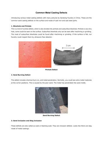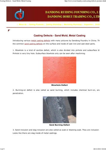
Transcription
IJRET: International Journal of Research in Engineering and TechnologyeISSN: 2319-1163 pISSN: 2321-7308SAND CASTING: CONVENTIONAL AND RAPID PROTOTYPINGMANUFACTURING APPROACHESSagar M Baligidad1, N Krishnamurthy2, N Narendra3, Ajay Srinivasan N41Assistant Professor, Mechanical Engineering Department, CMR Institute of Technology, Bangalore, India2Professor, Mechanical Engineering Department, CMR Institute of Technology, Bangalore, India3Assistant Professor, Mechanical Engineering Department, CMR Institute of Technology, Bangalore, India4Research Scholar, Mechanical Engineering Department, CMR Institute of Technology, Bangalore, IndiaAbstractSand casting provides an economic method for mass production of complex and intricate features of metal parts. Manufacturingof moulds to cast small and medium type products involve relatively long lead time and high tooling costs. The application ofRapid Prototyping (RP) technologies to fabricate complex sacrificial patterns can result significant reduction in the cost and leadtime associated with the manufacture of single, small or medium quantity productions. Previously this technology was used todevelop a model of products. The current research work involves fabrication of pattern using Rapid Prototyping technique andsame is used to produce metal castings. A comparison study has been done in the sense of lead time, dimensional accuracy,surface quality and cost investment of patterns and castings produced using RP technique and conventional method (usingwooden pattern). It was observed that the patterns produced by the RP Technique have higher dimensional accuracy, goodsurface finish and nominal cost investment. Also the castings produced by this technique have dimensions, surface quality similarto that of pattern produced by this technique. It also reduces the manufacturing lead time.Keywords: Sand casting, Rapid prototyping, Rapid tooling, Dimensional accuracy and Surface quality etc -----------------------------------------1. INTRODUCTIONSand casting is one of the oldest metal manufacturingtechniques, it employs wooden pattern to develop mouldcavity by ramming the moulding sand around the pattern.The molten metal is poured in to the mould cavity andallowed for solidification. After the molten metal getssolidified, the mould is broken and the solid casting isremoved [1].Conventional sand casting method requires machine toolsfor the manufacturing of wooden patterns. Tooling costdepends on the complexity of the pattern. It is less forsimple design but for complex design the tooling cost aswell as time required to develop the design will be high.This conventional method is not economical when numberof castings required is small in quantity.Now there is an industrial need for manufacture of intricatecastings, for defense, vintage equipment and medicalprosthetics. Rapid Prototyping (RP) technique is a combinedsystematic approach which utilizes rapid tooling and internettechnologies in manufacturing [2]. It involves automatedfabrication of intricate shapes from Computer AidedDrafting (CAD) data using layer-by-layer principle. Itallows designer to quickly create tangible prototypes of theirdesigns. Development of intricate castings involveschallenges of economic visibility, quick tooling andproduction of defect free castings in the first attempt. Thesechallenges are overcome by employing RP technologywhich develops patterns for sand casting process. RPtechniques can be used to develop complex patterns; also,the tool costs associated with the design and production ofcomplex pattern will be avoided [3]. In conventional castingprocess, each iterative step requires substantial time and costinvestments to modify the metal tooling. By employing RPfabricated pattern to one can reduce the iteration time andcost investment in tooling for single and small quantityproductions.The first use of RP models as a pattern started in the year1989 [4, 5]. There are various types of commerciallyavailable RP techniques used to fabricate patterns, each withunique capabilities. These are Stereo lithography (SLA),Fused Deposition Modeling (FDM), Laminated ObjectManufacturing (LOM), Selective Laser Sintering (SLS),Solid Ground Curing (SGC), Ink-Jet Printing (IJP) [6].The main objective of this work is to produce sand castingsof impeller of a centrifugal compressor using wooden andRP pattern and compare the dimensional accuracy, surfacequality and cost investment of these castings.2. METHODOLOGYThe procedure adopted to build the model in FDM rapidprototyping processes is termed as methodology.Methodology involves various steps to obtain the requiredoutcome. Procedure has a logical sequence between the eachactivity, where the sequence defines the step-by-stepapproach towards the desired goal. Exact sequence of thetask is essential failing which the required goal may not beachieved. The industries/foundries are therefore goingtowards the advanced techniques such as Computer AidedVolume: 03 Special Issue: 11 NCAMESHE - 2014 Jun-2014, Available @ http://www.ijret.org234
IJRET: International Journal of Research in Engineering and TechnologyDesign and Computer Aided Manufacturing (CAD/CAM).In this work, Computer Aided Design is used to generate thecomponent part where as Rapid Prototyping is used forbuilding pattern of impeller. The following procedure isapplied in the production of RP pattern of impeller.eISSN: 2319-1163 pISSN: 2321-7308pattern.ABS material is a thermo setting plastic which givesa good surface finish to the pattern. Most of the RPmachines are fairly autonomous, needing little humanintervention.2.5 Cleaning and Finishing2.1 CAD Model CreationFirst, the object to be built is modeled using a ComputerAided Design (CAD) software package. Solid modelers,such as Pro/ENGINEER, can develop 3-D objects moreaccurately than wire-frame modelers such as Auto CAD.The designer can use a pre-existing CAD file or may wish tocreate one separate file especially for prototyping purpose.This process is identical for all types of RP build techniques.The CAD and 3-D drawing of the impeller is shown in Fig.2.1and 2.2.In this step, the pattern is removed from the machine andsupports are detached. Patterns are subjected to surfacetreatment processes such as sanding, sealing, and/or paintingto improve its appearance and durability. The actual patternof the impeller is shown in Fig.2.6.2.2 Conversion to STL FormatThe various CAD packages use different algorithms torepresent solid objects. To establish consistency, the STL(stereo lithography, the first RP technique) format has beenadopted as the standard of the rapid prototyping industry.This format represents a three-dimensional surface as anassembly of planar triangles, "like the facets of a cut jewel."The file contains the coordinates of the vertices and thedirection of the outward normal of each triangle. BecauseSTL files use planar elements, they cannot represent curvedsurfaces exactly. Curvatures can be improved by increasingthe number of triangles but it will increase the file sizewhich requires more time to pre-process and build.Therefore the designer must balance accuracy withmanageability to produce a useful STL file. Fig. 2.3 showsthe conversion of CAD file into STL file.Fig -2.1: CAD drawing of benchmark design of impellermodel.2.3 Slice the STL FileIn this step, a pre-processing program prepares the STL fileto be built. Several programs are available, and most ofthem allow the user to adjust the size, location andorientation of the model. Built orientation is important forseveral reasons. Firstly, properties of rapid prototypes varyfrom one coordinate to another. For example, prototypes areusually weaker and less accurate in z (vertical) directionthan in the x-y plane. In addition, part orientation partiallydetermines the amount of time required to build the model.Placing the shortest dimension in the z direction reduces thenumber of layers, thereby shortening build time. The preprocessing software slices the STL model into a number oflayers from 0.01 mm to 0.7 mm thick, depending on thebuild technique (Fig.2.4). The program may also generate anauxiliary structure to support the model during theconstuction (Fig. 2.5). Supports are useful for delicatefeatures such as overhangs, internal cavities, and thin-walledsections.Fig -2.2: 3-D model of the impeller2.4 Layer by Layer ConstructionIn this step, the actual impeller pattern is constructed usingRP machine. Acrylonitrile Butadiene Styrene (ABS)polymer is used as a material for the constuction ofFig -2.3: CAD file stored in .STL formatVolume: 03 Special Issue: 11 NCAMESHE - 2014 Jun-2014, Available @ http://www.ijret.org235
IJRET: International Journal of Research in Engineering and TechnologyeISSN: 2319-1163 pISSN: 2321-7308Fig -2.4: Slicing of the impeller modelFig -2.7 Aluminium casting by ABS patternFig -2.5: Generation of support material for impeller modelusing INSIGHT softwareFig -2.8 wooden patternFig -2.6 Actual ABS pattern of the impeller2.6 Casting of Impeller using Wooden and ABSFig -2.9 Aluminium casting by wooden patternPatternsCastings of impeller is prepared using ABS pattern byapplying actual foundry procedure. Aluminium is used as thematerial for cating. The casting of impeller using ABSpattern is shown in Fig. 2.7. Also aluminium impeller castingis produced using wooden pattern by applying actual foundryprocedure. Fig. 2.8 and 2.9 shows the wooden pattern andcasting of impeller.3. COMPARISON OF CASTINGS PRODUCEDBY ABS AND WOODEN PATTERNS3.1. Dimensional AccuracySome of the critical sections (Fig.2.1. indicated by numbers1, 2, 3, 4, 5, 6, 7) are selected to examine the dimensionalvariations of ABS and wooden pattern castings. Dimensionaldistribution charts are plotted based on the measured valuesVolume: 03 Special Issue: 11 NCAMESHE - 2014 Jun-2014, Available @ http://www.ijret.org236
IJRET: International Journal of Research in Engineering and TechnologyeISSN: 2319-1163 pISSN: 2321-7308of wooden pattern and its castings as shown in Fig. 3.1 a andb. From the graphs, it is seen that 80% of dimensionaldeviations of the wooden pattern falls within 0.3 mm andthe average dimensional deviation between ABS pattern andwooden pattern is approximately 0.025 mm. For aluminumcasting 80% of dimensional deviation falls within 0.3 mmand average dimensional deviation is 0.051 mm. There is anegligible dimensional deviation in both the wooden patternand its casting and that can be covered by considering majorcompensating factors. The shrinkage rate of aluminumcasting is approximately 1.45%.Microstructure of a wooden pattern was built more denselyand extremely brittle as compared to ABS pattern. There wasno porous structure and no sealing or coating was needed onthe part surface. The average surface roughness of woodenpattern and the aluminum casting were measured as 0.61 and6.7 μm.Fig -3.1 Dimensional deviation distribution chart for a)wooden pattern b) aluminium castingThe dimensions of hollow ABS pattern and its casting weremeasured and recorded. Dimensional distribution charts areplotted based on the above data as shown in Fig. 3.2 a and b.From Fig. 3.2, it is observed that 80% of dimensionaldeviations of the ABS pattern fall within 0.3 mmDimensional deviation between CAD model and woodenpattern is approximately 0.025mm. For aluminum casting80% of dimensional deviation falls within 0.3 mm andaverage dimensional deviation is 0.045 mm. There is anegligible dimensional deviation of both the wooden patternand aluminum casting and that can be covered byconsidering major compensating factors. The shrinkage rateof aluminum casting is approximately 1.38%.Microstructure of ABS pattern is dense and not extremelybrittle as compared to wooden pattern. There is no porousstructure. It has a good surface finish. The average surfaceroughness of ABS pattern and its casting is about 0.71 and4.7μm respectively. The casting obtained from the ABSpattern has no major defects and was cast exactly to therequired dimensions.Fig -3.2 Dimensional deviation distribution chart of a)ABS pattern b) aluminium casting3.2. Cost and Manufacturing Lead TimeBoth manufacturing lead-time and cost investment studieswere carried out on conventional and RP methods. The dataobtained is shown in table 3.1 and 3.2.The key limitation of employing wooden master pattern overFDM-fabricated patterns includes the long build time for theprocess to manufacture a part. For the manufacture ofimpeller model, the wooden master pattern took 22 hourswhile the FDM process took only 6.25 hours. The costinvolved for manufacturing the wooden master pattern isabout Rs 300 and for FDM pattern is about Rs 600.Volume: 03 Special Issue: 11 NCAMESHE - 2014 Jun-2014, Available @ http://www.ijret.org237
IJRET: International Journal of Research in Engineering and TechnologyMaximum replicate can be cast by using FDM pattern isaround 130-150 and by using wooden pattern 40-60components can cast.Table -3.1 Comparison of MLT of castingsParticularsManufacturing Lead Time (hr)RP Method4Conventional Method42.2518Total time6.2522Man power(Nos)12CAD modelHollowpatternABSTable -3.2 Comparison of Cost of castingsParticularsCostConventional MethodFDM patternRPMethod600Max. replicate130-15040-60Total cost6003003004. CONCLUSIONSFollowing conclusions can be made from this research work1. The casting obtained from the RP method has moredimensional accuracy and high surface quality2. The pattern made by ABS material can be used toproduce more number of castings.3. RP method involves less Manufacturing Lead timeand nominal investment to produce patterns.4. Patterns with complex shapes can be built easilyREFERENCES[1]. Kalpakjian S Manufacturing processes for engineeringmaterials, 2nd edn. Addison-Wesley, New York, 1991.[2]. Lee CW, Chua CK, Cheah CM, Tan LH, Feng C Rapidinvestment casting: direct & indirect approaches via fuseddeposition modeling. Int J Adv Manuf Technol 23(1–2),2004, pp 93–101[3]. Chua CK, Leong KF, Lim CS Rapid prototyping:principles & applications. World Scientific, Singapore, 2003[4]. Greenbaum PY, Khan S, Direct investment casting ofrapid prototype parts: practical commercial experience.Proceedings of 2nd European Conference on RapidPrototyping, Nottingham, UK, 15–16 July 1993, pp 77–93,[5]. Greenbaum PY, Pearson R, Khan S, Direct investmentcasting of RP parts: practical commercial experience.Proceedings of 4th International Conference on RapidPrototyping, Dayton, OH, 14–17 June 1993 pp 43–50,[6]. Dickens M, Stangroom R, Greul M, Conversion of RPmodels to investment castings. Rapid Prototyping J 1(4),1995, pp 4–11.eISSN: 2319-1163 pISSN: 2321-7308BIOGRAPHIESMr. Sagar M Baligidad is working as anAssistant Professor in MechanicalEngineering Dept. of CMR Institute ofTechnology. Bangalore, Karnataka, India.He was awarded his Master of TechnologyDegree from “Jnana Sangama” VTUBelgaum. He is pursuing his PhD fromVTU, Belgaum. He has 2 years of research and 3 years National conferences. His area of interestRapid prototyping, collaborative manufacturing &Alternative energy.Dr. N Krishnamurthy obtained Ph.D. fromVTU Belgaum. He is currently working asProfessor in Mechanical Engineering Dept.of CMR Institute of TechnologyBangalore, India. He has 1 year industrial,8 years of research and 17 years ofteaching experience. He has more than 8research publications in international journals and more than13 International/National conferences. His area of interestcomposites, thermal barrier coatings, alternative energy andadvanced manufacturing technique.Mr. N Narendra is working as an AssistantProfessor in Mechanical Engineering Dept.of CMR Institute of Technology.Bangalore, Karnataka, India. He wasawarded his Master of Technology Degreefrom MVJ college of Engineering,Bangalore, India. He has 2 years of industrial and 3 years ofteaching experience. His area of interest Rapid prototyping,collaborative manufacturing & alternative energy.Mr. Ajay Srinivasan N is pursuing hisbachelor of Engineering from CMRInstitute of Technology Bangalore, India.His areas of Interest include Rapidprototyping, IC Engine and alternativeenergy.Volume: 03 Special Issue: 11 NCAMESHE - 2014 Jun-2014, Available @ http://www.ijret.org238
surface finish and nominal cost investment. Also the castings produced by this technique have dimensions, surface quality similar to that of pattern produced by this technique. It also reduces the manufacturing lead time. Keywords: Sand casting, Rapid prototyping, Rapid tooling, Dimensional accuracy and Surface quality etc .