Transcription
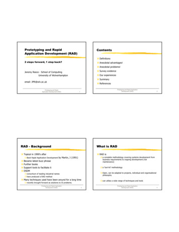
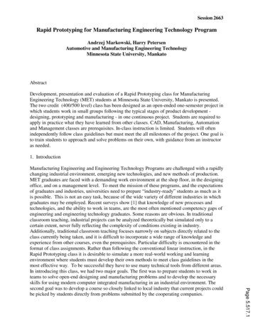
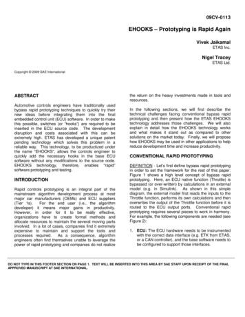
09CV-0113EHOOKS – Prototyping is Rapid AgainVivek JaikamalETAS Inc.Nigel TraceyETAS Ltd.Copyright 2009 SAE InternationalABSTRACTAutomotive controls engineers have traditionally usedbypass rapid prototyping techniques to quickly try theirnew ideas before integrating them into the finalembedded control unit (ECU) software. In order to makethis possible, switches (or “hooks”) are required to beinserted in the ECU source code. The developmentdisruption and costs associated with this can beextremely high. ETAS has developed a unique patentpending technology which solves this problem in areliable way. This technology, to be productized underthe name “EHOOKS”, allows the controls engineer toquickly add the necessary hooks in the base ECUsoftware without any modifications to the source code.EHOOKS technology, therefore, enables “rapid”software prototyping and testing.INTRODUCTIONRapid controls prototyping is an integral part of themainstream algorithm development process at mostmajor car manufacturers (OEMs) and ECU suppliers(Tier 1s).For the end user (i.e., the algorithmdeveloper) it means major gains in productivity.However, in order for it to be really effective,organizations have to create formal methods andallocate resources to maintain the several moving partsinvolved. In a lot of cases, companies find it extremelyexpensive to maintain and support the tools andprocesses required.As a consequence, algorithmengineers often find themselves unable to leverage thepower of rapid prototyping and companies do not realizethe return on the heavy investments made in tools andresources.In the following sections, we will first describe thetechnical challenges facing conventional bypass rapidprototyping and then present how the ETAS EHOOKStechnology addresses those challenges. We will alsoexplain in detail how the EHOOKS technology worksand what makes it stand out as compared to othersolutions on the market today. Finally, we will proposehow EHOOKS may be used in other applications to helpreduce development time and increase productivity.CONVENTIONAL RAPID PROTOTYPINGDEFINITION - Let’s first define bypass rapid prototypingin order to set the framework for the rest of this paper.Figure 1 shows a high level concept of bypass rapidprototyping. Here, an ECU native function (Throttle) isbypassed (or over-written) by calculations in an externalmodel (e.g. in Simulink). As shown in this simplediagram, the external model first reads the inputs to theThrottle function, performs its own calculations and thenoverwrites the output of the Throttle function before it isrouted to the ECU output ports. Conventional rapidprototyping requires several pieces to work in harmony.For example, the following components are needed (seeFigure 2):1. ECU: The ECU hardware needs to be instrumentedwith the correct data interface (e.g. ETK from ETAS,or a CAN controller), and the base software needs tobe configured to support those interfaces.DO NOT TYPE IN THIS FOOTER SECTION ON PAGE 1. TEXT WILL BE INSERTED INTO THIS AREA BY SAE STAFF UPON RECEIPT OF THE FINALAPPROVED MANUSCRIPT AT SAE INTERNATIONAL.
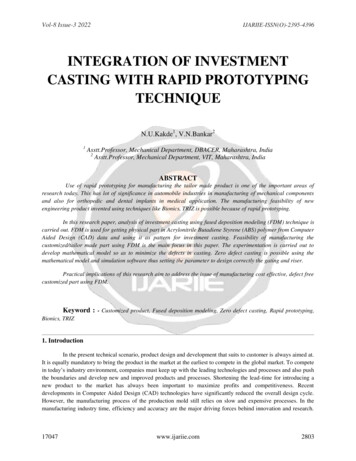
2. Prototyping Hooks: The ECU function or variablethat will be bypassed needs to have a “hook”implemented that allows the software to switchbetween its internal value and that calculated by thebypass function. It also allows the user to controlwhich value is used.to conform to the targeted development process. Afterthis is done, the tools are made available for thealgorithm engineer to use.Figure 1: Schematic of Bypass Rapid PrototypingFigure 2: Typical System Components3. External Processor: Usually the bypass function isexecuted on an external processor that is morepowerful than the ECU’s microprocessor.4. The data interface: The data interface between theECU and the external processor is crucial for thereal-time performance of the bypass system.5. Software Services: Support services in the ECUsoftware are needed to manage the efficienttransport of data to/from the external processor.These services also monitor the health of the datalink, and abort bypass if the link is broken.6. Trigger Mechanism: In order for the bypassfunction to run synchronously with the timer andevent based tasks of the real-time operating system(RTOS) implemented in the ECU, a triggermechanism needs to be in place. This allows theECU microprocessor to be the master scheduler,and the external processor to be the slave.7. Configuration Tool: The PC application that allowsthe new control algorithms to be mapped to thebypass hooks in the ECU base software, compileand execute the algorithms in the externalprocessor, and manage/control the experiment inreal-time.EXAMPLES OF HOOKS – The usefulness andapplication of hooks (or switches) is determined by theirlocation relative to an ECU function of interest. Forexample, for rapid prototyping, a hook is typically placedafter an internal ECU function calculation is complete(Figure 3). Thus the ECU calculated value is overwrittenby a different value. Bypass rapid prototyping relies onhooks of this type to allow testing of new algorithms.Typically, an ECU tool vendor provides some of thepieces above, while the Tier 1 supplier or OEM providesthe rest. There is an initial integration phase where thesoftware services, hooks, interfaces and tools are testedFigure 3: A Rapid Prototyping HookIf the hook is placed at the input of the ECU function,however, it represents a different application (Figure 4).Test and validation engineers may use hooks of thistype to test the robustness of the ECU function in thepresence of input variability. Design engineers, on the
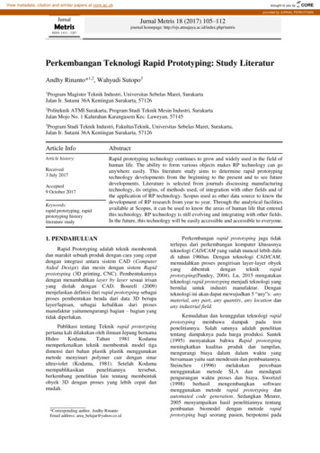
other hand, find it useful to test new sensor designs withexisting ECU software. Figure 4: A Test and Validation HookHooks may also be placed to re-write any ECU variablelocated in RAM with a calibration parameter that may beadjusted during run-time (Figure 5). Such hooks areuseful when you need to fix a certain ECU value in orderto focus on behavior observed downstream or isolateproblems one by one.Calibration and diagnosticengineers find such hooks to be especially useful.Memory information – e.g. ROM and RAM for theaddition of user functions and bypass hooks.Information regarding the ECU software architecture(e.g., the structure of global and local variables,update rate of key variables etc.)ECU variables and functions that may be bypassedby the end user. Software suppliers can use thisfeature to protect certain areas of their software (e.g.key input/output and diagnostic functions) frombeing overwritten unintentionally by the end user.ECU variables and functions that can be utilized bythe bypass functions (e.g., math libraries, internalsensor values etc.)ECU RTOS tasks and function containers that maybe used to execute bypass models.In addition, this phase disables the ECU checksums(which might otherwise cause the ECU to shut down)and adds certain EHOOKS support functions andadministrative calibrations/variables to the basesoftware. Through this process, EHOOKS ensures thatthe subsequent hook installation phase results in arobust and reliable ECU image.HOOK INSTALLATION PHASE – The second tool(called the EHOOKS Hook Insertion Tool) exploits theinformation stored in the A2L file by the Preparation Tooland uses it to configure and install the bypass hooks intothe base HEX file. It does this in several steps: First, the user selects (from the A2L file) whichvariables in the base software will be bypassed, andwith which type of hooks (e.g. constant, calibration,external, internal). EHOOKS also allows a copy ofthe original ECU value to be created for comparisonpurposes. Example dialogs are shown in Figures 6and 7. Both replacement and offset modes ofbypass are supported (Figure 8).Figure 5: Calibration and Diagnostics HooksEHOOKS TECHNOLOGYIn the conventional framework described above, newcontrol algorithms invariably require new software hooksto be placed in the base software. This task is arduous,expensive and causes significant developmentdisruption – taking the rapid out of rapid prototyping!EHOOKS enables the end user to place all necessaryhooks without the hassle of making changes to the basesoftware. EHOOKS does this in the following way.PREPARATION PHASE – An essential element ofEHOOKS technology is the Preparation Tool. Thissoftware tool allows the initial one-time preparation ofthe ECU base software (e.g., by the Tier 1 supplier). Italso captures and stores the following information insidean encrypted block in the ASAM-MCD-2MC (or A2L) file:Figure 6: Selection dialog for Installing Hooks The Installation Tool then locates the writeinstructions to these variables in the base HEX file.As part of EHOOKS technology, ETAS has
developed an instruction set simulator (ISS) thatallows these write instructions to be correctly locatedeven in the presence of complex addresscalculations (Figure 9).Once the writes are located, the Hook Insertion Toolpatches those locations with jump instructions toreserved memory areas where special hook-code isinserted (Figure 9).The hook control parameters are also added to thecalibration memory of the ECU (e.g. the Enableparameter for each hook in Figure 8).User provided code for bypass functions is compiledby EHOOKS, which then generates the necessarylink script to ensure the code (and its data) arelocated within the ECU memory sections reservedfor use by EHOOKS as described in the encryptedsection of the A2L file.During each build EHOOKS checks to ensure theavailable ECU resources reserved for EHOOKS useare sufficient for the specific configuration. If not,the build is halted with an error.The A2L file is updated with all the necessary hookcontrol parametersFigure 8: Bypass Modes supported by EHOOKSThe user can now rewrite the ECU memory with the newHEX file using standard flashing and/or debugging toolsor calibration tools that support flashing (e.g. ETASINCA software). The new A2L file may be used bystandard calibration tools for accessing and controllingthe operation of the hooks during run-time.Figure 9: The original and patched ECU imagesTYPES OF HOOKS – With EHOOKS, several types ofhooks may be inserted in the original ECU softwareimage, enabling several different use cases.1. Constant Value Hooks (Figure 10) are useful whenyou need to fix an ECU RAM variable to a constantvalue (e.g. to simulate a faulty sensor). Once fixed,the value cannot be changed during run-time. It hasto be changed by the EHOOKS Installation Tool anda new software image has to be flashed to the ECU.Figure 7: Selection of Hook Properties
additional ECU resources) to on-target and externalrapid prototyping.Figure 10: A Constant Value Hook2. Calibration Hooks (Figure 11) are useful when youneed to control the value of an ECU RAM variableduring run-time using a standard calibration tool(e.g., INCA from ETAS). The calibration parameteris automatically added to the A2L file by theEHOOKS Installation Tool.Figure 13: External Bypass HooksFigure 11: A Calibration Value Hook3. Internal Bypass Hooks (Figure 12) allow an ECURAM variable to be overwritten by an algorithmrunning directly on the ECU. This methodology,commonly known as on-target prototyping, is veryuseful when the ECU has spare resources (ROM,RAM, task-time) available to run new algorithms.The technology leverages proprietary ECU internalinformation encrypted and stored in the A2L file by theTier 1 supplier. This allows EHOOKS to not only reliablydetect all write instances of a RAM variable, but alsoinstitute run-time safety detection mechanisms that alertthe user to potential data inconsistencies during runtime. In addition, the hook code inserted by EHOOKSincludes the code from the original ECU software suchthat, if the hook is disabled, the original ECU softwarefunctionality is restored.ADVANCED APPLICATIONSIn addition to the use cases described above, EHOOKStechnology may be applied to solve a myriad ofadvanced problems related to software developmentand validation. Some of these are described below.Figure 12: Internal Bypass Hooks1. Disabling an ECU process: The order of executionof processes inside an ECU task is pre-defined andnormally cannot be altered by the user.4. External Bypass Hooks (Figure 13) allow traditionalbypass rapid prototyping using an externalprocessor. Bypass algorithms may be developed inmodel-based tools such as ASCET from ETAS orSimulink from The Mathworks, or directly in C-code.EHOOKS only configures the hooks in the ECUimage to accept values written by an external target,independent of which external target or modelinglanguage is actually used.EHOOKS, therefore, provides a completely scalablesolution for a wide variety of applications – starting fromsimple calibration use cases (that require minimumFigure 14: Disabling an ECU process
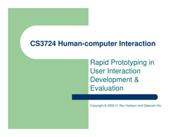
The encrypted A2L block created by the EHOOKSPreparation Tool allows the Tier 1 supplier tosecurely provide the process list to the EHOOKSInstallation Tool, which then allows the user to selectand control the execution of specific processes(Figure 14). This feature is useful, for example,when: An entire ECU function has to be bypassed.By disabling the whole process, significantCPU resources can be freed-up for a newalgorithm, or An errant ECU process is preventingdownstream processes from functioningproperly, or is paralyzing the ECU.2. Scheduling of on-target algorithms:EHOOKSprovides the flexibility to leverage existing ECUresources in the best way possible. One way to dothis is to allow user code for on-target algorithms torun within a dedicated process created solely for thatpurpose. These processes are known as “bypasscontainers” (Figure 15). The actual software hookmay reside in a different (e.g. faster) process, butdue to bandwidth limitations it may be not bepossible to execute the new algorithm in the sametask. In many cases, it is still be acceptable to runthe new algorithm in a slower task in order to checkits validity. The EHOOKS Hook Insertion Tool(optionally) allows the user to pick the bypasscontainer from an available list of processes, andassign the algorithm to it.cam, wheel speeds). The sensor signals areidentical to those available on a real vehicle and arepassed to the ECU via the electrical harness. Inreturn, the actuator signals computed by the ECUsoftware are sent back over the harness to the HiLsystem, where electrical or simulated loads are usedto emulate the conditions found on the vehicle. Thisprocess requires extensive signal conditioning onthe HiL system in order to convert physical values(e.g. temp in deg F, speed in m/s) to electricalvalues (e.g. voltage) and vice-versa.Figure 16: A conventional HiL system setupFigure 15: Bypass Container Process3. Function in the Loop (FiL): In a traditional hardwarein-the-loop (HiL) setup (Figure 16), the ECU isconnected via an electrical harness to a HiL systemthat runs a vehicle system model in real-time andgenerates the necessary sensor signals (e.g., crank,Figure 17: A Function-in-the-Loop System
Although HiL systems come close to simulating theenvironment of an ECU, there are significant costsinvolved in building the signal conditioning hardwarenecessary for proper operation. In the recent past,the FiL methodology has emerged as a way toovercome these challenges of HiL and reap some ofthe same benefits.With FiL (Figure 17), theexpensive signal conditioning and load hardware isavoided. The plant model running on a real-time PC(e.g. the ETAS LABCAR-RTPC) generates sensorsignals that are copied directly to the ECU memory.Similarly, the actuator commands are read directlyfrom the ECU memory and connected to back to theplant model. This direct exchange of softwaresignals is made possible via a memory emulatorprobe (e.g. the ETAS ETK device) mounted on theECU. Since the electrical interfaces of the ECU areidle, it is necessary to disable diagnostic functions inthe ECU software for FiL to work.CONCLUSIONEHOOKS technology is used to install the necessarysoftware hooks for FiL – e.g., to overwrite an ECUmemory location that is normally used to store asensor value calculated by the ECU.We wish to acknowledge the tireless efforts andinnovative spirit of the entire EHOOKS development andproduct management team at ETAS. In addition, thanksgo to several lead customers who provided invaluableinput and feedback to help ETAS refine the technology.CASE STUDIESAt the time of writing, ETAS is in the final stages ofreleasing the EHOOKS product to the market. However,the technology has already been proven and refinedthrough select lead customer projects over the lasteighteen months. Some key examples of customerprojects are presented below. In Asia, a major OEM is using EHOOKS foraccelerating the development of new ECU functionsvia traditional rapid prototyping. They are now ableto avoid the cost (typically 10k - 30k) of each newsoftware change request for new hooks charged bytheir Tier 1 supplier. They are also able to reducethe number of ECU software releases requiredbefore start of production by about 50%.In Europe, a major OEM is reporting that by usingEHOOKS they are able to create a new softwareversion in about 5 minutes, when it previously tookthem anywhere from one to eight weeks.In Europe, another major OEM’s Tier1 supplier isunable to manually add hooks to the softwarebecause they don’t have access to certain sectionsof the code. In this situation, the only option for theOEM is to use EHOOKS to add the necessarybypass hooks.A FiL system developed by ETAS jointly with aleading European Tier 1 supplier is in use forsoftware development, system integration andtesting.In this paper, we have presented a new patent-pendingtechnology from ETAS that inserts software hooks andcode into an existing ECU software image without theneed for the source code. This technology allows thesoftware vendor (Tier 1) to securely share proprietaryECU architecture and implementation details (necessaryto make EHOOKS flexible and robust), without exposingtheir core intellectual property to the OEMs. Using thistechnology, controls engineers can once again “rapidly”develop and test new strategies either directly on theECU (if there is enough memory and processorbandwidth available) or on an external rapid prototypingsystem (such as the ETAS ES910) without incurring thecost and delays associated with traditional softwarehooks.ACKNOWLEDGMENTSREFERENCES1. Gebhard, M.; Lauff, U.; Schnellbacher, K.: Operationam offenen Herzen – Entwicklung und Test vonSteuergerätefunktionen mit der Bypass-Methode,Elektronik Automotive 2008, Issue 6, Pg. 34-39.2. Dubitzky, W.; Eismann, W; Schinagl, J.:Einsatzmöglichkeiten der Bypass-Methode fürEntwicklung und Test von Steuergerätefunktionen,Electronik Automotive 2008, Issue 8, Pg. 52-56.3. Triess, B.; Müller, C; Lauff, U.; Mößner C.:Entwicklung und Applikation von Motor- tstelle. ATZ AutomobiltechnischeZeitschrift 109 (2007), Issue 1, Pg. 32-39.4. INCA, ASCET, LABCAR-RTPC, ETK and otherETAS products: www.etas.com5. ASAM-MCD-2MC, www.asam.netCONTACTVivek Jaikamal is a Marketing Manager for softwareengineering tools at ETAS, Inc. in Ann Arbor, MI. Hecan be reached via email at vivek.jaikamal@etas.comNigel J. Tracey is a Product Manager for ETASembedded software tools based out of York, UK. Hemay be reached via email at nigel.tracey@etas.com
CONVENTIONAL RAPID PROTOTYPING DEFINITION - Let's first define bypass rapid prototyping in order to set the framework for the rest of this paper. Figure 1 shows a high level concept of bypass rapid prototyping. Here, an ECU native function (Throttle) is bypassed (or over-written) by calculations in an external model (e.g. in Simulink).