Transcription
INTRODUCTION TOCOMSOL Multiphysics
Introduction to COMSOL Multiphysics 1998–2019 COMSOLProtected by patents listed on www.comsol.com/patents, and U.S. Patents 7,519,518; 7,596,474; 7,623,991; 8,457,932;8,954,302; 9,098,106; 9,146,652; 9,323,503; 9,372,673; 9,454,625; and 10,019,544. Patents pending.This Documentation and the Programs described herein are furnished under the COMSOL Software LicenseAgreement (www.comsol.com/comsol-license-agreement) and may be used or copied only under the terms of thelicense agreement.COMSOL, the COMSOL logo, COMSOL Multiphysics, COMSOL Desktop, COMSOL Compiler, COMSOL Server,and LiveLink are either registered trademarks or trademarks of COMSOL AB. All other trademarks are the propertyof their respective owners, and COMSOL AB and its subsidiaries and products are not affiliated with, endorsed by,sponsored by, or supported by those trademark owners. For a list of such trademark owners, see www.comsol.com/trademarks.Version: COMSOL 5.5Contact InformationVisit the Contact COMSOL page at www.comsol.com/contact to submit general inquiries,contact Technical Support, or search for an address and phone number. You can also visit theWorldwide Sales Offices page at www.comsol.com/contact/offices for address and contactinformation.If you need to contact Support, an online request form is located at the COMSOL Access page atwww.comsol.com/support/case. Other useful links include: Support Center: www.comsol.com/support Product Download: www.comsol.com/product-download Product Updates: www.comsol.com/support/updates COMSOL Blog: www.comsol.com/blogs Discussion Forum: www.comsol.com/community Events: www.comsol.com/events COMSOL Video Gallery: www.comsol.com/video Support Knowledge Base: www.comsol.com/support/knowledgebasePart number: CM010004
ContentsIntroduction . . . . . . . . . . . . . . . . . . . . . . . . . . . . . . . . . . . . . . . . . . 5COMSOL Desktop . . . . . . . . . . . . . . . . . . . . . . . . . . . . . . . . . . 6Example 1: Structural Analysis of a Wrench. . . . . . . . . . . . . . . 33Model Wizard. . . . . . . . . . . . . . . . . . . . . . . . . . . . . . . . . . . . . . 34Geometry . . . . . . . . . . . . . . . . . . . . . . . . . . . . . . . . . . . . . . . . . 36Materials . . . . . . . . . . . . . . . . . . . . . . . . . . . . . . . . . . . . . . . . . . 39Global Definitions. . . . . . . . . . . . . . . . . . . . . . . . . . . . . . . . . . . 40Physics and Boundary Conditions . . . . . . . . . . . . . . . . . . . . . 42Mesh . . . . . . . . . . . . . . . . . . . . . . . . . . . . . . . . . . . . . . . . . . . . . 46Study . . . . . . . . . . . . . . . . . . . . . . . . . . . . . . . . . . . . . . . . . . . . . 47Results . . . . . . . . . . . . . . . . . . . . . . . . . . . . . . . . . . . . . . . . . . . . 48Convergence Analysis . . . . . . . . . . . . . . . . . . . . . . . . . . . . . . . 51Example 2: The Busbar — A Multiphysics Model . . . . . . . . . . 59Model Wizard. . . . . . . . . . . . . . . . . . . . . . . . . . . . . . . . . . . . . . 61Global Definitions. . . . . . . . . . . . . . . . . . . . . . . . . . . . . . . . . . . 65Auto Completion and Find for Parameters and Variables . 66Geometry . . . . . . . . . . . . . . . . . . . . . . . . . . . . . . . . . . . . . . . . . 68Materials . . . . . . . . . . . . . . . . . . . . . . . . . . . . . . . . . . . . . . . . . . 73Physics and Boundary Conditions . . . . . . . . . . . . . . . . . . . . . 77Mesh . . . . . . . . . . . . . . . . . . . . . . . . . . . . . . . . . . . . . . . . . . . . . 85Study . . . . . . . . . . . . . . . . . . . . . . . . . . . . . . . . . . . . . . . . . . . . . 87Results . . . . . . . . . . . . . . . . . . . . . . . . . . . . . . . . . . . . . . . . . . . . 87 3
Building an Application with the Application Builder. . . . . . 96Advanced Topics . . . . . . . . . . . . . . . . . . . . . . . . . . . . . . . . . . . . 110Parameters, Functions, Variables, and Couplings . . . . . . . . 110Material Properties and Material Libraries. . . . . . . . . . . . . . 114Adding Meshes . . . . . . . . . . . . . . . . . . . . . . . . . . . . . . . . . . . . 116Adding Physics . . . . . . . . . . . . . . . . . . . . . . . . . . . . . . . . . . . . 119Parametric Sweeps. . . . . . . . . . . . . . . . . . . . . . . . . . . . . . . . . 141Parallel Computing. . . . . . . . . . . . . . . . . . . . . . . . . . . . . . . . . 152COMSOL Multiphysics Client-Server . . . . . . . . . . . . . . . . . 156Appendix A — Building a Geometry . . . . . . . . . . . . . . . . . . . 159Appendix B — Keyboard and Mouse Shortcuts . . . . . . . . . . 176Appendix C — Language Elements and Reserved Names . 181Appendix D — File Formats . . . . . . . . . . . . . . . . . . . . . . . . . . 195Appendix E — Connecting with LiveLink Add-Ons . . . . . 2024
IntroductionRead this book if you are new to COMSOL Multiphysics . It provides anoverview of the COMSOL environment with examples that show you how to usethe COMSOL Desktop user interface and the Model Builder. It also provides aquick introduction to creating applications using the Application Builder.If you have not yet installed the software, install it now according to theinstructions at www.comsol.com/product-download.In addition to this book, an extensive documentation set is available afterinstallation. Tutorials can be found throughout the COMSOL website, includingin the Video Gallery at www.comsol.com/videos and on the COMSOL Blog atwww.comsol.com/blogs. 5
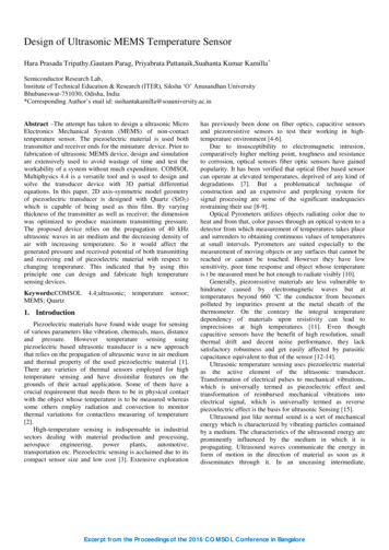
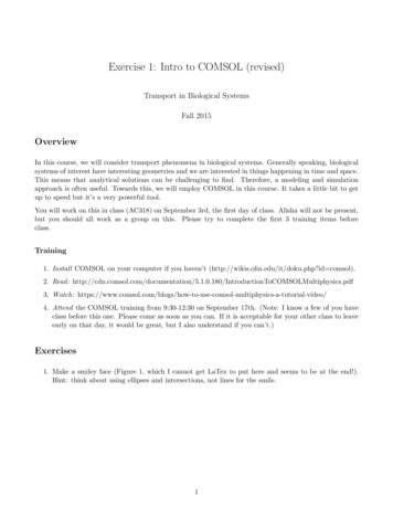
COMSOL Desktop QUICK ACCESS TOOLBAR — Use thesebuttons for access to functionality such as fileopen/save, undo/redo, copy/paste, and delete.RIBBON — The ribbon tabs have buttonsand drop-down lists for controlling allsteps of the modeling process.APPLICATION BUILDER —Click this button to switch tothe Application Builder andstart building an applicationbased on your model.MODEL BUILDERTOOLBARMODEL TREE — The modeltree gives an overview ofthe model and all of thefunctionality and operationsneeded for building and solving6 MODEL BUILDER —SETTINGS WINDOW —The Model Builder windowwith its model tree and theassociated toolbar buttonsgives you an overview of themodel. The modeling processcan be controlled fromcontext-sensitive menusClick any node in the modeltree to see its associatedSettings window displayed nextto the Model Builder.
GRAPHICS WINDOW TOOLBARGRAPHICS WINDOW — The Graphics window presentsinteractive graphics for the Geometry, Mesh, and Results nodes.Operations include rotating, panning, zooming, and selecting.INFORMATION W1NDOWS — The Information windows will display vitalmodel information during the simulation, such as the solution time, solutionprogress, mesh statistics, solver logs, and, when available, results tables. 7
The screenshot on the previous pages is what you will see when you first startmodeling in COMSOL Multiphysics using the Model Builder. The COMSOLDesktop user interface provides a complete and integrated environment forphysics modeling and simulation as well as application design, providing you withthe tools necessary to build a user-friendly interface for your models. You cancustomize the desktop to your own needs. The windows can be resized, moved,docked, and detached. Any changes you make to the layout will be saved whenyou close the session and available again the next time you open COMSOLMultiphysics. As you build your model, additional windows and widgets will beadded. (See page 26 for an example of a more developed desktop.) Among theavailable windows and user interface components are the following:Quick Access ToolbarThe Quick Access Toolbar gives access to functionality such as Open, Save, Undo,Redo, Copy, Paste, and Delete. You can customize its content from the CustomizeQuick Access Toolbar list (the downward-facing arrow to the right of the toolbar).RibbonThe ribbon at the top of the desktop gives access to commands used to completemost modeling tasks. The ribbon is only available in the Windows version of theCOMSOL Desktop environment and is replaced by menus and toolbars in theOS X and Linux versions. Click the Application Builder button to switch from theModel Builder to the Application Builder and start building an application basedon your model.Settings WindowThis is the main window for entering all of the specifications of the model,including the dimensions of the geometry, properties of the materials, boundaryconditions and initial conditions, and any other information that the solver will8
need to carry out the simulation. The picture below shows the Settings window forthe Geometry node.Plot WindowsThese are the windows for graphical output. In addition to the Graphics window,Plot windows are used for visualizing results. Several Plot windows can be used toshow multiple results simultaneously. A special case is the Convergence Plotwindow, an automatically generated Plot window that displays a graphicalindication of the convergence of the solution process while a model is running.Information WindowsThese are the windows for nongraphical information. They include: Messages: Various information about the current COMSOL Multiphysicssession is displayed in this window. Progress: Progress information from the solver in addition to stop buttons. Log: Information from the solver, such as the number of degrees of freedom,solution time, and solver iteration data. Table: Numerical data in table format as defined in the Results node. External Process: Provides a control panel for cluster, cloud, and batch jobs. 9
Other WindowsThe Windows drop-down list in the Home tab of the ribbon gives you access to allCOMSOL Desktop windows. On OS X and Linux , you will find this in theWindows menu. In addition to the windows described earlier you can access thefollowing windows: Add Physics and Add Multiphysics: Expand the physics interfaces in a model. Add Study: Change the type of study. Add Material from Library and the Material Browser: Access the materialproperty libraries. Application Libraries: Choose among the collections of MPH-files containingtutorial models and runnable applications with accompanying documentation. Part Libraries: Load one of the predefined parameterized geometry models. Selection List: Show a list of geometry objects, domains, boundaries, edges,and points that are currently available for selection. Properties: View model tree node properties. Debug Log: Display debug information for methods. Recovery Files: View recovery files. Comparison Results: Compare the Model Builder and Application Buildersettings of two MPH files.Progress Bar with Cancel ButtonThe Progress Bar with a button for canceling the current computation, if any, islocated in the lower right-hand corner of the COMSOL Desktop interface.Dynamic HelpThe Help window provides context-dependent help texts about windows andmodel tree nodes. If you have the Help window open in your desktop (by typingF1, for example), you will get dynamic help (in English only) when you click anode or a window. From the Help window, you can search for other topics, suchas menu items.T h e M o d e l B u i l d e r a n d t h e A p p l i c a t i o n B u il d e rThe two main components of the COMSOL Desktop environment are the ModelBuilder and the Application Builder.The Model Builder is the tool where you define the model and its components,such as how to solve it, the analysis of results, and creating reports. You do that by10
building a model tree. The model tree reflects the underlying data structure, themodel object, which stores the state of the model including settings for geometry,mesh, physics, boundary conditions, studies, solvers, postprocessing, andvisualizations.The Application Builder allows you to quickly create an application with aspecialized user interface that is easy to use. An application is typically based on amodel created with the Model Builder. The Application Builder provides twoimportant tools for creating applications: The Form editor and the Method editor.In addition, an application can have a menu bar or a ribbon. The Form editorincludes drag-and-drop capabilities to easily access and include user interfacecomponents, such as input fields, graphics windows, and buttons. The Methodeditor is a programming environment that, for example, allows you to modify themodel represented by the model object data structure. You can also use theMethod editor to add user interface logic and auxiliary functionality to anapplication. The Java programming language is used to write code in the Methodeditor, which means that all Java syntax and Java libraries can be used.In the Method editor, program code is stored in methods. A method is anothername for what is known in other programming languages as a subroutine,function, or procedure. Methods can be used to modify the model object datastructure in the Model Builder and the Application Builder. A method can be usedboth for modifying the model object of the current session and for modifying themodel object in a running application.This book, Introduction to COMSOL Multiphysics, gives a detailed introductionto using the Model Builder and a quick introduction to the Application Builder.For detailed information on how to use the Application Builder, including theForm editor and Method editor, see Introduction to Application Builder.Applications, COMSOL Server, and COMSOL CompilerThe Application Builder is included in the Windows version of COMSOLMultiphysics. With a COMSOL Multiphysics license, applications can be run fromthe COMSOL Desktop environment. Although applications cannot be built withthe macOS or Linux versions of the software, applications can still be run withCOMSOL Multiphysics on those platforms.With a COMSOL Server license, applications can be run in major web browserson a variety of operating systems and hardware platforms. In addition, you can runapplications by connecting to COMSOL Server with an easy-to-install COMSOLClient for Windows . 11
The COMSOL Client for Windows allows a user to run applications that requirea LiveLink product for CAD (this functionality is not available when runningapplications with a web browser).Running applications in a web browser does not require any installation and noweb browser plug-ins are needed. Running an application in a web browsersupports interactive graphics in 1D, 2D, and 3D. In a web browser, graphicsrendering in 3D are based on WebGL technology, which comes included withall major web browsers.To create an application based on your model, clickthe Application Builder button, accessible from theHome tab in the ribbon.By using the COMSOL Compiler product you cancompile your application (MPH-file) to anexecutable file for Windows , Linux , andmacOS. You can freely distribute the executableand it can be run without any license file.For more information on creating COMSOL applications, refer to the section“Building an Application with the Application Builder” on page 96 and the bookIntroduction to Application Builder.12
PreferencesPreferences are settings that affect the modeling environment. Most are persistentbetween modeling sessions, but some are saved with the model. You access thepreferences from the File menu by selecting Preferences.In the Preferences window, you can change settings such as graphics rendering, thenumber of displayed digits for results, the maximum number of CPU cores usedfor computations, or paths to user-defined application libraries. Take a moment tobrowse your current settings to familiarize yourself with the different options.There are three graphics rendering options available: OpenGL , DirectX , andSoftware Rendering. The DirectX option is not available in macOS or Linux , butis available in Windows if you choose to install the DirectX runtime librariesduring installation. If your computer does not have a dedicated graphics card, youmay have to switch to Software Rendering for slower but fully functional graphics.A list of recommended graphics cards can be found at:www.comsol.com/system-requirements 13
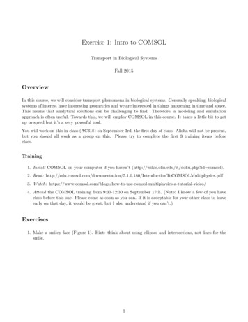
Creating a New ModelYou can set up a model guided by the Model Wizard or start from a Blank Model asshown in the figure below.C REATINGAM ODEL G UIDEDBY THEM ODEL W IZARDThe Model Wizard will guide you in setting up the space dimension, physics, andstudy type in a few steps:1 Start by selecting the space dimension for your model component: 3D, 2DAxisymmetric, 2D, 1D Axisymmetric, or 0D.2 Now, add one or more physics interfaces. These are organized in a number ofphysics branches in order to make them easy to locate. These branches do notdirectly correspond to products. When products are added to your COMSOL14
Multiphysics installation, one or more branches will be populated withadditional physics interfaces. 15
3 Select the Study type that represents the solver or set of solvers that will be usedfor the computation.Finally, click Done. The desktop is now displayed with the model tree configuredaccording to the choices you made in the Model Wizard.C REATINGAB LANK M ODELThe Blank Model option will open the COMSOL Desktop interface without anyComponent or Study. You can right-click the model tree to add a Component of acertain space dimension, physics interface, or Study.16
T h e R i b b o n a n d Q u i c k A c c e s s T o o l b arThe ribbon tabs in the COMSOL Desktop environment reflect the modelingworkflow and give an overview of the functionality available for each modelingstep, including building simulation applications from your models.The Home tab contains buttons for the most common operations for makingchanges to a model, running simulations, and for building and testingapplications. Examples include changing model parameters for a parameterizedgeometry, reviewing material properties and physics, building the mesh, runninga study, and visualizing the simulation results.There are standard tabs for each of the main steps in the modeling process. Theseare ordered from left to right according to the workflow: Definitions, Geometry,Materials, Physics, Mesh, Study, Results, and Developer.Contextual tabs are shown only if and when they are needed, such as the 3D PlotGroup tab, which is shown when the corresponding plot group is added or whenthe node is selected in the model tree.Modal tabs are used for very specific operations, when other operations in theribbon may become temporarily irrelevant. An example is the Work Plane modaltab. When working with work planes, other tabs are not shown, since they do notpresent relevant operations.T HE R IBBONVS .T HE M ODEL B UILDERThe ribbon gives quick access to available commands and complements the modeltree in the Model Builder window. Most of the functionality accessed from theribbon is also accessible from contextual menus by right-clicking nodes in themodel tree. Certain operations are only available from the ribbon, such as selectingwhich desktop window to display. In the COMSOL Desktop interface for macOSand Linux , this functionality is available from toolbars, which replace the ribbonon these platforms. There are also operations that are only available from themodel tree, such as reordering and disabling nodes. 17
T HE Q UICK A CCESS T OOLBARThe Quick Access Toolbar contains a set of commands that are independent of theribbon tab that is currently displayed. You can customize the Quick Access Toolbarand add most commands available in the File menu, including commands forundoing and redoing recent actions, as well as for copying, pasting, duplicating,and deleting nodes in the model tree. You can also choose to position the QuickAccess Toolbar above or below the ribbon.MAC OS ANDL INUX In the COMSOL Desktop environment for macOS and Linux , the ribbon isreplaced by a set of menus and toolbars.The instructions in this book are based on the Windows version of the COMSOLDesktop environment. However, running COMSOL Multiphysics and theCOMSOL Desktop environment in macOS and Linux is very similar, keeping inmind that the ribbon user interface components can instead be found in thecorresponding menus and toolbars.The Model Builder and the M o del Tr eeUsing the Model Builder, you build a model by starting with the default modeltree, adding nodes, and editing the node settings.All of the nodes in the default model tree are top-level parent nodes. You canright-click on them to see a list of child nodes, or subnodes, that you can addbeneath them. This is the means by which nodes are added to the tree.When you click on a child node, you will see its node settings in the Settingswindow. It is here that you can edit node settings.It is worth noting that if you have the Help window open, which is achieved eitherby selecting Help from the File menu or by pressing the function key F1, then youwill also get dynamic help (in English only) when you click on a node.18
T HE R OOT , G LOBAL D EFINITIONS ,ANDR ESULTS N ODESA model tree always has a root node (initiallylabeled Untitled.mph), a Global Definitions node,and a Results node. The label on the root node isthe name of the multiphysics model file, or MPHfile, to which the model is saved. The root nodehas settings for author name, default unit system,and more.The Global Definitions node has a Parameters andMaterials subnode by default. The Global Definitions node is where you, amongother things, define parameters, variables, functions, and couplings that can beused throughout the model tree. They can be used, for example, to define thevalues and functional dependencies of material properties, forces, geometry, andother relevant features. The Global Definitions node itself has no settings, but itschild nodes have plenty of them. The Materials subnode stores material propertiesthat can be referenced in the Component nodes of a model.The Results node is where you access the solution after performing a simulationand where you find tools for processing the data. The Results node initially has fivesubnodes: Datasets, which contains a list of solutionsyou can work with. Derived Values, which defines values to bederived from the solution using a number ofpostprocessing tools. Tables, which is a convenient destination forthe Derived Values or for Results generated byprobes that monitor the solution inreal-time while the simulation is running. Export, which defines numerical data,images, and animations to be exported tofiles. Reports, which contains automatically generated or custom reports about themodel in HTML or Microsoft Word format.To these five default subnodes, you may also add more Plot Group subnodes thatdefine graphs to be displayed in the Graphics window or in Plot windows. Some ofthese may be created automatically, depending on the type of simulations you areperforming, but you may include additional figures by right-clicking on the Resultsnode and choosing from the list of plot types. 19
T HE C OMPONENTANDS TUDY N ODESIn addition to the three nodes just described,there are two additional top-level node types:Component nodes and Study nodes. These areusually created by the Model Wizard when youcreate a new model. After using the ModelWizard to specify what type of physics you aremodeling and what type of Study (for example,steady-state, time-dependent,frequency-domain, or eigenfrequency analysis) you will carry out, the ModelWizard automatically creates one node of each type and shows you their contents.It is also possible to addmore Component and Studynodes as you develop themodel. A model can containmultiple Component andStudy nodes and it would beconfusing if they all had thesame name. Therefore,these types of nodes can berenamed to be descriptiveof their individual purposes.If a model has multipleComponent nodes, they canbe coupled to form a moresophisticated sequence ofsimulation steps.Note that each Study nodemay carry out a differenttype of computation, soeach one has a separate Compute buttonKeyboard Shortcuts.To be more specific, suppose that you build a model that simulates a coil assemblythat is made up of two parts, a coil and a coil housing. You can create twoComponent nodes, one that models the coil and the other the coil housing. Youcan then rename each of the nodes with the name of the object. Similarly, you canalso create two Study nodes, the first simulating the stationary or steady-statebehavior of the assembly, and the second simulating the frequency response. Youcan rename these two nodes to be Stationary and Frequency Domain.20
When the model is complete, save it to a file named Coil Assembly.mph. At thatpoint, the model tree in the Model Builder looks like the figure below.In this figure, the root node is named CoilAssembly.mph, indicating the file in which themodel is saved. The Global Definitions node andthe Results node each have their default name.Additionally, there are two Component nodesand two Study nodes with the names chosen inthe previous paragraph.P ARAMETERS , V ARIABLES ,ANDS COPEGlobal ParametersGlobal parameters are user-defined constant scalars that are usable throughout themodel. That is to say, they are “global” in nature. Important uses are: Parameterizing geometric dimensions. Specifying mesh element sizes. Defining parametric sweeps (simulations that are repeated for a variety ofdifferent values of a parameter such as a frequency or load).A global parameter expression can contain numbers, global parameters, built-inconstants, built-in and user-defined functions with global parameter expressionsas arguments, and unary and binary operators. For a list of available operators, see“Appendix C — Language Elements and Reserved Names” on page 181. Becausethese expressions are evaluated before a simulation begins, global parameters maynot depend on the time variable t. Likewise, they may not depend on spatialvariables like x, y, or z, nor on the dependent variables for which your equationsare solving.It is important to know that the names of parameters are case sensitive. 21
You define global parameters in the Parameters node in the model tree underGlobal Definitions.Note that you can add multiple Parameters nodes and they will be namedParameters 1, Parameters 2, etc. In addition, Parameters can be organized intoseveral cases and then swept over, for more information see “Parametric Sweeps”on page 141.Results ParametersFor greater flexibility, it is possible to define parameters that are only used in theResults node. Using these parameters does not require resolving the model.22
Result parameters may depend on other parameters and built-in functions.VariablesVariables have associated Variables nodes in the model tree and can be definedeither in the Global Definitions node or in the Definitions subnode of any Componentnode.Naturally, the choice of where to define the variable depends on whether you wantit to be global (that is, usable throughout the model tree) or locally defined withina single Component node. Like a parameter expression, a variable expression maycontain numbers, parameters, built-in constants, and unary and binary operators.However, it may also contain variables like t, x, y, or z; functions with variableexpressions as arguments; and dependent variables that you are solving for inaddition to their space and time derivatives.If you have a model with many Variables nodes it may be useful to group themtogether by using the Node Group feature, as shown below.Node groups can be used to group nodes in Global Definitions, Definitions under aComponent, Materials, physics interfaces, and results.Variables Used in ApplicationsModel parameters and variables can be used in applications. For example, you canlet the user of an application change the value of a parameter. In addition, variablesto be used in applications can be defined in the Application Builder, in theapplication tree under the Declarations node. Such variables can also be used inmodel methods. 23
ScopeThe “scope” of a parameter or variable is a statement about where it may be usedin an expression. All global parameters are defined in the Global Definitions nodeof the model tree as a Parameters subnode. This means that they are global inscope and can be used throughout the model tree.A variable may also be defined in the Global Definitions node, as a Variablessubnode, and have global scope, but they are subject to other limitations. Forexample, variables may not be used in Geometry, Mesh, or Study nodes (with theone exception that a variable may be used in an expression that determines whenthe simulation should stop).A variable that is instead defined under the Definitions subnode of a Componentnode has local scope and is intended for use in that particular Component (but,again, not in the Geometry or Mesh nodes). They may be used, for example, tospecify material properties in the Materials subnode of a Component or to specifyboundary conditions or interactions. It is sometimes valuable to limit the scope ofthe variable to only a certain part of the geometry, such as certain boundaries. Forthat purpose, provisions are available in the settings for a variable to select whetherto apply the definition either to the entire geometry of the Component or only toa Domain, Boundary, Edge, or Point.24
The figure at right shows thedefinition of two variables, q pinand R, for which the scope is limitedto just two boundaries identified bynumbers 15 and 19.Such a group of numbers is called aSelection and can be named andthen referenced elsewhere in amodel. This can be useful, forexample, when defining materialproperties or boundary conditionsthat will use the variable at certainboundaries but not elsewhere. Togive a name to the Selection, clickthe Create Selection button ( ) tothe right of the Selection list.Although the variables defined inthe Variables node under theComponent Definitions subnodeare intended to have local scope,they can still be acce
5 Introduction Read this book if you are new to COMSOL Multiphysics .It provides an overview of the COMSOL environment with examples that show you how to use the COMSOL Desktop user interface and the Model Builder. It also provides a quick introduction to creating applications using the Application Builder.