Transcription
BB60C Spectrum AnalyzerUser Manual
Signal Hound BB60C User ManualPublished 4/22/2020 2020, Signal Hound1502 SE Commerce Ave, Suite 101Battle Ground, WAPhone 360-217-0112This information is being released into the public domain in accordance with the Export AdministrationRegulations 15 CFR 734ii
Contents1 Overview . 52 Preparation . 53 Understanding the BB60C Hardware . 104 Troubleshooting . 135 Calibration and Adjustment . 136 BB60C Specifications . 147 Warranty and Disclaimer . 16iii
8 Appendix . 17iv
Overview What’s New1 OverviewThis document outlines the operation and functionality of the BB60C Signal Hound spectrum analyzer.This document will help you understand the capabilities, performance specifications, and features of yourBB60C.1.1 WHAT’S NEWVersion 3.0.0: With the release of the Spike software, a single software platform now serves all SignalHound spectrum analyzers. The description of how to use the software with the BB60C is now found inthe Spike software manual.2 PreparationThe BB60C is a real-time high-speed spectrum analyzer communicating with your PC over a USB 3.0 SuperSpeed link. It has 27 MHz of real-time bandwidth, tunes from 9 kHz to 6 GHz, collects 80 million samplesper second, and streams data to your computer at 140 MB/sec. By adding a high-speed hard drive to yourPC or laptop (250 MB/s sustained write speed), the BB60C doubles as an RF recorder, streaming up to 80million IF samples per second, or 40 million I/Q samples to disk.2.1 INITIAL INSPECTIONCheck your package for shipping damage before opening. Your box should contain a USB 3.0 Ycable, a CD-ROM, and a Signal Hound BB60C.5
Preparation Software Installation2.2 SOFTWARE INSTALLATIONSee the Spike Software manual for installation instructions. You must have administrator privilegesto install the software. During installation, the BB60 device drivers will also be installed.It is recommended to install the application folder in the default location.2.2.1 Software RequirementsSupported Operating Systems Windows 7/8/10 – Supports 64 and 32-bit, (64-bit recommended) *Ubuntu Linux 18.04 – Supports 64-bitMinimum System Requirements Processor – 3rd generation or newer Intel dual/quad core i-series processors***8 GB RAM - 1 GB for the BB60 softwareNative USB 3.0 support†Recommended System Requirements Windows 7 64-bit or Ubuntu Linux 18.04 64-bitProcessor - 3rd generation or newer Intel desktop quad-core i-series processors***8 GB RAM - 1 GB for the BB60 softwareNative USB 3.0 support†OpenGL 3.0 capable graphics processor**(* We do not recommend running the BB60C in a virtual machine (i.e. Parallels/VMWare/etc.))(** Certain display features are accelerated with this functionality, but it is not required.)(***Our software is optimized for Intel CPUs. We recommend them exclusively.)(† Early USB 3.0 controllers from Renesas and ASMedia do not function well with our BB60C.Native USB 3.0hardware is used to refer to Intel’s USB 3.0 controllers found on 3rd generation or newer i-series processors.)2.3 CONNECTING YOUR SIGNAL HOUNDWith the software and BB60 drivers installed, you are ready to connect your device. Plug in both the maleUSB 3.0 and male USB 2.0 connections into your PCs respective USB ports, and then plug the USB 3.0Micro-B male connection into the BB60 device. Your PC may take a few seconds recognizing the deviceand installing any last drivers. Wait for this process to complete before launching the Spike software.2.3.1 Option 10For option 10, external 5V input, plug in the USB cable before your external power supply (not included).To power down, unplug the external power before the USB cable.6
Preparation The BB60 Front and Rear Panels2.4 THE BB60 FRONT AND REAR PANELSThe front panel includes a 50Ω SMA RF Input. Do notexceed 20 dBm or damage may occur. A READY/BUSYLED flashes orange each time a command from thecomputer is processed.The rear panel has three connectors:1.10 MHz Reference input / output. Use a clean 10MHz reference sine wave or square wave with 0 dBmlevel. A 13 dBm sine wave input or 3.3V CMOS clockinput is recommended.2.A USB 3.0 Micro-B female connector. Use the Ycable provided to connect the device to your PC.3.A multi-purpose BNC connector, primarily fortrigger input, including GPS 1 pulse per second (PPS)trigger and external trigger in zero span mode. See the BB60C API manual for additionalinformation on using GPS time stamping with streaming I/Q dataBoth BNC connectors are also capable of outputting logic high and low using the API. Modes ofOperationThe BB60C is a hybrid superheterodyne-FFT spectrum analyzer. The BB60C is a combination of swepttuned and FFT based analyzers. The BB60C uses an oscillator and band-pass filters to down-convert aportion of the input spectrum into an intermediate frequency (IF). The intermediate frequency is then sentfrom the device to the host PC where it undergoes FFT spectrum analysis transforming the input IF into afrequency spectrum. The resulting IF contains 27MHz of usable bandwidth.The BB60C is also a real-time spectrum analyzer. This means the device is capable of continuouslystreaming the IF frequency with no time gaps. Having no time gaps is critical for measurements and testsrequiring high probability of intercept (POI). See the section below Real-Time Spectrum Analysis for amore in-depth discussion of the BB60C capabilities.The BB60C offers multiple modes of operation. Most of these are exposed in the software and others canbe exposed through our C-based API. We will only cover those in our software here.2.5 SWEPT ANALYSISThis mode of operation is the mode which is commonly associated with spectrum analyzers. Through thesoftware you will configure the device and request the device perform a single sweep across your desiredspan. Spans larger than 20MHz are the result of acquiring multiple 20MHz patches and concatenating theresults of the FFT processing on each.7
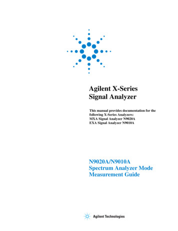
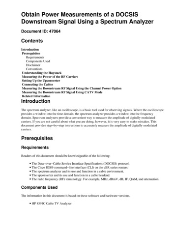
Preparation Real-Time Spectrum AnalysisThe processing performed on each 20MHz patch is determined by the settings provided. Each time a traceis returned, the device waits until the next trace request. For you, the software user, you can choose tocontinuously retrieve traces or manually request them one at a time with the Single and Continuousbuttons found on the Sweep Toolbar.2.6 REAL-TIME SPECTRUM ANALYSISOne of the issues with the standard sweep mode is the “blind time” between each trace. Blind time refersto the time between spectrum sampling. During this time, we are processing the last capture, or viewingthe data. During this time it is possible to miss an event. The picture below shows a missed event in green.In this image we see an event missed due to the blind time between spectrum sampling. With Real-Timespectrum analysis we can prevent this and capture ALL possible events.The BB60C is capable of streaming the full IF bandwidth with no time gaps. If we limit our spans to themaximum instantaneous bandwidth we can now process every spectrum sample for our resulting trace.The BB60C performs overlapping FFTs at an overlapping rate of 50%, covering each point of data with 2FFTs. We take the resulting FFTs and min/max or average them into a final returned trace. The number ofFFT results merged depends on Real-Time Accumulation and the RBW.The minimum signal duration to guarantee the same amplitude as a CW signal (i.e. 100% probability ofintercept) in real-time analysis mode is a function of the resolution bandwidth selected, and is equal to1.5times the FFT interval. The FFT interval is approximately 2 / RBW, so for a 631 kHz RBW, this works out to8
Preparation Zero-Span Analysisabout 4 microseconds. Lower RBWs will require proportionally longer signal duration. However, signals ofeven ¼ this duration will be displayed only 2-3 dB down.See the Spike Software manual for further information on Real-time mode.2.7 ZERO-SPAN ANALYSISZero span analysis allows you to view and analyze signals in the time domain. The BB60 application candisplay amplitude, frequency, and phase vs. time, and display the results through multiple plots. See theSpike Software manual for further information on using Zero Span analysis.2.7.1 Triggering in Zero SpanYou can specify a video trigger, external trigger, or no trigger. Video triggers allow you to begin the sweeponly after a signal exceeds the amplitude specified in the Video Trigger input. This is useful when you needto analyze a periodic transmission.If your transmitter has a trigger output, you can route this to the BB60 trigger in. Select “external trigger”to cause the zero-span sweep to begin after this hardware trigger. You can trigger on the rising edge orfalling edge of a signal. A 3.3V CMOS trigger with 50 ohm output impedance is ideal, but 5V logic with 50ohm output impedance is acceptable. Higher or lower output impedance may work with a short BNCcable, but longer cables may cause issues with reflection.If your trigger output is sensitive to loading, start zero span mode with external trigger enabled beforeconnecting your trigger, to ensure the BB60 trigger port is configured as an input.2.8 SCALAR NETWORK ANALYSISWhen paired with a USB-TG44A, or a USB-TG124A, the BB60C may be used as a scalar network analyzer.This may require a firmware update. In the Spike software, verify you have firmware version 5 or higher.If not, check the Signal hound website for an update. See the Spike software manual for more information.The BB60C is not recommended for scalar network analysis measurements below 100 kHz.9
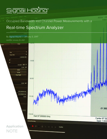
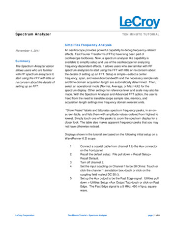
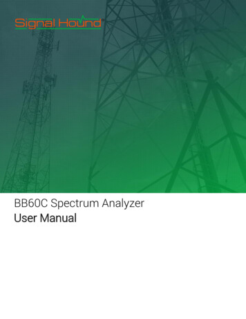
Understanding the BB60C Hardware Front End Architecture3 Understanding the BB60C Hardware3.1 FRONT END ARCHITECTURE3.2 DESCRIPTIONThe BB60C is a two-stage superheterodyne receiver, using two independent intermediate frequencies (IF),selected based on RF input frequency. Each IF has a corresponding distributed element notch filter in theRF section to reduce spurious responses from input signals at the IF frequency. Each RF band also has adistributed element filter buried in the multilayer PCB laminate, engineered to reject that band’s imagefrequencies and reduce LO feed-through. The IF frequencies are 2420 MHz and either 1220 MHz or 1260MHz, depending on serial number. Units produced before Q3 2018 used a 1260 MHz IF.10
Understanding the BB60C Hardware Scalloping LossIntermediate Frequency (IF) used for each range of RF frequenciesRF Frequency Range (MHz)IF Frequency (MHz)LO Frequency Range (MHz)10-189024202430-43101890-31501220 (1260)3110-4370 (3150-4410)3150-511024205570-75305110-60001220 (1260)6330-7220 (6370-7260)Note: Depending on serial numberWherever possible, RF band pass filters were used to reject signals which could result in spurious mixerproducts, such as ½ of the tuned RF frequency, or image frequencies. To reduce spurious signals fromsecond-order intermodulation where filtering was not practical, push-pull amplifiers were used in both thepreamplifier and mixer stages, effectively canceling even-order mixing products. Direct conversion wasused below 10 MHz, completely avoiding the intermodulation products associated with mixing.Gain control is achieved in the BB60C using the front-end attenuator and preamplifier. The front end wasdesigned to provide good spurious-free dynamic range (SFDR) at any reference level, typically better than50 dB.The 14-bit ADC uses built-in dithering to further improve the linearity and decrease spurious responses atthe IF level. Spurs from the ADC are typically 70 dB below the carrier.From the ADC, digitized IF data is handed off to an FPGA where it is packetized. The Cypress FX3 peripheralcontroller streams the packetized data over a USB 3.0 link to the PC, where 80 million, 14-bit ADC samplesper second are processed into a spectrum sweep or I/Q data stream.3.2.1 Residual SignalsA residual signal appears even when there is no signal input. The BB60C has some low level residual signalsat multiples of 10 MHz, typically not visible unless a narrow span ( 10 kHz) is used. These are typically verylow (-130 dBm for a reference level of -50 dBm), except for a few frequencies where signals may be as highas -107 dBm for a reference level of -50 dBm.3.3 SCALLOPING LOSSAn FFT-based spectrum analyzer uses digital resolution bandwidths rather than discrete analog filters.Moving from analog to digital introduces some new terms important to measurement accuracy, like FFTbins, window functions, spectral leakage and scalloping loss. To sum up, an FFT produces an array ofdiscrete frequency bins and their associated amplitude. Real-world signals rarely line up exactly with asingle frequency bin, which can result in some ugly behavior unless a window function is used. Manydifferent window functions are available, with various strengths and weaknesses.11
Understanding the BB60C Hardware Dynamic RangeFor the BB60C, swept modes default to a flat top window, which offers excellent amplitude flatness andtherefore very little scalloping loss, in exchange for a wider resolution bandwidth and longer processingtime. Most RBWs used by the BB60C are from flat top windows, so scalloping loss is negligible.In real-time mode a Nuttall window function is used, which has a narrower bandwidth to reduceprocessing time and level out impulse response. However, when a signal falls halfway between two “bins,”the energy is split between adjacent bins such that the reported “peak” amplitude may be lower by asmuch as 0.8 dB.To get an accurate CW reading using “Marker peak”, flat top RBW shape in swept mode is recommended.In either mode, the “channel power” utility, which integrates the power across any channel bandwidth youspecify, also eliminates this scalloping loss, giving you a full accuracy amplitude reading even in real-timemode.3.4 DYNAMIC RANGEDynamic range has many definitions, but one common definition in spectrum analysis is 2/3(TOI – DANL).A typical number for 1 GHz would be: TOI -19 dBm, DANL -151 dBm (10 Hz RBW). Dynamic range, 2/3(TOI – DANL) 88 dB, and would be a function of RBW, frequency, gain and attenuation settings, etc.3.5 PROTECTING THE BB60C RF INPUTThe BB60C’s input attenuator and front end switches are sensitive to ESD and have a damage level justabove 20 dBm peak (not RMS). Some common events which may lead to front end damage include:1) Applying more than 20 dBm peak power, such as an antenna exposed to a radar pulse.2) ESD from a passive antenna, either from discharge to an antenna element, or from connecting alarge antenna or cable which has built up a static charge.3) Connecting to an active antenna which is already powered on (sudden discharge through the DCblocking cap typically exceeds 20 dBm)For any application which may expose the BB60C to front end damage, including connecting to active orpassive antennas, a coaxial limiter is required to protect the input.A limiter will protect against overpowering the input, typically raising the damage level above 2 watts, aswell as offering significant protection against ESD. It will also offer some protection against the energyspike you get when connecting to equipment with a DC or static voltage present. The energy maysignificantly exceed 20 dBm for several microseconds.Generally, the performance at low input signal levels is just the insertion loss of the limiter, but at highsignal levels there will be some nonlinearity and the resulting intermodulation products. A typical limiterwill have an IP3 around 30 dBm, so for input signals below -10 dBm there should be little to no effect onBB60C linearity.12
Troubleshooting Unable to Find or Open the DeviceFor active antennas, with a built in amplifier, there are some additional concerns, as the amplifier’soperating voltage probably only has a small inductor between the power supply and the output pin. Toavoid damage in this case, power on the BB60C, connect, and then power on the antenna. If this cannotbe done, consider a DC block, followed by a 1 dB pad, followed by a limiter, followed by the BB60C. The 1dB pad can help when a DC voltage at very low impedance is present, by raising the effective impedanceby several ohms.If it is a passive antenna mounted using a long coaxial cable, it may be building up a significant static chargeuntil it is connected. For this reason, it might make the most sense to keep the limiter connected to theantenna rather than the BB60C. A DC block is probably not necessary for passive antennas in most cases.4 TroubleshootingIf you experience a problem with your Signal Hound, please try these troubleshooting techniques beforecontacting us.4.1 UNABLE TO FIND OR OPEN THE DEVICEEnsure the device is plugged in and the green light is on. If it is not, unplug then plug in the device. Oncethe green light turns on, use the File menu to try to connect the device again.4.1.1 The Device Light is Green and Still Won’t ConnectThis is often the case when the device is plugged in when a PC has been turned on. We recommend leavingthe device unplugged when you turn off your PC. If this is the case, a power cycle will solve this issue.4.1.2 A Power Cycle Does Not Fix the ProblemIf a power cycle still does not allow you to connect the device, it is possible the device drivers were notsuccessfully installed. See the Driver Installation section for information about the BB60 drivers.4.2 THE DEVICE IS NOT VALIDIn the event the device ceases to operate or becomes corrupted, the application might tell you the devicedoes not appear to be valid. Before contacting us, attempt to power cycle the device and restart yourcomputer to ensure nothing else is causing this issue. If the issue persists, please contact us.5 Calibration and AdjustmentCalibration software is available for the BB60C at no charge, but requires specialized equipment normallyonly found in calibration labs. Contact Signal Hound for more information regarding calibration softwareand required equipment, or to schedule a calibration.13
BB60C Specifications The Device is Not Valid6 BB60C SpecificationsThe following preliminary specifications are based on being in the Preset condition, using internal timebase, video processing set for average and power, plus VBW, sweep, gain, and attenuation in the defaultauto mode.Frequency range9 kHz to 6 GHzStreaming Digitized I/Q250 kHz to 27 MHz of selectable IF bandwidth that is amplitudecorrectedResolution Bandwidths (RBW)10 Hz to 10 MHzInternal Timebase Accuracy 1 ppm per yearSweep Speed (RBW 10 kHz)24 GHz/secAmplitude (RBW 100 kHz)Range: 10dBm to Displayed Average Noise Level (DANL)Absolute Accuracy 2.0 dB (Non-Native(Flattop) RBWs) 2.0 dB/-2.6 dB (Native(Nuttall) RBW’s –faster DSP)RF InputfrequencyVSWRattunedLO Leakage at RF InputDisplayed Average Noise Level(DANL)*Residual Responses* 3.0:1 typical ( 10 dB attenuation) 1.5:1 typical ( 10 dB attenuation)-80 dBm (preamp on†)Input Frequency Range9 kHz to 500 kHz500 kHz to 10‡ MHz10‡ MHz to 6 GHzdBm/Hz-140-154-158 1.1dB/GHzRef Level -50 dBm, 0 dB AttenuationInput Frequency Residual LevelRange500 kHz to 6 GHz-106 dBm500 kHz to 6 GHz14-103dBmApplicable SerialPrefix4119, 4150, 4226,42965047 and higher
BB60C Specifications The Device is Not ValidSpurious Mixer Responses*SSB Phase Noise at 1 GHz CenterFrequency*Recommended Computer-50dBc(any ref level from 10dBm to -50dBm, in 5dB increments, inputsignal 10 dB below ref level, and 30kHz RBW)Offset Frequency100 Hz1 kHz10 kHz100 kHz1 MHzdBc/Hz-70-76-83-93-117Windows 7 or 8 operating system or Ubuntu Linux 18.04, 8 GBof RAM, Intel i7, 3rd generation (Ivy Bridge) or later with a quadcore processor, one USB 3.0 port, and one adjacent USB 2.0 orUSB 3.0 port.Note: RF recording using streaming I/Q bandwidths 8 MHzrequires the computer’s mass storage drive to have at least250MB/sec of sustained write speed such as an SSD, RAID-0, orRAID-5.Synchronization ( 20 MHz IBW)1 PPS GPS input port enables 50ns time-stampingOperating Temperature32 F to 149 F (0 C to 65 C) Standard;-40 F to 149 F (-40 C to 65 C) for Option-1WeightNet, 1.10 lbs. (0.50 kg)Size8.63” x 3.19” x 1.19” (219mm x 81mm x 30mm)Power(1) USB 3.0 port and (1) adjacent USB 2.0 or USB 3.0 portControl and CommunicationUSB 3.0 serial busOption 10 Input Voltage4.75V – 5.25V, 200 mVpp ripple.*DANL, Residual Responses, Spurious Mixer Responses, and Phase Noise specifications apply only at 20 C to25 C. Typical variations, over the analyzer’s operating temperature, from the specifications at 20 C to 25 C arepublished in Appendix: Typical Performance Characteristics of the BB60C.** IP2 and IP3 typical performance specifications can be found in the Appendix: Typical PerformanceCharacteristics of the BB60C.† Preamp is on for reference level -20 dBm or manual gain settings 2-3‡ Below 500 kHz span, DANL band break occurs at 16 MHz rather than 10 MHz15
Warranty and Disclaimer Warranty7 Warranty and Disclaimer 2013-2017 Signal Hound. All rights reserved.Reproduction, adaptation, or translation without prior written permission is prohibited,except as allowed under the copyright laws.7.1 WARRANTYThe information contained in this manual is subject to change without notice. Signal Hound makes nowarranty of any kind with regard to this material, including, but not limited to, the implied warranties ormerchantability and fitness for a particular purpose. Signal Hound shall not be liable for errors containedherein or for incidental or consequential damages in connection with the furnishing, performance, or useof this material. This Signal Hound product has a warranty against defects in material and workmanshipfor a period of two years from date of shipment. During the warranty period, Signal Hound will, at itsoption, either repair or replace products that prove to be defective.7.2 WARRANTY SERVICEFor warranty service or repair, this product must be returned to Signal Hound. The Buyer shall payshipping charges to Signal Hound and Signal Hound shall pay UPS Ground, or equivalent, shipping chargesto return the product to the Buyer. However, the Buyer shall pay all shipping charges, duties, and taxes, toand from Signal Hound, for products returned from another country.7.3 LIMITATION OF WARRANTYThe foregoing warranty shall not apply to defects resulting from improper use by the Buyer, Buyersupplied software or interfacing, unauthorized modification or misuse, operation outside of theenvironmental specifications for the product. No other warranty is expressed or implied. Signal Houndspecifically disclaims the implied warranties or merchantability and fitness for a particular purpose.7.4 EXCLUSIVE REMEDIESThe remedies provided herein are the Buyer’s sole and exclusive remedies. Signal Hound shall not be liablefor any direct, indirect, special, incidental, or consequential damages, whether based on contract, tort, orany other legal theory.7.5 CERTIFICATIONSignal Hound certifies that, at the time of shipment, this product conformed to its published specifications.16
Appendix Credit Notice7.6 CREDIT NOTICEWindows is a registered trademark of Microsoft Corporation in the United States and other countries.Intel and Core are trademarks or registered trademarks of the Intel Corp. in the USA and/or othercountries.Ubuntu is a registered trademark of Canonical, Ltd. in the United States and/or other countries.8 Appendix8.1 TYPICAL PERFORMANCE CHARACTERISTICSOF THE BB60CBelow are characteristics of the BB60C which have shown to be typical. These are not hard specificationsbut show the typical performance in a few aspects not covered in our official specs.The official BB60C device specifications can be found in this document under the section titled BB60CSpecifications.8.1.1 Third Order Intercept (TOI)Freq(GHz)12.545.5Typical IIP3 at Specified Reference Level (dBm) Gain and Atten AUTOR.L. 0.621.831.0*Typical Performance of internal step attenuator171032*32*32*32*
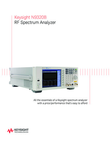
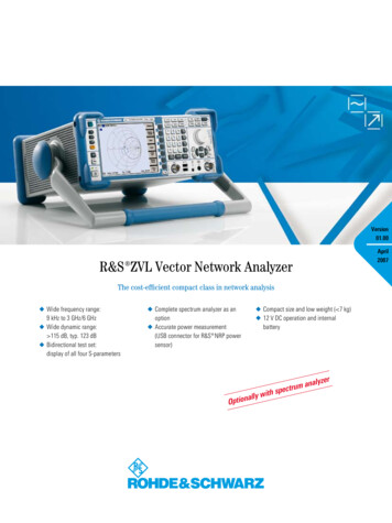
Appendix Typical Performance Characteristics of the BB60C8.1.2 Typical Amplitude Accuracy8.1.3 Typical Displayed Average Noise Level18
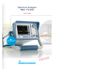
Appendix Typical Performance Characteristics of the BB60C8.1.4 Typical Performance over Temperature8.1.4.1 Spurious Mixer Responses*-50050010001500200025003000-40 CHarmonic Responses (dBc)-30 C-20 C-10 C0C-6010 C21 C32 C43 C54 C-7065 CFrequency (MHz)*Signal 10 dB below reference level. To calculate IP2 at a given frequency, subtract this number from signallevel (e.g. -30 dBm reference level would be a -40 dBm signal. Subtract e.g. -64dB @ 2 GHz for an IP2 of 24 dBm).8.1.4.2 Phase NoiseTypical Phase Noise Across Temperature at 1GHz-40 C-60-651001,00010,000100,000-30 C-20 CdBc/Hz-70-10 C-750C-8010 C21 C-8532 C-9043 C-9554 C-10065 COffset (Hz)19
Appendix Typical Performance Characteristics of the BB60C8.1.4.3 Displayed Average Noise Level Change over TemperatureTypical DANL change (dB)2Change from 25 C ure (deg C)* Shown for gain 3, attenuator 0 dB. For auto gain/attenuator settings at cold temperatures, a referencelevel of -55 dBm may be required for maximum sensitivity, instead of the usual -50 dBm.8.1.4.4 Residual Signals over TemperatureTemperature typically has little effect on residual signal levels.20
Hound spectrum analyzers. The description of how to use the software with the BB60C is now found in the Spike software manual. 2 Preparation The BB60C is a real-time high-speed spectrum analyzer communicating with your PC over a USB 3.0 Super Speed link. It has 27 MHz of real-time bandwidth, tunes from 9 kHz to 6 GHz, collects 80 million samples