Transcription
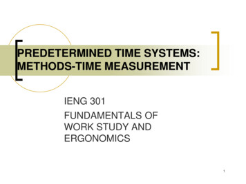
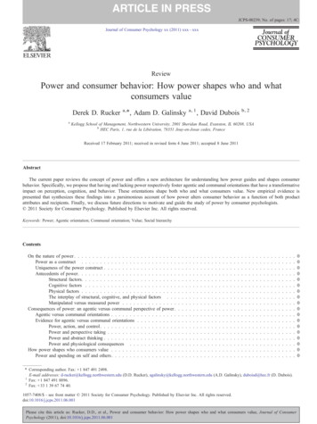
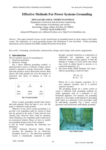
WSEAS TRANSACTIONS on BUSINESS and ECONOMICSDon Jacob and K. NithiyananthanEffective Methods For Power Systems GroundingDON JACOB AND K. NITHIYANANTHANDepartment of electrical and electronics engineeringBirla institute of technology and science,Knowledge village, Dubai, Post Box No 500022UNITED ARAB EMIRATESdonjacob10@gmail.com nithiieee@yahoo.co.in http://www.bitsdubai.comAbstract –This paper primarily focuses on the classification of grounding based on rated voltage of the faultysystem. The importance of a good grounding design with illustrations is also described. Useful groundinginformation can be obtained from IEEE standard 80 and the Green Book.Key-words – Grounding, classifications, characteristics, design, rated voltage, fault current, equipotential.through a ground connection or connections ofsufficiently low impedance and havingsufficient current carrying capacity to limit thebuildup of voltages to levels below that whichmay result in undue hazard to persons or toconnected equipment” [1].2. The Green Book (IEEE Standard 142) states effective grounding is achieved when:1. IntroductionThe two primary reasons for grounding are:1. Protection and Safety2. Reference VoltageFig 1 shows different grounding symbols. Asignal ground is used as a reference voltage, chassisground is required to assuage electrostatic voltagesand earth ground is used to drain fault currents. Bothchassis and earth grounds are serve the purpose ofprotection and safety of humans as well asappliances.3X1 Xo (1)Ro X12 (2)Where, Ro is zero sequence resistance, Xo iszero sequence reactance and X1 is positivesequence reactance.The grounding design for a whole system orcircuit is different from grounding methods forsingle equipment such as a generator or anyhousehold appliance. For instance, the groundingdesign for a skyscraper would depend on groundinggrids where as a generator in the skyscraper couldbe individually grounded. Fig 2 shows severalgenerators and transformers individually grounded.Fig 1 Ground SymbolsPower systems grounding include both chassisand earth grounds. Since the topic is very vast, thepaper is confined to earth grounds.Objective of any power system grounding is toprovide a low impedance path for current to draininto the ground at the point of fault with the leastclearing time. However there could be situationswhere obtaining a low impedance path would not bean economical solution. Hence we have to modifyour grounding design to best fit the situation.It will be worth comparing the following twodefinitions:1. NESC (National Electrical Safety Code)provides the definition for an effectivelygrounded system as, “An effectively groundedsystem is intentionally connected to earthISSN: 1109-9526Fig 2 Solid Ground151ssue 5, Volume 5, May 2008
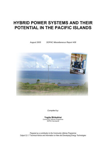
WSEAS TRANSACTIONS on BUSINESS and ECONOMICSDon Jacob and K. NithiyananthanThis paper explains advantages of a goodgrounding design and most common methods usedfor grounding power systems. Effort is made toclassify and compare several grounding designs.The latter part of this paper provides a generalalgorithm for designing of grounding powersystems. In most cases, to best serve the purpose ofa grounding system, the design should be ‘situationspecific’.Fig 3 Faulty Ground Connections2. Importance of good groundingdesignTherefore the short circuit current drainedthrough the Subpanel ground will damage allappliances connected to the Subpanel.2. In transmission line towers, earth wires are usedto dissipate the current induced on the lines dueto lightning. Adequate distance or gaps shouldbe provided between the arms of the tower linesand the earth wire, to ensure prevention of“Back flashover”. Back flashover is the arcingbetween earth wire and a single phase wire.Note that here the earth wire is the transmissiontower itself [2].A good grounding system requires a high currentcapacity path with relatively low impedance at thefundamental frequency so that voltages developedunder high fault current conditions are nothazardous. It is very easy to makes a low impedanceconnection to ground. However problems arise assoon as equipments are connected to it. This couldbe other near by grounded systems and usually bythe equipment of installation itself.Following are a few examples to consolidate theabove:1. Fig 3 shows chassis of several computers loopedtogether to a common ground. In the figure, thetransmission line is connected to the serviceentrance panel which is connected to thesubpanel. Note that not all the loops in thefigure are safe. It is considered safe only forthose loops in which the chassis are connectedto the same ground. In other words, thosechassis that are looped between the two panelsare unsafe since the panels are groundedseparately. This may severely damage theequipments connected to the sub panel. This isbecause, if at any instant there is any fault onchassis C then the short circuit caused in thesystem could draw high currents. Now, in thepositive cycle of the AC, let the current flowfrom the Subpanel to the Service entrance. Thusthe short circuit current would be drainedthrough the ground in the service entrance. Butduring the negative cycle of the AC, the shortcircuit current drawn from the service entrancewill be greater than the circuit ratings of allequipments used in the subpanel.ISSN: 1109-9526Fig 4 Transmission Line Towers3. Another example would be, in designing ofgrounding system care should be taken to avoidparallel paths. In following figure we can seethat, the fault current IF in first case is equal tothe maximum grid current IG. However in thesecond case, the total fault current, IF at thepoint of fault is the sum of the currents IG and Ie.In other words, ground rods or grids should notbe connected parallel to the ground instead theyshould be connected in series or the ground rodshould be individually connected to the groundthrough an earth pit [3].152ssue 5, Volume 5, May 2008
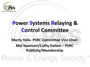
WSEAS TRANSACTIONS on BUSINESS and ECONOMICSDon Jacob and K. Nithiyananthan3.1 Ungrounded SystemsThey were thought to be the most stable groundedtype of systems because only when there is aground, there is a low potential. Hence the faultcurrent would be very high in such situations. Toavoid such high fault currents ungrounded systemswhere thought to be good. Also effects of harmonicson an ungrounded system can be ignored due to thefact that since the system is ungrounded theharmonics would eventually die out within thesystem itself. Finally, for an ungrounded systemthere is no source of interference from othergrounded systems. However, ungrounded systemsare very poor in protecting transient overvoltage.Due to these voltages there could be faultsbeginning from one part of the circuit andpropagating throughout the circuit. In these casesthe insulation of the conductors would graduallydeteriorate and would break down eventually. Suchfaults would go unnoticed until they occur. Thus weswitch over to grounded systems.Fig 5 Equipotential silhouettes of a grounding grid with orwithout ground rods3. Classification of grounding systemsDesign of grounding system could vary greatlydepending on situation, application and geographyof the site. For instance, if the system to begrounded is of high voltage then low impedancegrounding could lead to potential hazards relating tofire. The geography of the site is considered sincethe soil resistivity could alter the impedance of thegrounding system.Classification of grounding systems (fig 6)could be evasive. Here the focus is on classificationof grounding systems with respect to the operatingvoltage of the system.3.2 Grounded SystemsThere are basically two ways to ground a system.Neutral Grounding is the most common method. Itcould be used to ground an entire system and itcould also be used to ground particular equipmentslike generators, transformers etc [4]. These methodsare usually employed at a power generation stationor a substation. Neutral grounding primarily focuseson grounding system ELV systems and EHVsystems. Non neutral grounding methods are thoseused for grounding systems not solely involved topower generation or distribution. The groundings ofbuildings, substations and the utility grid as a wholecould be considered as non-neutral grounding.These types of grounding are primarily focused onmedium voltage and low voltage systems. Theycould also vary according to the regions or countriesin which they are installed.Fig 7 shows grounding systems involvingimpedances. Apart from the impedances involved,circuit breakers are also shown in combination withgrounding. It is interesting to note that thegrounding conductor is never tripped. In most casesthe breakers trip only the live conductors and not theneutral or earth conductors. A neutral conductorshould not be tripped alone. If tripped it should betripped along with the live conductors.Fig 6 Classifications of Grounding SystemsISSN: 1109-9526153ssue 5, Volume 5, May 2008
WSEAS TRANSACTIONS on BUSINESS and ECONOMICSDon Jacob and K. Nithiyananthan3.3 Solid GroundingSolid grounding systems are those that are directlygrounded with no impedance. Generally, generatorsare preferred with this type of ground for providingfast clearing time of high fault currents. It could beattributed to the idea that a fault at the power sourcewould be drained instantaneously at the source itself[Fig 2].3.4 Low Resistance GroundingA resistance grounded system is one in whichresistance is added along the grounding conductor tokeep faults currents within limits. The objective oflimiting the fault current here is primarily focusedon protecting the insulation of the groundingconductor. Recent suggestions indicate preferencefor low resistance grounding of generators thansolid grounding, to give the system better reliabilityagainst overvoltage and harmonics. Resistancegrounded systems are best suited for voltages below150 Volts.Fig 7 Grounding Systems involving impedances3.5 High Resistance GroundingSimilar to low resistance grounding but differs inthe value of resistance. Here the value of resistanceis comparatively higher. This would violate theobjective of grounding. Low impedance is vital inthe sense that current should always choose thegrounding conductor to flow at the point of fault.Adding a high resistance would not serve thispurpose and is contradictory to the assertion above.But this method of grounding is preferred forlimiting of fault currents for medium voltagesystems typically in the range of 150 to 600 Volts.Occurrence of arc formation is highly unlikely forvoltages below 150 volts and even if an arc isformed, it cannot be sustained [5].Typical High Resistance Grounding Systems arefound in petroleum and chemical industries. Herearc suppressions and prevention of arcs are veryimportant due to presence of highly inflammablesubstances. A notable disadvantage of highresistance grounding is the amount of time requiredto drain out the fault current is relatively more thanin low resistance or solidly grounding systems.ISSN: 1109-95263.6 Hybrid High Resistance GroundingThere are essentially two reasons for preferring ahybrid grounding system:1. The fault clearing time in a high resistancegrounding scheme is higher than in lowresistance grounding schemes.2. Advantage of a low resistance groundingscheme was mentioned above. However thisvery boon to low resistance grounded system isa limitation too. This is because when severalgenerators and/or transformers are groundedsimultaneously the equivalent impedance of thesystem would be lower, since all theseimpedances are in parallel, see fig 8. This couldresult in a very high increase of fault current ofthe system in the order of 1000 Amperes. Analternative solution to this could be to provide aneutral bus for multiple power sources andground the neutral bus through a resistance, seefig 9 [6]. For these reasons the best solutionwould be to combine the two groundingschemes – a hybrid of low resistance groundingand high resistance grounding. HHRG systemsare best suitable in medium voltage applicationsaround 1 to 20 kV [7] [8].154ssue 5, Volume 5, May 2008
WSEAS TRANSACTIONS on BUSINESS and ECONOMICSDon Jacob and K. NithiyananthanFig 8 Individually Grounding Power SourcesFig 11 Grounding for high frequency harmonicsStill another form of classification groundedsystems that we could think of could be: Impedanceand Non Impedance grounded systems. In such aclassification non impedance grounded systemwould be a solidly grounded system and groundingsystems involving impedance would be resistanceand reactance grounded systems. A typicalapplication of this grounding could be found inaircrafts where the power generated is at 400Hzcompared to the normal 50Hz. This is because; thegenerator size reduces drastically as the frequencyincreases as evident from the formula below:Fig 9 Grounding Several Power Sources through a neutralbus.Fig 10 shows an application of such a groundingscheme installed in a paper mill involving 13.8 kVgenerators [9].EMF NAIBsinθ (3);θ ωt (4);ω 2πf (5).Where N is the number of turns, A is the area ofrotating coil, I is the current flowing through thecoil, B is the magnetic field, θ is the angle betweennormal of the coil plain and magnetic field, t is thetime and ω is the angular frequency of the coil.Table 1 summarizes the above mentionedgrounding schemes which would provide betterunderstanding.Fig 10 Hybrid High Resistance Grounding SystemsTable 1 Grounding Systems: ComparisonMETHODS OF SYSTEM GROUNDING3.7 Ground Fault NeutralizerISSN: onomics MaintenanceWorstpoorpoorBestCharacteristicsAlso called Peterson’s Coil, this is primarily usedfor suppressing arcs caused in the groundingconductor with the help of back EMFs of theinductor. Hence they are also known as Peterson’sArc Suppression Coil Grounding. This could beused in parallel w
2. The Green Book (IEEE Standard 142) states - effective grounding is achieved when: 3X. 1 Xo (1) R. o X. 1 2 (2) Where, R. o is zero sequence resistance, Xo is zero sequence reactance and X1 is positive sequence reactance. The grounding design for a whole system or circuit is different from grounding methods for single equipment such as a generator or anyFile Size: 539KBPage Count: 10