Transcription
Installation Instructions &Technical HandbookJANUARY 2018IH-1900www.tyco-fire.com1400 Pennbrook Parkway, Lansdale, PA 19446 Telephone 1-215-362-0700 2018 Johnson Controls. All rights reserved. All specifications and other information shown were current as of document revision date and are subject to change without notice.
TABLE OF CONTENTS1. GENERAL DESCRIPTION . . . . . . . . . . . . . . . . . . . . . . . . . . . . . . . . . . 4INTRODUCTION . . . . . . . . . . . . . . . . . . . . . . . . . . . . . . . . . . . . . . . . . . . 4Advantages . . . . . . . . . . . . . . . . . . . . . . . . . . . . . . . . . . . . . . . . . . . . . . . 5Training and Demonstration . . . . . . . . . . . . . . . . . . . . . . . . . . . . . . . . . 5Trademarks Appearing In This Manual . . . . . . . . . . . . . . . . . . . . . . . . 52. LISTINGS AND APPROVALS . . . . . . . . . . . . . . . . . . . . . . . . . . . . . . . 7LISTINGS/APPROVALS (WHERE TO USE) . . . . . . . . . . . . . . . . . . . . . 7Underwriters Laboratories Inc. (UL) andUnderwriters Laboratories Inc. (C-UL) For Use In Canada . . . . . . . 7Concealed Installations (UL) . . . . . . . . . . . . . . . . . . . . . . . . . . . . . . 7Concealed Installations (C-UL) . . . . . . . . . . . . . . . . . . . . . . . . . . . . 8Exposed Installation - General (UL & C-UL). . . . . . . . . . . . . . . . . . 8Smooth, Flat, Horizontal, Fixed Ceilings Exposed Installations (UL & C-UL) . . . . . . . . . . . . . . . . . . . . . . . . . 8Unfinished Basements - Exposed Installations. . . . . . . . . . . . . . 10Residential Dry Pipe Systems (UL) . . . . . . . . . . . . . . . . . . . . . . . . 14Air Plenums (UL). . . . . . . . . . . . . . . . . . . . . . . . . . . . . . . . . . . . . . . . 16Garage Installations (UL) . . . . . . . . . . . . . . . . . . . . . . . . . . . . . . . . 16System Risers (UL). . . . . . . . . . . . . . . . . . . . . . . . . . . . . . . . . . . . . . 17Underground Water Pressure Service (UL & C-UL) . . . . . . . . . . 18Outdoor Installations. . . . . . . . . . . . . . . . . . . . . . . . . . . . . . . . . . . . 22Concealed Installations (FM). . . . . . . . . . . . . . . . . . . . . . . . . . . . . 22Exposed Installations Smooth, Flat, Horizontal Ceilings (FM). . . . . . . . . . . . . . . . . . . . . 22System Risers (FM) . . . . . . . . . . . . . . . . . . . . . . . . . . . . . . . . . . . . . 24The Loss Prevention Council (LPCB) . . . . . . . . . . . . . . . . . . . . . . 24Additional Approvals . . . . . . . . . . . . . . . . . . . . . . . . . . . . . . . . . . . . . . 25Ordinary Hazard Installations . . . . . . . . . . . . . . . . . . . . . . . . . . . . . . 253. TECHNICAL DATA . . . . . . . . . . . . . . . . . . . . . . . . . . . . . . . . . . . . . . . 27TYCO CPVC Specifications . . . . . . . . . . . . . . . . . . . . . . . . . . . . . . . . . 27Pipe. . . . . . . . . . . . . . . . . . . . . . . . . . . . . . . . . . . . . . . . . . . . . . . . . . . 27Fittings. . . . . . . . . . . . . . . . . . . . . . . . . . . . . . . . . . . . . . . . . . . . . . . . 28Solvent Cement . . . . . . . . . . . . . . . . . . . . . . . . . . . . . . . . . . . . . . . . 28Product Ratings and Capabilities . . . . . . . . . . . . . . . . . . . . . . . . . . . 28Ambient Temperature and Heat Sources. . . . . . . . . . . . . . . . . . . 28Pressure Rating . . . . . . . . . . . . . . . . . . . . . . . . . . . . . . . . . . . . . . . . 28Friction Loss. . . . . . . . . . . . . . . . . . . . . . . . . . . . . . . . . . . . . . . . . . . 29Thermal Expansion – U.S. Units. . . . . . . . . . . . . . . . . . . . . . . . . . . 30Thermal Expansion – Metric Units. . . . . . . . . . . . . . . . . . . . . . . . . 32Physical and Thermal Properties . . . . . . . . . . . . . . . . . . . . . . . . . . . . 43Permissible Bending Deflections. . . . . . . . . . . . . . . . . . . . . . . . . . 43Support and Hanger Requirements . . . . . . . . . . . . . . . . . . . . . . . . . . 48Pipe Bracing with Standard Band Hanger . . . . . . . . . . . . . . . . . . 49Hanger/Support Spacing . . . . . . . . . . . . . . . . . . . . . . . . . . . . . . . . 49Vertical Restraint. . . . . . . . . . . . . . . . . . . . . . . . . . . . . . . . . . . . . . . 50Chemical Compatibility . . . . . . . . . . . . . . . . . . . . . . . . . . . . . . . . . . . . 52Paint . . . . . . . . . . . . . . . . . . . . . . . . . . . . . . . . . . . . . . . . . . . . . . . . . . . . 52
TABLE OF CONTENTS4. INSTALLATION . . . . . . . . . . . . . . . . . . . . . . . . . . . . . . . . . . . . . . . . . . 53Handling & Storage of TYCO CPVC . . . . . . . . . . . . . . . . . . . . . . . . . . 54Handling - Pipe and Fittings. . . . . . . . . . . . . . . . . . . . . . . . . . . . . . 54Storage - Pipe & Fittings . . . . . . . . . . . . . . . . . . . . . . . . . . . . . . . . 54Handling - Solvent Cements. . . . . . . . . . . . . . . . . . . . . . . . . . . . . . 55Storage - Solvent Cements. . . . . . . . . . . . . . . . . . . . . . . . . . . . . . . 55Solvent - Cement Spills. . . . . . . . . . . . . . . . . . . . . . . . . . . . . . . . . . 55Joining CPVC Pipe and Fittingswith One-Step Solvent Cement . . . . . . . . . . . . . . . . . . . . . . . . . . . . . 56Estimating Cement Requirements. . . . . . . . . . . . . . . . . . . . . . . . . 56Cutting. . . . . . . . . . . . . . . . . . . . . . . . . . . . . . . . . . . . . . . . . . . . . . . . 57De-burring and Beveling. . . . . . . . . . . . . . . . . . . . . . . . . . . . . . . . . 57Solvent Cement Application. . . . . . . . . . . . . . . . . . . . . . . . . . . . . . 57Assembly. . . . . . . . . . . . . . . . . . . . . . . . . . . . . . . . . . . . . . . . . . . . . . 59Set and Cure Times. . . . . . . . . . . . . . . . . . . . . . . . . . . . . . . . . . . . . 59TFP-500 or TFP-600 Solvent Cement Cure Times. . . . . . . . . . . . 60System Acceptance Testing (Hydrostatic Pressure Test) . . . . . 61Limited Pressurized Air or Nitrogen Testing Allowance. . . . . . . 61Joining Pipe and Fittings in Adverse Conditions . . . . . . . . . . . . . . . 62In Cold Weather . . . . . . . . . . . . . . . . . . . . . . . . . . . . . . . . . . . . . . . . 62In Hot Weather . . . . . . . . . . . . . . . . . . . . . . . . . . . . . . . . . . . . . . . . . 63Transition to Other Materials . . . . . . . . . . . . . . . . . . . . . . . . . . . . . . . 63Brass Threaded Connections. . . . . . . . . . . . . . . . . . . . . . . . . . . . . 64Sprinkler Installation in Rapid Seal Adapter (RSA) Fittings 64Gasket Replacement in Rapid Seal Adapter (RSA) Fittings 65Grooved Coupling Adapter Connections . . . . . . . . . . . . . . . . . . . 66Penetrating Fire Rated Walls & Partitions . . . . . . . . . . . . . . . . . . . . 66Freeze Protection . . . . . . . . . . . . . . . . . . . . . . . . . . . . . . . . . . . . . . . . . 67Use of Dry Type Sprinklers. . . . . . . . . . . . . . . . . . . . . . . . . . . . . . . 67Use and Cautions with Glycerin Antifreeze . . . . . . . . . . . . . . . . . 67Batt Insulation Requirements and Suggestions . . . . . . . . . . . . . 68Batt Insulation Installation Recommendations. . . . . . . . . . . . . . 68Cut-in Procedure for System Modification and Repair . . . . . . . . . 695. VISIT WWW.TYCO-FIRE.COM . . . . . . . . . . . . . . . . . . . . . . . . . . . . . 716. APPENDIX A - PIPE FITTINGS . . . . . . . . . . . . . . . . . . . . . . . . . . . . 727. APPENDIX B - DO’S AND DON’TS . . . . . . . . . . . . . . . . . . . . . . . . . 908. IMPORTANT INFORMATION . . . . . . . . . . . . . . . . . . . . . . . . . . . . . . 92Important Information withRegards to Your TYCO CPVC Fire Sprinkler System . . . . . . . . . . . . 92Notification to Jobsite Building Trades . . . . . . . . . . . . . . . . . . . . . . . 93
4GENERAL DESCRIPTIONINTRODUCTIONThis Installation Handbook refers to TYCO CPVC Pipe and Fittings producedby Johnson Controls. TYCO CPVC Pipe and Fittings are produced usingBlazeMaster CPVC compound. When reference to NFPA Standards is madein this Installation Handbook, the current edition of the relevant code isused. This Installation Handbook contains the criteria for installation(including system design, handling, and storage) of BlazeMaster CPVCpiping systems in accordance with the applicable Listing/Approvalagencies. Additionally, this handbook contains general piping practicesand other installation suggestions that may not be required to satisfy theapplicable Listing/Approval agencies. To differentiate between a requirementand a suggestion, use the following definitions:SHALL or MUST – T he use of the words “shall” or “must” indicates amandatory requirement of the Listings/Approvals.SHOULD or MAY – T he use of the words “should” or “may” indicatesa recommendation that is strongly advised, but notrequired to meet the Listings/Approvals.This handbook is intended as a supplement to basic, fundamental knowledgerelating to the installation and/or repair of CPVC fire sprinkler systems.Before commencing installation, a user should understand this InstallationHandbook and confirm applicable National Fire Protection Association(NFPA) standards, the National Building Code of Canada (as applicable), andlocal approval and installation requirements for CPVC fire sprinkler systems.NOTICEThe TYCO CPVC Pipe and Fittings described herein must be installed andmaintained in compliance with this Installation Handbook and with theapplicable standards of the National Fire Protection Association, in additionto the standards of any authorities having jurisdiction. Failure to do so mayimpair the performance of the TYCO CPVC Pipe and Fittings.The owner is responsible for maintaining their fire protection system anddevices in proper operating condition. The installing contractor or productmanufacturer should be contacted with any questions.It is the designer’s responsibility to select products suitable for the intendedservice and to ensure that pressure ratings and performance data are notexceeded. Material selection should be verified to be compatible for thespecific application. Designers and Installers must read and understand theinstallation instructions in this handbook.Never remove any piping component or modify any piping deficiencieswithout first depressurizing and draining the system.WARNINGNever use compressed air or nitrogen in lieu of or to replace the requiredhydrostatic system acceptance testing. Any pre-testing performed withlow pressure air or nitrogen should follow the recommendations on p. 61.System failure when using high-pressure compressed air or nitrogen mayresult in property damage, serious injury, or death.
GENERAL DESCRIPTIONADVANTAGESTYCO CPVC Pipe and Fittings are designed specifically for fire sprinklersystems and provide the following advantages over traditional sprinklerpiping systems: Increased hydraulic capabilities (C-Factor 150) No pre-cutting and expensive fabrication required Pipe/Fittings (slip style only) - NSF-pw listed for use in pressure ratedpotable water piping systems Can easily be connected to other sprinkler piping systems Flexibility in the piping for greater ease of installation Resistant to rust, scale, and foreign contaminant build up Inexpensive tools required for installation Easily repaired or modified on site Easily transported and handled Resists sweating and condensationTRAINING AND DEMONSTRATIONJohnson Controls strongly recommends that installers receive hands ondemonstration in the proper procedure(s) for installation of BlazeMasterfire sprinkler systems. On-site demonstration in proper pipe preparation,solvent cementing, proper handling of CPVC and installation instruction areavailable from Johnson Controls at no charge. Upon completion of the TYCOdemonstration program, Johnson Controls will issue a completion card tothe persons successfully finishing the required subject matter. This card isto be carried when working on TYCO CPVC systems. For information abouton-site demonstration, contact your local Johnson Controls DistributionCenter or your Johnson Controls sales representative.TRADEMARKS APPEARING IN THIS MANUALTYCO . . . . . . . . . . . . . . . . . . . . . . . registered trademark of Johnson ControlsHEAD SET registered trademark of Johnson ControlsBlazeMaster. . . . . . . . . . . . . . registered trademark of The Lubrizol CorporationCaulk and Walk registered trademark of The Lubrizol CorporationSOFFI-STEEL registered trademark of Grice EngineeringTEFLON registered trademark of DupontOATEY registered trademark of OateyGREAT WHITE registered trademark of OateyCRISCO registered trademark of J.M. Smucker Co.FBC System Compatible Program registered trademark ofThe Lubrizol Corporation51
6GENERAL DESCRIPTION
LISTINGS & APPROVALS7LISTINGS/APPROVALS (WHERE TO USE)For verification of Listings and Approvals, consult the current UL FireProtection Equipment Directory, C-UL Products Certified for CanadaDirectory, Factory Mutual Research Approval Guide, or LPCB List ofApproved Fire Security Products and Services Guide.Johnson Controls manufactures CPVC pipe and fittings using Lubrizol’sBlazeMaster compound as a licensee of The Lubrizol Corporation.UNDERWRITERS LABORATORIES INC. (UL) ANDUNDERWRITERS LABORATORIES INC. (C-UL) FOR USE IN CANADATYCO CPVC Pipe and Fittings are UL and C-UL Listed for use in: L ight Hazard and residential occupancies as defined in the Standardfor Installation of Sprinkler Systems, NFPA 13 R esidential occupancies as defined in the Standard for the Installationof Sprinkler Systems in Low-Rise Residential Occupancies up to FourStories in Height, NFPA 13R R esidential occupancies as defined in the Standard for Installation ofSprinkler Systems in One and Two Family Dwellings and ManufacturedHomes, NFPA 13D A ir plenums, as defined by the Installation of Air Conditioning andVentilating Systems, NFPA 90A Underground Water Pressure Service, NFPA 24 System risers in accordance with NFPA 13, 13R, and 13D See UL Fire Protection Equipment Directory, categories VIWT and HFYH. S ee C-UL Products Certified for Canada Directory, categories VIWT7and HFYH7.TYCO fire sprinkler systems shall be employed in wet-pipe systems only. (Awet pipe system contains water or water and glycerin (anti-freeze solution)and is connected to a water supply so that the water or water and glycerin(anti-freeze solution) will discharge immediately when a sprinkler is opened.)National Fire Protection Association Standards 13, 13R, 13D and NFPA24, in addition to the standards of any other authorities having jurisdiction,must be referenced and followed for design and installation requirementsin conjunction with this installation handbook.Concealed Installations (UL) I n accordance with the UL Listing, protection shall be provided for TYCOCPVC Pipe and Fittings. The minimum protection shall consist of eitherone layer of 3/8 in. (9,5 mm) thick gypsum wallboard, 1/2 in. (12,7 mm)plywood soffits, or a suspended membrane ceiling with lay-in panels ortiles having a weight of 0.35 pounds per sq. ft. (1,7 kg per sq. meter) wheninstalled with metallic grids. For residential occupancies defined in NFPA13D and 13R, the minimum protection may consist of one layer of 1/2 in.(12,7 mm) plywood.2
8LISTINGS & APPROVALSListed Quick Response, standard or extended coverage, 225 F(107 C) maximum temperature rated sprinkler or Listed Residential 225 F(107 C) maximum temperature rated sprinkler located in accordancewith its Listing may be used.Solvent cement joints shall be made with TFP-500 or TFP-600 One StepSolvent Cement.Concealed Installations (C-UL) I n accordance with the C-UL Listing, protection shall be provided forTYCO CPVC Pipe and Fittings. The minimum protection shall consistof either one layer of 9,5 mm thick gypsum wallboard, one layer of13 mm plywood, or a suspended membrane ceiling with lay-in panels ortiles classified with respect to surface burning characteristics having amass of not less than 1,7 kg/m2 when installed with metallic grids. Theeffectiveness of this protection can be impaired if penetrated by largeopenings such as ventilation grills, exhaust fans connected to metalducts serving washrooms excepted. Where such penetration is present,individual openings exceeding 0,03 m2 but not exceeding 0,71 m2 in areamust be located such that the distance from the edge of the opening tothe nearest sprinkler does not exceed 300 mm.In these cases any Quick or Standard Response, 107 C maximumtemperature rated sprinkler or Listed Residential 107 C maximumtemperature rated sprinkler located in accordance with its Listing maybe used. TYCO CPVC Pipe and Fittings shall not be used where suchopenings exceed 0.71 m2 in area.Solvent cement joints shall be made with TFP-500 or TFP-600 One StepSolvent Cement.Exposed Installation - General (UL & C-UL)In accordance with the UL and C-UL Listings, TYCO CPVC Pipe and Fittingsmay be installed without protection (exposed), subject to the followingadditional limitations:Note: NFPA standards permit the omission of automatic sprinklers in areas such as small closets and bathrooms. Where sprinklers are not required, and when approved by the authority having jurisdiction, it is acceptable to install BlazeMaster products exposed in these areas.Note: Where piping is required to be mounted directly to the ceiling/wall,the use of listed hangers for thermoplastic sprinkler piping mounted directly to the ceiling/wall is permitted. The resulting clearance betweenthe pipe and the ceiling/wall as a function of using the listed hanger isacceptable.Smooth, Flat, Horizontal, Fixed Ceilings Exposed Installations (UL & C-UL) Standard Coverage Sprinklers- Pendent Sprinklers shall be Listed, Quick Response, 170 F (77 C)maximum temperature rated, sprinklers having deflectors installedwithin 8 in. (203,2 mm) of the ceiling. The maximum distance betweensprinklers shall not exceed 15 ft (4,6 m). Piping shall be mounted directlyto the ceiling.
LISTINGS & APPROVALS9- Upright Sprinklers shall be Listed, Quick Response, 155 F (68 C)maximum temperature rated, installed within 4 in. (101,6 mm) of theceiling. The maximum distance between sprinklers shall not exceed15 ft (4,6 m). The maximum distance from the ceiling to the centerline ofthe main run of pipe shall not exceed 7-1/2 in. (190,5 mm). The distancefrom the centerline of the sprinkler to the closest hanger shall be 3 in.(76,2 mm).- H orizontal Sidewall Sprinklers shall be Listed, Quick Response,200 F (93 C) maximum temperature rated, having deflectors within12 in. (305,0 mm) of the ceiling and within 6 in. (152,4 mm) of the side 2wall. The maximum distance between sprinklers shall not exceed 14 ft(4,3 m). Piping shall be mounted directly to the side wall.- Solvent cement joints shall be made with TFP-500 or TFP-600 One StepSolvent Cement. Extended Coverage Sprinklers- Pendent Sprinklers shall be Listed, Quick Response, 155 F (68 C)maximum temperature rated, having deflectors installed within 8 in. (203,2mm) of the ceiling. The maximum distance between sprinklers shall notexceed 20 ft (6,1 m) with an application density of at least 0.1 gpm/sq.ft(4,1 mm/min). Piping shall be mounted directly to the ceiling.- H orizontal Sidewall Sprinklers shall be Listed, Quick Response,165 F (74 C) maximum temperature rated, having deflectors within12 in. (305,0 mm) of the ceiling and within 6 in. (152,4 mm) of the sidewall. The maximum lateral distance between sprinklers shall not exceed18 ft (5,5 m) with an application density of at least 0.1 gpm/ft2 (4,1 mm/min). Piping shall be mounted directly to the side wall.- H orizontal Sidewall Sprinklers shall be Listed, Quick Response,175 F (79 C) maximum temperature rated, having deflectors within12 in. (305,0 mm) of the ceiling and within 6 in. (152,4 mm) of the sidewall. The maximum lateral distance between sprinklers shall not exceed16 ft (4,9 m) with an application density of at least 0.1 gpm/ft2 (4,1 mm/min). Piping shall be mounted directly to the side wall.- When using fittings 1-1/2 in. (DN40) and larger only Schedule 80 fittingsmay be used.- Solvent cement joints shall be made with TFP-500 or TFP-600 One StepSolvent Cement. Residential Sprinklers- P endent Sprinklers when the maximum lateral distance betweensprinklers is 15 ft (4,6 m) or less. Sprinklers shall be Listed 170 F (77 C)maximum temperature rated, having deflectors located in accordancewith their Listing and not exceeding 8 in. (203,2 mm) from ceiling. Thedemand for the sprinklers shall be the minimum flow rates indicated inindividual listing. Piping shall be mounted directly to the ceiling.- Pendent Sprinklers when the maximum lateral distance between sprinklersexceeds 15 ft (4,6 m) but does not exceed 20 ft (6,1 m). Sprinklers shallbe Listed 155 F (68 C) maximum temperature rated, having deflectorslocated in accordance with their Listing and not exceeding 8 in.(203,2 mm) from ceiling. The demand for the sprinklers shall be the greater
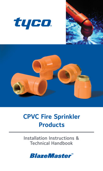
10LISTINGS & APPROVALSof either the minimum flow rates indicated in individual listing or calculatedbased on delivering a minimum of 0.1 gpm/sq.ft. (4,1 mm/min) over thedesign area in accordance with the provisions of NFPA 13:(2007) Section11.3.1.2. Piping shall be mounted directly to the ceiling.- H orizontal Sidewall Sprinklers when the maximum lateral distancebetween sprinklers is 14 ft (4,3 m) or less. Sprinklers shall be Listed200 F (93 C) maximum temperature rated having deflectors located inaccordance with their Listing. The demand for the sprinklers shall be theminimum flow rates indicated in individual listing. Piping shall be mounteddirectly to the side wall.- H orizontal Sidewall Sprinklers when the maximum lateral distancebetween sprinklers exceeds 14 ft (4,3 m) but does not exceed 18 ft(5,5 m). Sprinklers shall be Listed 165 F (74 C) maximum temperaturerated having deflectors 12 in. (305,0 mm) from ceiling and within 6 in.(152,4 mm) of the wall. The demand for the sprinklers shall be the greaterof the minimum flow rates indicated in individual listing or calculatedbased on delivering a minimum of 0.1 gpm/sq.ft (4,1 mm/min) over thedesign area in accordance with the provisions of NFPA 13:(2007) Section11.3.1.2. The maximum sprinkler area of coverage shall not exceed 18 ftx 18 ft (5,5 m x 5,5 m). Piping shall be mounted directly to the side wall.- When applying criteria having a minimum 0.1 gpm/sq.ft (4,1 mm/min),Schedule 80 fittings must be used when sizes are 1-1/2 in. (DN40) andlarger.- Solvent cement joints shall be made with TFP-500 or TFP-600 One StepSolvent Cement.Unfinished Basements - Exposed InstallationsSolid and Composite Wood Joists (UL and C-UL)TYCO CPVC Pipe and Fittings may be installed without protection (exposed)in unfinished basements in accordance with NFPA 13D when subject tothe following additional limitations: The ceiling shall be horizontal and constructed utilizing solid wood joistsor composite wood joists with a nominal depth of 16 in. (406,4 mm) orless on maximum 24 in. (609,6 mm) centers. The distance from the floor to the bottom of the joists shall be between7 ft and 10 ft (2,1 m and 3,0 m). Listed residential pendent sprinklers with a maximum temperature ratingof 155 F (68 C) and a minimum K-factor of 4.9 are to be used for thistype of installation. The maximum sprinkler spacing shall not exceed 16 ft(4,9 m). Lesser areas are also permitted. The system is to be designedbased upon the Listed flows for the sprinkler selected except that the flowfor a single sprinkler or for multiple sprinklers flowing is to be not less than13 gpm (49,2 lpm) per sprinkler. The sprinklers are to be installed with theirdeflectors a maximum of 1-3/4 in. below the bottom of the solid wood orcomposite wood joists in anticipation of future installation of a finishedceiling. (reference NFPA 13D, Section 8.2.4, 2016 Edition) All system mains shall be run perpendicular to the joists. All branch linesshall be run parallel to the joists. Schedule 80 fittings in the 1-1/2 in. andlarger sizes shall be used.
LISTINGS & APPROVALS11 All solvent cement joints shall be made with One Step Solvent Cement(TFP-500 or TFP-600). The maximum length along the joist shall not exceed 40 ft (12,2 m).When the length exceeds 40 ft (12,2 m), blocking shall be utilized.The blocking shall be constructed of minimum 1/2 inch (12,7 mm) plywood,minimum 3/8 in. (9,5 mm) gypsum wallboard or batt insulation with aminimum thickness of 3-1/2 in. (89 mm). These blocking materials shallbe the full depth of the joists. When batt insulation is used as blocking,it must be a single piece of insulation. The insulation must be secured inplace with metal wire netting which must encase the insulation on both of 2the exposed sides. The metal wire netting is required to hold the insulationin place and prevent it from being dislodged or repositioned over time.It is acceptable for items such as piping, wires, ducts, etc. to penetratethe blocking. The gap between the item penetrating the blocking and theblocking should be minimized. For installations where the gap exceeds1/4 inch (6,4 mm), the gap shall be filled with insulation, caulking, or othersuitable material. When installing TYCO CPVC Pipe and Fittings perpendicular (systemmains) to the joists, listed support devices for thermoplastic sprinklerpiping or other listed support devices shall be used which mount thepiping directly to the bottom of the joists. As an alternative to mountingthe pipe and fittings below the joists, it may be acceptable to cut holes inthe joists at or below the center of the depth of the joist for support. Theholes should be oversized to allow for movement and located as to notimpair the structural integrity of the joists.CAUTIONWhen drilling holes in the joists, the structural integrity must be maintained. Consult the authority having jurisdiction (AHJ) or building codefor requirements. When installing TYCO CPVC pipe and fittings parallel (branch lines) to thejoists, the pipe and fittings shall be installed in the cavity below the bottomof the ceiling and above the bottom of the joist. The branch lines shall belocated at or below the center of the depth of the joist. The pipe shall beinstalled utilizing listed support devices for thermoplastic sprinkler pipingor other listed support devices which mount the piping directly to nominal2 in. (50,8 mm) wood blocking or listed support devices for thermoplasticsprinkler piping that offset the pipe a nominal distance of 1-1/2 in.(38,1 mm) from the joists.NOTE:Use of TYCO CPVC pipe and fittings is limited to basements where thequantity and combustibility of contents is low and fires with relativelylow rates of heat release are expected. For additional information regarding the assembly and installation of TYCO CPVC pipe and fittingsrefer to the manufacturer’s installation instructions. The instructions shown here for Unfinished Basements with Exposed SolidWood or Composite Wood Joists require the use of Schedule 80 fittingswhen sizes are 1-1/2 in. (DN40) and larger.
12LISTINGS & APPROVALSFigure 1 - Unfinished Basement, Soild Wood Joists, Center WallRiser with Center Room MainMAIN16'-0"(4,9 m)MAX.8'-0"(2,4 m)MAX.16'-0"(4,9 m)MAX.2x16MAX.24"(609,6 mm)CENTERSBRANCH12" MAX.(304,8 mm)TO CENTEROF RISER1-3/4"(44,5 mm)MAX.8'-0"(2,4 m)MAX.RISER1" MIN.
TYCO CPVC Pipe and Fittings are designed specifically for fire sprinkler systems and provide the following advantages over traditional sprinkler piping systems: Increased hydraulic capabilities (C-Factor 150) No pre-cutting and expensive fabrication required Pipe/Fittings (slip style only) - NSF-pw listed for use in pressure rated