Transcription
Application NoteOutBack Battery SetupUsing OutBack ChargersThis application note will provide some background information on OutBack lead-acid batteries as well asOutBack charging sources and their optimal setup for the most common applications. There are threedifferent types of OutBack lead-acid batteries: Absorbed glass mat (AGM), tubular gel (OPzV) andflooded lead-acid (FLA). These not only have variations in chemical makeup, but their chargingparameters, maintenance and application tradeoffs can also be significantly different. The directionsbelow should be followed carefully with regards to installation, charger programming and maintenance toensure the best possible battery life and safe operation.IntroductionThe main focus of this application note will be on setting up OutBack charging sources for bestoperational performance for both float and cycling applications. However, it’s helpful to understand basicbattery characteristics and other factors that can affect these applications before diving into the details.First, some terminology and quick facts about lead-acid batteries.Days (hours) of Autonomy: number of days (hours) the batteries will run loads without recharging.Cycle: a single discharge and recharge of the batterySoC: state of charge expressed in percent available total capacity.DoD: depth of discharge expressed in percent of total capacity removed.Ambient Battery Temperature: low temperatures reduce capacity, high temperatures reduce cycle life.DoD vs. Cycles: Deeper discharges per cycle reduces battery life. For example, the RE batterydischarged to 20% DoD 3300 cycles, and discharged to 80% DoD 675 cycles.Charge/Discharge Rate: the faster the rate of charge or discharge, the less battery capacity.One common factor in poor battery performance is improper battery sizing for a given systemconfiguration and load use profile. System sizing is a fairly extensive topic of its own and will not bediscussed here in its entirety, but some basic cautions should be understood. A battery bank that isundersized relative to a large photovoltaic (PV) array runs the risk of being overcharged by that PV arrayvia the charge controller unless limits are put onto the array’s output. However, limiting the array’s outputcan curtail some of the PV power at the array as potential energy that never gets converted. Similarovercharging risks are possible with the inverter’s charger as well if not properly constrained, but withoutthe consequence of curtailing potential renewable energy (RE). Oversizing the battery bank relative tothe PV array could run the risk of undercharging the batteries, or over-relying on the inverter’s chargerfrom an AC source using expensive grid or generator power. Undersizing the battery bank relative toload demand could mean a lack of adequate backup power during a grid power outage. These systembehaviors should be carefully considered and factored into an overall system sizing calculation beforepurchasing and setting up the system battery bank. 2018OutBack Power Technologies, Arlington, WA 98223FH‐MM 10/12/2018Page 1 of 10
Application NoteWhen evaluating the battery tradeoffs for your application, consider how often the batteries will bedischarged and how much capacity of the battery will be used for a given discharge cycle. For example,a solar generation application for “selling” back to the grid or self-consumption, plus backup power, willnot need a cycling battery. Also, fewer batteries will be needed since the batteries can be dischargeddeeper. A “float” battery will usually have a lower price, lower self-discharge and up to fifty percent moreyears of life, making the float battery a better choice than a battery designed for high cycle applications.A common battery cycling application is for off-grid applications where the batteries are often dischargedand recharged daily. However, other cycling applications are arising where stored energy is used toreduce or eliminate utility surcharges for high peak demands and time-of-use charges. By going off-gridor self-consuming during these times, expensive surcharges can be avoided. If the batteries are sizedfor these ancillary services as well as backup power for grid loss, then savings from using stored energyto avoid utility surcharges will provide a faster return on investment of a PV generation system, and willprovide the security of backup power for grid loss events.Historically, many off-grid systems were designed for two days of autonomy with depth of dischargelimited to 50%. This might still make sense depending on site location and lifestyle of the occupants, butfor every day of autonomy that is added to the first day, the battery bank will increase in size by the sameamount for each day added. Since batteries are often the most expensive component in the PV system,it might be more economical to enlarge the PV than doubling the size of the battery bank for a secondday of autonomy, or tripling the size for a third day.For a grid connected system, one day of autonomy that matches the sun cycle will be most efficient andcost effective. When sizing the battery bank, be sure to add together the hours per day of ancillaryservices to the 24-hour energy demand of the backup loads. The PV array should also be sized topower loads and charge the batteries at the same time.In addition to float and cycling characteristics, tradeoffs like operating temperature and flooded versussealed batteries will affect price and performance as well, and are summarized below in Table 1.Table 1 - Comparison of OutBack BatteriesSpecVoltsAh @ C100Round Trip EfficiencyFLARENCPLRPLCOPzV2 Vdc & 6 Vdc2 Vdc12 Vdc12 Vdc12 Vdc2 Vdc290 to 1400800 to 2700200200200450 to 300090%95%97%85%95%80%-40 C to 65 C-20 C to 45 20 (@20 C)Float ApplicationsPoorGoodGoodBetterBetterBestCycling ApplicationsBestGoodBetterGoodBestBestShelf Life2 mo.6 mo.6 mo.24 mo.24 mo.6 mo. Operating Temp C-4 C to 49 CCycles @ 50% DoD280018002600Cycles @ 80% DoD1600600FloodedChemistryFloat Life YearsPrice Scale (1-5) 2018-20 C to 50 C -20 C to 60 C -40 C to 45 COutBack Power Technologies, Arlington, WA 98223FH‐MM 10/12/2018Page 2 of 10
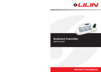
Application NoteIt’s important to note that battery capacity, cycle life, and float life are all influenced by ambienttemperature, charge/discharge rates, and depth of discharge associated with each cycle and cyclingfrequency. Since each site will operate under a unique set of circumstances, there is a high degree ofvariability on what kind of battery performance will be seen over the life of the battery bank for any givensite location and usage case.Also, note that Shelf Life decreases significantly as storage temperature rises. See battery manuals forspecific details on each battery type.VoltageCurrentBattery SOC70% to 90% afterBulk stageSolutionFigure 1 above shows the three charging stages of a lead-acid battery. The first bulk stage is referred toas constant current since the battery cannot support a higher voltage until energy in the form of electricalcurrent restores the battery’s energy capacity. The Bulk stage may start when AC power is lost on theinverter AC input, or when the Re-Bulk voltage setting is reached. It ends when the charging voltagerises to the Absorb voltage which is the point where current starts to drop off from the maximum bulkingcurrent. The battery is about 90% SOC at the beginning of the Absorb stage for an AGM battery, butcould be as little as 70 percent SOC for a flooded lead-acid (FLA) battery. The Absorb stage ends whenthe Absorb timer zeroes out, or if Charge Termination Control is enabled, the Absorb stage is terminatedwhen the OutBack Power FLEXnet DC charge parameters are met (return amps, charge volts and time).The battery is full or 100 percent SOC at the end of the Absorb stage as indicated by the currentreaching a “floor” current known as return amps (a.k.a. end amps). The return amps current is typicallyaround 2-3 percent of the Ah rating of the battery. Once the battery has received an Absorb charge(some battery manufacturers use the term Bulk in place of Absorb) the battery is left in an open-circuit 2018OutBack Power Technologies, Arlington, WA 98223FH‐MM 10/12/2018Page 3 of 10
Application Notestate while the inverter passes through AC power to the loads. When the battery is not charging, then itwill be in a state of self-discharge, even without a connected electrical load. Once the battery isdischarged to a pre-determined state (what OutBack refers to as the Re-Float voltage) then the invertercharger is activated with a charging voltage a few volts lower than the Absorb voltage setting. At theend of a pre-determined Float time, the Float charge is discontinued until the battery once again selfdischarges to the Re-Float voltage and the Float charge stage is repeated.The OutBack charge controller functions similar to the inverter charger in that it has a Bulk/Absorb cycleas well as a Float stage. The charge controller enters a Bulk stage each morning when the solar energyhits the PV array strong enough to “wake” the charge controller. The Bulk/Absorb cycle ends when theAbsorb voltage is met and the Absorb timer zeroes out. Unlike the inverter charger, the chargecontroller does not go “silent” after the Absorb stage, but drops the output to the Float voltage level. It’spresumed if there is PV power available, then it should be utilized for battery charging, load consumption,selling excess power to the grid, or any combination thereof. There is no charge controller Re-Floatsetting since it will always be converting and regulating PV power as long as solar energy is present,unless the batteries are full and there is no AC load demand, in which case it would go silent.For a renewable energy system using both inverters and charge controllers, it is usually preferred tohave the charge controller with priority for charging to save costs over charging from the grid or agenerator. This can be accomplished by setting the charge controller battery charging slightly higherthan the inverter charger settings. The steps for accomplishing this and other charging optimizations arelisted below.OutBack Inverter and Charge Controller Charging Setup Procedure1. Enter the inverter charger settings using the MATE3a. Press the LOCK key and enter the 141 password.b. Press the Settings selection from the Main Menuc. Scroll to and select Inverterd. Scroll to and select Battery Charger and enter the Absorb and Float charging settings listedin Table 1 for the appropriate RE, GH or NC battery type.2. Enter the Charge Controller charger settings using the MATE3a. Press the LOCK key and enter the 141 password.b. Press the Settings selection from the Main Menuc. Scroll to and select Charge Controllerd. Scroll to and select Charger and enter the Absorb and Float charging settings listed in Table1 for the appropriate RE, NC, GH, OPzV or FLA battery type. Set the Absorb and Floatvoltages 0.4 higher (0.2 for 24 Vdc systems) than the inverter settings to give priority chargingto the charge controller. 2018OutBack Power Technologies, Arlington, WA 98223FH‐MM 10/12/2018Page 4 of 10
Application NoteTable 2 - OutBack Inverter and Charge Controller FloatTimeRe-BulkVoltRe-FloatVoltPLC 12V14.1 (56.4) 12 Hours 213.5 (54.4) 1 Abs Time12/24/48 312.5/25/50 3RE 2V2.32 (55.6) 12 Hours 22.25 (54) 1 Abs Time12/24/48 312.5/25/50 3PLR 12V14.7 (58.8) 12 Hours 213.8 (55.2) 1 Abs Time12/24/48 312.5/25/50 3NC 12V14.4 (57.6) 12 Hours 213.6 (54.4) 1 Abs Time12/24/48 312.5/25/50 3OPzV 2V2.45 4 (58.8)2 Hours 52.35 4 (56.4) Abs Time12/24/48 312.5/25/50 37.26 / 2.42 (58)2 hours 26.75 / 2.25 (54) Abs Time12/24/48 312.5/25/50 3FLA 6V / 2VBatteries Supported But No Longer AvailableRE 12V14.4 (57.6) 12 Hours 213.6 (54.4) 1 Abs Time12/24/48 312.5/25/50 3GH 12V14.4 (57.6) 12 Hours 213.6 (54.4) 1 Abs Time12/24/48 312.5/25/50 31If using both inverter and charger controller, set the charge controller 0.4 volts higher (0.2 for 24 Vdc systems)to give the charge controller charging priority.2Will always be 2 hours if charge rate is 10 percent of battery bank amp-hours. For higher or lower chargerates, use the formula AR ½ of charge amps Absorb time, where AR amp-hours remaining after Absorbvoltage is first reached (100% - RT Efficiency x Battery Bank Ah).3Default values for 12/24/48 volt systems. May need to be adjusted for site application.4For operating temperature of 15 to 35 C. See owner’s manual for other temperature ranges.5Two hours maximum per day3. Inverter Settings for Inverter Operating Modesi. Press the LOCK key and enter the 141 password.ii. Press the Settings selection from the Main Menuiii. Scroll to and select Inverteriv. Scroll to and select Grid AC Input Mode and Limitv. Set the Input Mode for desired Offset Mode1. Grid Connected Offset (AC “blending”) modes: Grid Tied, Grid Zero, Supportor Mini Grid2. Off-Grid modes: Backup or GeneratorNOTE: more info on AC input modes can be found in the Radian and FXROperator Manuals and the Offset and AC Input Modes application notes onwww.outbackpower.com 2018OutBack Power Technologies, Arlington, WA 98223FH‐MM 10/12/2018Page 5 of 10
Application Note4. AC Input Charger Limit: An ideal charging current is around 10-13 percent of the Ah rating of thebattery bank, but in some cases this may take longer than desired so a charging current up to themaximum allowed may be used instead. The OutBack inverter charger current limit setting is madefrom the AC input side of the charger, not the DC side of the charger, so the AC charging currentmust be calculated then entered as the charger limit setting.a. First, a conversion of DC charge current to DC watts is made (AC and DC watts are thesame), then charger efficiency applied, then conversion of AC watts to AC current.Using a DC charge current of 40 amps as an example, multiply 40A x 48 Vdc 1920 Wdc 0.85 efficiency 2258 Wac 240 Vac (120 Vac for 120V inverter) 9.4 Aac. Only wholenumbers can be entered so round up or down.b. Enter the inverter charger settings using the MATE3i. Press the LOCK key and enter the 141 password.ii. Press the Settings selection from the Main Menuiii. Scroll to and select Inverteriv. Scroll to and select AC Input and Current Limitv. Scroll to Charger AC Limit and enter the setting5. Charge Controller Current Limitsa. Each charge controller has its own current limit from the maximum setting down to five amps.Typically the charge controller is left to the maximum setting so all available RE is accessibleat all times. If for some reason the maximum current from the charge controller output needsto be limited, it can be changed from the default maximum setting on the MATE3 using thefollowing steps.i. Press the LOCK key and enter the 141 password.ii. Press the Settings selection from the Main Menuiii. Scroll to and select Charge Controlleriv. Scroll to and select Chargerv. Scroll to Current Limit and enter the setting, Leave Absorb End Amps, at 0b. Global Charge Control (GCC) is a MATE3 function that limits the total charge controllercurrent to prevent overcharging of the batteries. For example, if the max charging current fora battery bank is 100A, then max current setting for GCC is also set to 100A. If the inverter iscontributing 50A, then the GCC function in the MATE3 will then limit the total charge controlleroutput to 50A so the total net current to the batteries will be 100A.It's important to note that GCC does not regulate or affect inverter charging at all, it justfactors the inverter current into the equation for total net current to the battery bank.Also important: The GCC uses the charge controller’s Grid Tied function to implement theglobal current control. Therefore, GCC can only be used for Off-Grid applications. Use thefollowing steps to program the MATE3 for Global Charge Control. 2018OutBack Power Technologies, Arlington, WA 98223FH‐MM 10/12/2018Page 6 of 10
Application Notei. Press the LOCK key and enter the 141 password.ii. Press the Settings selection from the Main Menuiii. Scroll to and select MATE3iv. Scroll to and select Global Charger Output Controlv. Change the Enable setting to Y(es), and enter the desired maximum charge amps.OutBack FLEXnet DC Setup Procedure1. The FLEXnet DC (FN-DC) Battery Setup. The FN-DC provides three main functions; data logging ofshunt information including daily kWh, Charge Termination Control and State of Charge (SoC).Charge Termination Control will terminate charging from all OutBack chargers when the BatterySetup settings of Charged Voltage and Time plus the Charged Return Amps that was discussedearlier, are all met. Meeting the Charge Parameters is an indication the battery is full and chargingshould stop. This can save wear and tear on the batteries if for some reason multiple Absorb cyclesare initiated with minimal discharge of the batteries. In this case, the Charge Parameters will mostlikely be met quicker than the Absorb time and can terminate the Absorb stage so the batteries don’tget overcharged. Meeting Charge Parameters will also set SoC to 100 percent. The ChargedVoltage setting is typically 0.2V lower than the lowest charger Absorb voltage setting to ensure theparameter is met in case there is a discrepancy between the charging device voltmeter and theFN-DC voltmeter. The time setting is typically about 3-10 minutes depending on the battery. ReturnAmps is typically 2-3 percent of the battery bank amp-hours, but should be set closer to 3 percent toensure the charge parameters are met.An FN-DC battery function that measures amps in and out of the battery to determine SoC uses thebattery bank amp-hours setting and the Battery Charge Factor (BCF) to determine when the batterybank is full. For example, if the batteries are 90 percent efficient then it would take 100 amps plusanother ten percent (10 amps) to fully recharge a 200 Ah battery bank that had been discharged 50percent. So in this case, the FN-DC would measure 100A on the discharge then 110A on therecharge before indicating the batteries are 100 percent SoC. More information can be found in theFN-DC manual on the OutBack website, as well as an FN-DC application note in the App Notessection of the website.2. The steps for entering FN-DC Battery Setup settings in the MATE3 are show below.a. Press the LOCK key and enter the 141 password.b. Press the Settings selection from the Main Menuc. Scroll to and select Battery Monitor, then select Battery Setupd. Enter the TOTAL battery bank amp-hours in the Battery Ah field.e. Enter the Charged Voltage 0.2 Vdc lower than the lowest Absorb volts setting.f.Enter the time to about 3-10 minutes.3. Enter the Charge Factor as the battery efficiency. This will be 90% for all OutBack AGM batteriesexcept for the NC batteries which should be entered as 95%.NOTE: Charge Termination Control is enabled by default under the MATE3 FN-DC AdvancedControl settings. There is no need to change the setting unless there is a need for it to be disabled. 2018OutBack Power Technologies, Arlington, WA 98223FH‐MM 10/12/2018Page 7 of 10
Application Note4. If the Grid Tied function is being used to sell back to the grid, it’s possible the battery bank may neversee an Absorb stage completed due to the Sell RE setpoint never being exceeded when the chargecontroller is on during the day. So for applications utilizing offset and the Sell RE setpoint, there is afunction under the MATE3 FN-DC Advanced Control settings called Enable Auto Grid-TieControl. Changing from the default of N(o) to Y(es) will disable the Grid Tied mode at midnight andnot re-enable it until the batteries have been allowed to go through an Absorb stage if necessary.Battery Commissioning1. Always measure and record each cell or battery voltage in each string of the battery bank, ortake specific gravity readings for FLA batteries. One or more batteries that are significantly lowerthan the others could indicate a defect battery. See the appropriate battery manual foracceptable levels.2. The voltages measured in step 1 above will determine whether to apply a normal bulk chargeto commission the battery bank, or whether a freshening or equalization charge should beapplied to the battery bank for its initial charge. Consult the appropriate battery manual forspecific initial charging instructions based on the battery voltages, or specific gravitymeasurements for FLA batteries.3. After the initial charge cycle has been completed, it is suggested to load the battery bank with allthe site loads turned on. Then monitor for voltage drops across the batteries, as well as evenbattery voltages and string currents during discharge. If there are bad cabling or bus barconnections, they will show as excessive voltage drops across connecting cables and bus bars.If one of the new batteries is defective, then it will show as a significantly lower voltage thanothers in the string, and a warranty claim should be filed as soon as possible.Tips and Precautions How To Avoid Problems With SoC ReadingsSequential partial charge cycles can lead to erroneous SoC readings since the amps out/amps incounter along with the battery charge factor is only applied when 100 percent SoC is reached.The best way to see if the SoC reading is off is to compare the battery bank voltage with the 100percent SoC reading being displayed. A healthy 48-volt battery bank will read over 51 Vdc at rest(open circuit) when new and fully charged. If the battery bank is over 51 Vdc and the SoCreading is less than 100% (99% is acceptable as it doesn’t actually go to 100% until the batteriesstart to discharge), then cycle the FN-DC power by unplugging the FN-DC cable from theOutBack HUB, wait 20-30 seconds then plug it back in again. If the battery bank is less than51 Vdc, then charge the battery to greater than 51 Vdc (at rest and not rapidly discharging fromthe charge voltage) before cycling the power. This will reset the SoC reading to 100 percent.Both the amps out/amps in counter and the Charge Parameters Met function will reset the SoCreading to 100 percent. The Days Since Charge Parameters Met reading can be viewed tocheck how long it has been since Charge Parameters have been met. This reading can be foundunder the Battery Monitor soft key menu on the MATE3. Press the soft key under thebattery icon on the MATE3 home display (2nd key from left under the display). Then press the Next soft key and Days Since Parameters Met is displayed at the bottom of the screen. 2018OutBack Power Technologies, Arlington, WA 98223FH‐MM 10/12/2018Page 8 of 10
Application Note AC Coupling ApplicationsMany AC Coupling applications are Float applications where a battery based inverter has beenadded to an existing grid-tied inverter (GTI) to provide backup power during a power outage.The PLR batteries are best for this Float application, but some site owners employ AC couplingon a daily basis in either an off-grid application or some kind of ancillary utility service like peakshaving or going off-grid during high time of use charges. For these cycling applications, thePLC, RE, NC or OPzV batteries would be best. However, be aware that any battery in an ACcoupling application will be receiving an unregulated charge when AC coupled and not gridconnected, which is very hard on the batteries and will shorten the battery life. Temperature Corrected ChargingLike many chemical reactions, temperature is also factor in lead-acid battery charging. Attemperatures below 25C, the charging voltage is increased to overcome a less active chemicalreaction at the lower temperatures. At temperatures above 25C, the voltage is reduced toprevent overcharging and permanent damage to the battery. OutBack supplies a remotetemperature sensor (RTS) with all inverters and charge controllers. The lack of an RTS installedin an OutBack system may void the battery warranty, especially when battery charging is doneabove 25C. Only one RTS per system is required, but the deployment of the RTS can varydepending on the both device type and combination of device. It is highly recommended to readand understand the RTS application note in the App Notes section of the OutBack website. 2018OutBack Power Technologies, Arlington, WA 98223FH‐MM 10/12/2018Page 9 of 10
Application NoteAbout OutBack Power TechnologiesOutBack Power Technologies is a leader in advanced energy conversion technology. OutBack products includetrue sine wave inverter/chargers, maximum power point tracking charge controllers, and system communicationcomponents, as well as circuit breakers, batteries, accessories, and assembled systems.Contact InformationAddress:Corporate Headquarters17825 – 59th Avenue N.E.Suite BArlington, WA 98223 USAWebsite:http://www.outbackpower.comEuropean OfficeHansastrasse 8D-91126Schwabach, GermanyOtherOutBack Power Technologies assumes no responsibility or liability for loss or damage, whether direct, indirect,consequential or incidental, which might arise out of the use of this information. Use of this information is entirely atthe user’s risk. OutBack Power Technologies cannot be responsible for system failure, damages, or injury resultingfrom improper installation of their products.Information included in this document is subject to change without notice. 2017 by OutBack Power Technologies. All Rights Reserved. 201810OutBack Power Technologies, Arlington, WA 98223FH‐MM 10/12/2018Page 10 of
Round Trip Efficiency 85% 90% 95% 97% 95% 80% Operating Temp C -4 C to 49 C -20 C to 50 C -20 C to 60 C -40 C to 45 C -40 C to 65 C -20 C to 45 C Cycles @ 50% DoD 2800 1800 2600 1500 3000 3000 . The Bulk stage may start when AC power is lost on the inverter AC input, or when the Re-Bulk voltage setting is reached. It ends when the .


![Smarter Battery Crack [2022-Latest]](/img/13/eliamari.jpg)