Transcription
Stationary Battery SizingIEEE IAS Atlanta ChapterPresented by:Lesley Varga, P.E.Quality Standby Services, LLC1649 Sands Place, SE, Suite CMarietta, GA 30067(770) tystandbyservices.com
Safety First!Basic PPE Personal Protective Equipment –example:– Goggles and face shields, eye protection– Acid-resistance gloves– Protective aprons– Emergency eye-wash and safety showers– Bicarbonate soda and water for neutralization(mixed to the ratio of 1 lb. to 1 gallon)– Insulated tools– Class C fire extinguisher
Personal Protective Equipment
WARNING !!!GAS PRODUCED BY THIS BATTERY CAN BEEXPLOSIVE. PROTECT EYES WHEN AROUNDBATTERY. PROVIDE ADEQUATE VENTILATIONSO HYDROGEN GAS ACCUMULATION IN THEBATTERY AREA DOES NOT EXCEED ONEPERCENT BY VOLUME. DO NOT SMOKE, USEOPEN FLAME OR CREATE SPARKS NEAR THEBATTERY.
WARNING !!!THE BATTERY CONTAINS SULFURIC ACIDWHICH CAN CAUSE SEVERE BURNS. INCASE OF SKIN CONTACT WITHELECTROLYTE, REMOVE CONTAMINATEDCLOTHING AND FLUSH AFFECTED AREASTHOROUGHLY WITH WATER. IF EYECONTACT HAS OCCURRED, FLUSH FOR AMINIMUM OF 15 MINUTES WITH LARGEAMOUNTS OF RUNNING WATER AND SEEKIMMEDIATE MEDICAL ATTENTION.
WARNING !!!SHOCK HAZARD – DO NOT TOUCHUNINSULATED BATTERYCONNECTORS OR TERMINALS. BESURE TO DISCHARGE STATICELECTRICITY FROM TOOLS ANDTECHNICIAN BY TOUCHING AGROUNDED SURFACE IN THEVICINITY OF THE BATTERIES BUTAWAY FROM THE CELLS AND FLAMEARRESTERS.
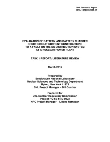
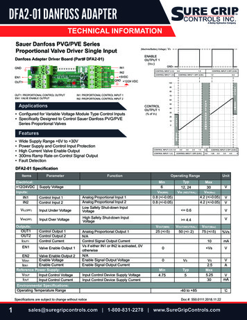
Switchgear and Control DC systemVAC1Φ or 3Φ“125VDC” Bus: 133.8 VDCTypical Float VoltageDC LoadsAC DC24, 48,125 or240 VDC laysBreakerCoilsMotorsPumpsValvesInverterDC AC
System One Line - AC Input LostSwitchgearControlsVAC1Φ or 3ΦDC LoadsAC DC24, 48,125 or240 VDC torsPumpsValvesInverterDC AC
Telecom DC SystemUtilityACInput“48 VDC” Bus: 54.2 VDCTypical Float VoltageAC DCRect. #1Bus WorkPowerBoardTransfer SwAC DCRect. #nBattery GeneratorAC DCRect. #n 1-Distributionto Loads
Telecom DC System -AC Input LostUtilityACInput“48 VDC”: 54.2 VDCTypical Float VoltageAC DCRect. #1Bus WorkPowerBoardTransfer SwAC DCRect. #nBattery GeneratorAC DCRect. #n 1-Distributionto Loads
Telecom DC System – AC Lost,Generator On LineUtilityACInputAC DCRect. #1Bus WorkPowerBoardTransfer SwAC DCRect. #nBattery GeneratorAC DCRect. #n 1-Distributionto Loads
Typical UPS System“480 VDC Bus”: 540 VDC FloatUPSUtilityAC InputRectifierAC DCInverterDC ACTransfer Switch GeneratorBattery-Loads
UPS System –Utility LostBefore GeneratorUPSUtilityAC InputRectifierAC DCInverterDC ACTransfer Switch GeneratorBattery-Loads
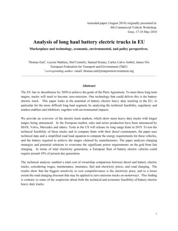
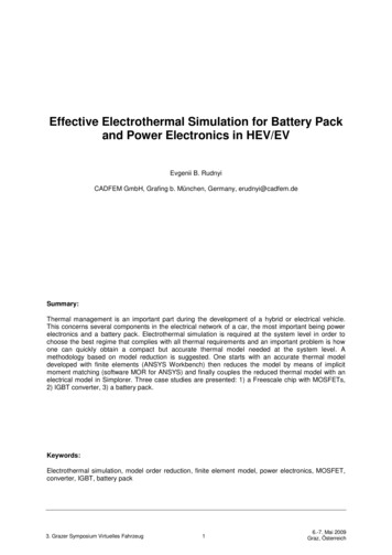
Batteries in Mission Critical ApplicationsFire PumpBatteriesFire PumpUtility ACSubstation Battery125 voltSwitchgear Battery125 V/48 VTelecomEquip48 VDCSwitchgearRectifierEngineStarting Battery24 voltTelecom Battery48 V /24 tteryEmergencyLightingInverterUPS Battery480 Volt 240cellsLOADS
Definition of a Cell Cell: A unit part consisting of twodissimilar electrodes immersed in anelectrolyte;One lead acid cell is 2 volts nominalOne nickel cadmium cell is 1.2 voltsnominal
Definition of a StringString: An energy storage systemconsisting of two or more seriesconnected cells up to the requiredsystem voltageLead Acid“125 Vdc” 58-60 cellsTypical Float 130-134Vdc
Definition of a StringNickel Cadmium“125 Vdc” 90-96 cellsTypical Float 130 -134 Vdc
Battery BasicsWithin the cell the plates are connected in parallel.If each positive plate is 100 Amp Hours in capacity, the cell is 300Amp Hour .2 VoltsSeparatorsPositivePlateNegativePlate
Battery Basics Series connection of Cells– Start with Cell # 1 Positive,connecting from a negativeterminal on cell #1 to a positiveterminal on adjacent cell (typicalconnection within a batterystring)– Add up the cell voltage, but theAmp-hour stays the same– Example: Two 6V-25Ahr unitsconnected in series 12 Volt,25 Amp-hour - - - -Cell #1 .Cell # n
Battery Basics Parallel connection– Connecting from a positiveterminal on one battery to apositive terminal on anotherbattery– Sum the Capacity of each string(Watts or Amp Hours); the voltageremains the same– Example: Two 6V-25 Amp hourunits connected in parallel System: 6 Volts, 50 Amp-hours
Lead Acid Battery Lead dioxide Positive plate,PbO2 Metallic sponge lead Negativeplate, Pb Immersed into an electrolyte ofWater & Sulfuric Acid, H2SO4
Types of Lead Acid Battery Vented Lead Acid (“VLA”)– Also called Flooded or Wet– Lead-Calcium (most common), LeadAntimony, Low Antimony (“lead selenium”)and Pure Lead Valve Regulated Lead Acid (“VRLA”)– Also called Sealed (not maintenance free)– Lead Calcium– Pure Lead– AGM design (Absorbed– Gel designGlass Mat)
Lead Acid Cell rVLA (Flooded)2 Volt VRLA
Lead Acid Grids and PlatesGridPositivePlateNegative Plate
SEPARATORSSeparator: prevents electrical contact between the positive andnegative plates while maintaining sufficient electrolyte to sustaincapacity Flooded: micro porous separator– Grooved design to allow freeliquid and gas movement within cell– Provides prevention from shorts– Glass mat may be used VRLA: “absorbent glass mat” wrapspositive and negative plates– AGM– Gel26
Lead Acid Battery Design DifferencesTelecom BatteryLow Rate/LongDurationUPS BatteryHigh Rate/ShortDurationSwitchgear BatteryGeneral PurposeStep LoadsNominal 8 hr discharge Nominal 15 min.ratedischarge rateCombination of long &short duration ratesThicker pos platesThinner pos platesModerately thick platesPlates farther apartPlates very closeModerate plate centerHigh electrolyte toplate ratioLow electrolyte toplate ratioModerate electrolyte toplate ratioMinimal cyclingImproved cyclingModerate cyclingPoor high ratesVery good high ratesReliable high ratesGood long ratesPoor long ratesReliable long rates
Nickel Cadmium Battery Nickel positive plate Cadmium negative plate Immersed into an electrolyte ofPotassium Hydroxide (alkaline)
Nickel Cadmium Design DifferencesLMHLow rate ofdischargeMediumrate ofdischargeHigh rate ofdischargeCell typeLMHRailwayXXXEmergency aicXXXDiesel startUPSXXXUtility EquipmentXXXEmergency supplyXXXAlarm equipmentX
Nickel Cadmium - Internal ConstructionLLow Rate ofDischargeMMedium Rate ofDischargeHHigh Rate ofDischarge
IEEE Standards, Guides, Practices IEEE Std 485 -2010: Sizing, Stationary Lead AcidIEEE Std 1184-2006: Batteries for UPS SystemsIEEE Std 1189 -2007: Selection & Sizing VRLAIEEE Std 1115-2014: Sizing Nickel CadmiumAdditional System Considerations:1375 – Protection of Battery Systems1578 – Spill Containment1491 – Monitoring Systems1635 – Guide to Ventilation design1657 –Personnel Qualifications for Install & Maint946 – Design of DC Auxiliary Power Systems forGenerating Stations (charger sizing)
General Sizing ConsiderationsThe battery must supply the DC powerwhen:1. The load on the dc system exceeds themaximum output of the charger2. The output of the charger is interrupted3. The AC power is lost (may result ingreater dc power demand than item 2.)
Define the System Loads Continuous – energized throughout the dutycycle Noncontinuous - energized only during aportion of the duty cycle, defined duration Momentary - short duration loads notexceeding 1 minute at any occurrence.– Lead Acid: considered a full minute,1 minute– Nickel Cadmium: for loads 1 sec, consider1 second
Define Load & ApplicationSteady Loads – typically Telecom,“long duration” 8 hour backupsKVA/KW Loads – typically UPS, “highrate, short duration” 15 minutes,KVA/KW ratingsStep Loads –Switchgear & Control –Utility Applications – “step loads” combination of high rates and longduration
Load Classification The loads applied to the battery areeither:– Constant power (inverters, dc/dc powersupplies)– Constant resistance (dc motor starting,relays, contactors, lights)– Constant current (running dc motors) For Sizing purposes, loads are treatedas Constant Power or Constant Current
Selection Factors to be Considered Physical characteristics of the cells Planned life of the installation Frequency and depth of discharge Charging characteristics Maintenance requirements Cell orientation requirements Ventilation requirements Seismic characteristics Spill management
Battery Size – Nominal RatingAmpere-hour: 8 hour capacity of a leadacid storage battery (in the US)– The quantity of electricity that the batterycan deliver in amp-hours at the 8 hour rate.– Example: a “2000 Ampere Hour” batterywill provide 250 amps for 8 hours to 1.75volts per cell(2000/8 250 amps continuously for 8hours) Nickel Cadmium: 5 hour or 10 hour or 20hour rate
Battery Size – Constant PowerRating UPS batteries are rated in Watts or kW– kW/cell x number of cells kWb For a specified time period to a specified endvoltage, e.g.15 minutes to 1.67 volts per cell Battery is typically sized for full load of theUPS system
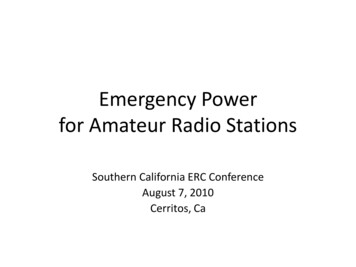
Important Sizing Considerations Operating Temperature– Affects the available capacity– Size for the lowest expectedtemperature– At high temperatures use the ratedcapacity for 77 F– High temperature affects battery life– Cold temperature affects batterycapacity– For Nickel Cadmium- see manufacturer
Temperature Correction Factors From IEEE Std 485-2010
Important Sizing Considerations Aging Margin – LEAD ACID:– Replacement criteria 80% of ratedcapacity.– Battery is defined at end of life at 80%capacity– The initial rated capacity of thebattery should be at least 125 percent(1.25 aging factor) of the loadexpected at the end of its service life.
Important Sizing Considerations Aging – NICKEL CADMIUM:– No defined end of life point– Capacity gradually decreases (linear)– 1.25 margin is typically used– Aging margins of 1.10 – 1.40 may apply
Important Sizing Considerations Initial Capacity– Batteries may have less than ratedcapacity when delivered. Unless 100 %capacity upon delivery is specified, theinitial capacity can be as low as 90% ofrated capacity (per IEEE-485)– Typical UPS and Switchgear batteriesship at 100%; Telecom at 90%
Important Sizing ConsiderationsNickel Cadmium– For the float application (telecom,switchgear, UPS), make sure to usethe data based on Constant PotentialFloat Charging.
Important Sizing Considerations Design margin– It is prudent to provide a capacitymargin to the battery sizing forunforeseen additions to the dc systemand less than optimum operatingconditions.– Typical design margins are 10-15%.
Battery Size Factors governing battery size:– Maximum system voltage– Minimum system voltage– Correction factors (e.g. aging, temperature)– Duty cycle If cells of sufficiently large capacity are notavailable, then two or more strings may beconnected in parallel. The capacity of such abattery is the sum of the capacities of thestrings.
Number of Cells The maximum and minimum allowablesystem voltage (“voltage window”)determines the number of cells in thebattery. When the battery voltage is not allowedto exceed a given maximum systemvoltage the number of cells will belimited by the cell voltage required forsatisfactory charging.
Maximum Voltage48 Volt Telecom ExampleNumber of cells Maximum system voltageMax cell voltage required for chargingGiven:2.33 volts per cell required for equalize chargingMaximum allowable system voltage 56 V and 54 V56 V2.33 Vpc 24 cells54 V2.33 Vpc 23 cells
Minimum VoltageTelecom ExampleMinimum battery voltage equals theminimum system voltage plus the cablevoltage dropMinimum system voltage at the equipment: 42 VDCAllowable voltage drop from battery to load: 2 VDCMinimum battery voltage: (42 2) 44 VDCMinimum battery voltage minimum cell voltageNumber of cellsGiven: the minimum allowable battery voltage is 44 Voltsand the maximum number of cells is 24 or 23:44V 1.83 volts per cell24 cells44V 1.91 volts per cell23 cells
Maximum VoltageSwitchgear ExampleNumber of cells Maximum system voltagecell voltage required for chargingGiven:2.33 volts per cell required for equalize chargingMaximum allowable system voltage either 140 V or 135 V140 V2.33 Vpc 60.08 cells: use 60 cells135V2.33 Vpc 57.94 cells: use 58 cells
Minimum VoltageSwitchgear ExampleMinimum battery voltage equals theminimum system voltage plus the cablevoltage dropMinimum system voltage at the equipment: 103 VDCAllowable voltage drop from battery to load: 2 VDCMinimum battery voltage: (103 2) 105 VDCMinimum battery voltageNumber of cells minimum cell voltageGiven: the minimum allowable battery voltage is 105 Voltsand the maximum number of cells is 60 or 58:105V 1.75 volts per cell60 cells105V 1.81 volts per cell58 cells
Maximum VoltageUPS ExampleNumber of cells Maximum system voltagecell voltage required for chargingGiven:2.38 volts per cell (1.250 sp. gr.) and 2.33 vpc (1.215sp.gr.) required for equalize chargingMaximum allowable system voltage: 576 VDC576 V2.38 Vpc 240 cells576 V2.33 Vpc 247 cells: (typical 240-244 cells)
Minimum Voltage UPS ExampleMinimum battery voltage equals theminimum system voltage plus the cablevoltage dropMinimum system voltage at the UPS equipment: 396 VDCAllowable voltage drop from battery to UPS: 4 VDCMinimum battery voltage: (396 4) 400 VDCMinimum battery voltageNumber of cells minimum cell voltageGiven: the minimum allowable battery voltage is 400 Voltsand the maximum number of cells is 244400V 1.67 volts per cell240 cells400V 1.64 volts per cell244 cells
Sizing Example: Telecom Constant Current loadsSizing for:– Load 400 Amps for 8 hours– 24 cells, battery end voltage 1.75 vpc– Aging margin: 1.25– Design margin: 1.10– Temperature factor at 77 F: 1.00 400 x 1.25 x 1.10 x 1.0 550 Amps continuouslyfor 8 ho
20.04.2015 · UPS Switchgear Switchgear Battery 125 V/48 V Engine Starting Battery 24 volt Rectifier Inverter Telecom Equip 48 VDC Telecom Battery 48 V /24 cells Batteries in Mission Critical Applications Emergency Lighting Emergency Lighting Battery Transfer Switch Fire Pump Fire Pump Batteries Substation Battery 125 volt. Definition of a Cell Cell: A unit part consisting of two dissimilar electrodes .