Transcription
STEEL PLATE SHEAR WALLS (SPSW), TEBF,CFST, SF, AND OTHER SHORT STORIESMICHEL BRUNEAU, Ph.D., P.Eng, F.ASCEDepartment of Civil, Structural, and Environmental EngineeringUniversity at uneau.comMichel Bruneau has conducted research on the evaluation andretrofit of existing steel bridges and buildings subjected todestructive forces, as well as on the development of new designconcepts capable of providing satisfactory seismic-resistance,blast-resistance, or both (as multi-hazard resistant concepts). Hehas conducted reconnaissance visits to numerous disasterstricken areas, is a member of various AISC and CSAspecifications-writing committees, and served as Director of theMultidisciplinary Center for Earthquake Engineering Research.Dr. Bruneau has authored over 400 technical publications, including the textbook “DuctileDesign of Steel Structures,” and two fiction books. He has received many awards for histechnical work (as well as for his latest novel).AbstractThis paper presents brief information summaries on Steel Plate Shear Walls (SPSWs), PerforatedSPSWs (P-SPSWs), Tubular Eccentrically Braced Frames (TEBFs), Concrete Filled Steel Tubes(CFSTs), Structural Fuses (SFs), Rocking Frames (RFs), and Self-Centering SPSWs (SCSPSWs). This paper focuses on the research results of former graduate students with whom theauthor had the pleasure to work1. References are provided for the readers who wish to studyspecific topics in more depth. A broader list of emerging structural systems is available inBruneau et al. (2011).Additional technical information can also be found atwww.michelbruneau.com.NoteFor brevity, hundreds of references to the work of other researchers who contributed to each ofthe topic covered here have been omitted in this paper. Without fault, the reader will find thosecomprehensive citation lists in the literature reviews of the relevant papers cited here.1More specifically for the information presented in this paper, Samer El-Bahey (Stevenson & Associates), JeffreyBerman (University of Washington, Seattle), Daniel Dowden (Ph.D. Candidate, University at Buffalo), ShuichiFujikura (ARUP), Michael Pollino (Case Western Reserve University), Ronny Purba (Ph.D. Candidate, Universityat Buffalo), Bing Qu (California Polytechnic State University), Ramiro Vargas (Technological University ofPanama), Darren Vian (Parsons Brinkerhoff). Not all concepts and systems compatible with the objective of thispaper could be presented here, but the relevant work of other former graduate students can be found on theaforementioned webpage.
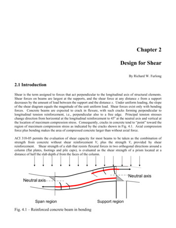
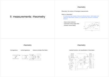
IntroductionNew structural systems and concepts can add to the Structural Engineer’s “toolbox,” providinghim/her with an ever increasing range of solutions to meet increasingly complex designchallenges. In keeping with this analogy, the objective of this paper is to provide an overview ofsome recently developed “tools” that can enrich this toolbox. This objective leads to apresentation that is somewhat unconventional, resulting in a paper that has more breadth thandepth and consisting mainly of brief topic summaries redirected to references to be consulted tofurther explore specific ideas.To limit the scope of this paper, the information presented here only refers to the research resultsof former graduate students with whom the author had the pleasure to work (see list previouspage). As such, focus here is on Steel Plate Shear Walls (SPSWs), Perforated SPSWs (PSPSWs), Tubular Eccentrically Braced Frames (TEBFs), Concrete Filled Steel Tubes (CFSTs),Structural Fuses (SFs), Rocking Frames (RFs), and Self-Centering SPSWs (SC-SPSWs). Abroader list of emerging structural systems, and more comprehensive lists of relevant references,are available elsewhere (Bruneau et al. 2011).Steel Plate Shear Walls (SPSWs)Steel plate shear walls (SPSWs) have been constructed before codified requirements for theirdesign existed. Designed and detailed based on engineering principles, their characteristics haveevolved over time, reflecting improvements in knowledge on this topic as instructed by research.A comprehensive survey of buildings having SPSWs for their lateral load resisting structuralsystem, and of determinant research on that topic at the time, has been presented by Sabelli andBruneau (2007). The number of buildings having SPSWs and of research projects studying thatstructural system has increased substantially since it has been introduced in design specifications(CSA 1994, 2001, 2009; AISC 2005, 2010).For multistory SPSWs, plastic analysis can be used to predict ultimate capacity. The desirableplastic mechanism involves uniform yielding of the plates over every story (Figure 1b). Thecorresponding ultimate strength of SPSW having rigid beam-to-column connections capable ofdeveloping the beam’s plastic moment, calculated by the kinematic approach, is:nsnsns1(1) i Vi hi i 2 Fy (t i t i 1 )Lhi sin 2α i 2M pbiwhere hi is the ith story elevation, Vi and ti are respectively the applied lateral load and thethickness of the plate at that story, ns is the total number of stories, and Mpbi is the plasticmoment of the ith story beam (identical plastic hinge strengths are assumed at both HBE endshere – the equation can be modified if not the case). Derivation of these equations is presented inBerman and Bruneau (2003a), as well as for the soft-story case of Fig 1a. The mechanism in Fig1b also provides useful information for capacity design principles.The design philosophy for SPSW clearly states that the infill plates are intended to be the energydissipating element. With the exception of plastic hinges at the end of the beams (calledHorizontal Boundary Elements (HBEs)) and at the base of columns (called Vertical BoundaryElement (VBEs)), the HBEs and VBEs are to remain elastic. Commentary material in early
specifications provided alternative methods to calculate forces in VBE, but some of thesemethods were demonstrated to lead to incorrect results and subsequently deleted in AISC 34110. The systematic free-body-diagram approach proposed by Berman and Bruneau (2008a) hasbeen shown to better match results from push-over analysis.(a)(b)Figure 1. SPSW Plastic Mechanisms (Berman and Bruneau 2003b, Courtesy of MCEER, University at Buffalo): (a)Soft-Story Mechanism; (b) Uniform Yielding MechanismVBE design is also currently subjected to flexibility limits. After SPSW specimens by Lubell, etal. (2000) exhibited significant "pull-in" deformation or undesirable premature out-of-planebuckling, Montgomery and Medhekar (2001) ascribed this poor performance to insufficient VBEstiffness, on the rationale that if VBEs deform excessively, they may be unable to anchor theinfill panel yield forces. For that reason (as well as to ensure uniform yielding of the infill plate),CSA S16-01 introduced the flexibility factor, ωt , proposed in previous analytical work of plategirder theory (Wagner 1931, Kuhn et al. 1952 – summarized in Qu and Bruneau 2008, 2010b), asan index of VBE flexibility, defined as:tωt 0.7 hsi 4 wi(2)2Ic Lwhere twi is the web plate thickness, L and hsi are the width and height of the SPSW panel, and Icis the inertia of a VBE adjacent to the panel. Noting that the Lubell et al. specimens hadflexibility factors of 3.35, and that all other known tested SPSWs that behaved in a ductilemanner had flexibility factors of 2.5 or less, CSA S16-01 empirically specified an upper bound
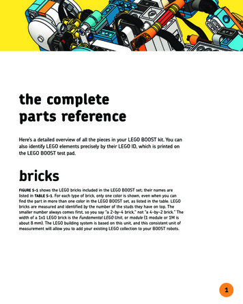
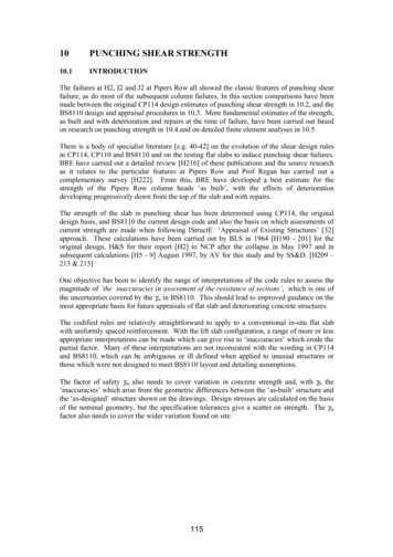
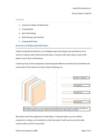
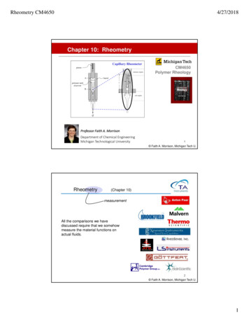
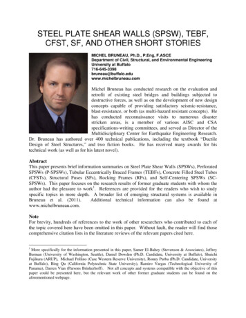
of 2.5 on ωt . With that upper bound of 2.5 on Equation 2 and solving for I c leads to thefollowing requirement, first implemented in CSA S16-01, and subsequently AISC 341:0.00307twi hsi 4Ic (3)LHowever, Qu and Bruneau (2008, 2010b) found that, for seismic design, this existing limit isuncorrelated to satisfactory in-plane and out-of-plane VBE performance, and that the significantinward inelastic deformations of VBEs observed in past tests were not directly caused byexcessive VBE flexibilities but rather due to shear yielding at the ends of VBEs. Significantly,the data presented by Qu and Bruneau included a test by Lee and Tsai (2008) having ωt 3.0,with adequate VBE shear strength and exhibiting satisfactory behavior.As a result, both AISC 341-10 and CSA-S16-09 indicate that shear yielding may be a governinglimit state in VBEs. Accounting for shear, axial, and flexure interaction is recommended forVBE design to ensure elastic response. In future editions of the seismic provisions, theflexibility limit may either disappear or be kept for other reasons.As far as HBE design is concerned, HBE stiffness impacts the progression of yielding in webplates. Using a strip model, Bruneau and Bhagwagar (2002) showed that, at the extreme, forinfinitely elastic HBEs and VBEs of low stiffness in SPSWs having large panel aspect ratios, L/h,some strips may even end-up in compression because of HBE deflections induced by other stripsin tension. However, such an extreme response is unlikely in actual designs, given that HBEstiffness is related to strength. Rather, progressive yielding across the width of a given web plateis typically observed upon increasing SPSW drift, as shown in Figure 2c for the first story webplates of specimens tested by Driver (1997) and Lee and Tsai (2008) and having substantiallydifferent boundary frame flexibility. This progression of yielding is also exhibited in the pushover curves, such as those shown in Figure 2a. HBE stiffness should be adequate to achievedevelopment of the web plates’ full yield strength at the design drift. Note that infinitely rigidpin-ended HBEs and VBEs would be required to achieve simultaneous yielding of all stripsacross a web plate.Strengthwise, HBEs are simultaneously subjected to flexural moments, shear and axial forces. Inaddition, when shear stresses and axial stresses perpendicular to the HBE’s longitudinal axis aresignificant in the webs of HBEs, this should also be taken into account in the interactionequations. A procedure to account for these effects in calculating plastic hinge strength has beenproposed by Qu and Bruneau (2010a, 2011).HBEs should also be designed such that their plastic strength is not reached at any point alongtheir length, except at their ends. Vian and Bruneau (2005), using the equilibrium method,demonstrated that HBEs must be designed to resist ωL2/4 to prevent in-span hinges, as illustratedin Figure 3. Purba and Bruneau (2010, 2012) demonstrated that plastification along HBE spanscan induce significant (and possibly excessive) accumulation of plastic incremental deformationson the HBEs, themselves leading to only partial yielding of the infill plates and correspondinglylower global plastic strength compared to the values predicted by code equations. Samplenonlinear time history analysis results for SPSWs having HBEs designed to prevent in-spanhinging (SPSW-CD case) or not (SPSW-ID case) are compared in Figure 4.
1.2σ / fy1.0E 0068.0E 0050.80.60.40.26.0E 0050.01.24.0E 0052.0E 0050.0E 000Specimen: Two-story SPSW (SPSW S)Flexibility factor: ωt 3.01Researchers: Tsai and Lee (2007)1F Drift 0.2%1.0σ / fyBase Shear (N)1F Drift 0.1%1.01.2E 0063.5E 0060.80.60.41.22.0E 0061.01.5E 0061.0E 0065.0E 005Specimen: Four-story SPSWFlexibility factor: ωt 1.73Researcher: Driver (1997)σ / fy0.02.5E 0060.80.60.40.00.0E 0001.20.0 0.5 1.0 1.5 2.0 2.5 3.0 3.5 4.0 4.5 5.0 5.51F Drift (%)1F Drift 0.6%1.0σ / fy(a)1F Drift 0.3%0.20.80.60.40.20.01.21F Drift 2.0%1.0oσ / fyBase Shear (N)0.23.0E 0060.80.60.40.2lαLee and Tsai (2008)Driver (1997)0.00.0 0.1 0.2 0.3 0.4 0.5 0.6 0.7 0.8 0.9 1.0x/lαx(c)(b)Figure 2 Uniformity of Tension Fields (a) Pushover Curves, (b) Schematic of Tension Fields, (c)Uniformity of Panel Stresses (Qu and Bruneau 2008, Courtesy of MCEER, University at Buffalo)
2.0κ 0.0κ 0.5κ 1.0κ 1.5κ 2.0MaximumNormalized Moment: M(x) / .50.60.7Fraction of span from left support0.80.91Figure 3 Normalized moment diagram for end-moment values of 0, ½, 1, 1½, and 2 times the hanging moment ωL2 /8 (Vian and Bruneau 2005, Courtesy of MCEER, University at Buffalo)Figure 4 Time history of in-span vertical displacement of HBE (Purba and Bruneau 2010, Courtesy of MCEER,University at Buffalo)Perforated SPSWs (P-SPSWs)For low-rise buildings, the SPSW web thicknesses required to resist specified lateral loads areoften less than the minimum panel thickness available from steel producers for hot rolled plategrades. In such cases, use of the minimum available thickness may result in large panel forceoverstrengths and, as a consequence of the capacity design principles, substantially larger HBEsand VBEs (and foundations) than would otherwise be necessary if the exact required webthickness was used. Furthermore, use of identical plate thicknesses along the building heightincreases the risk of developing a soft-story mechanism. One approach to alleviate this problemis to use light-gauge cold-formed steel plates (Berman and Bruneau 2003b, 2005), but theproperties of such material can be quite variable, and axial-testing of coupons from the actualplates to be used in a given SPSW are recommended to verify design/ductility assumptions.
Another viable approach is to use low-yield steel, taking into account the strain hardenedstrength of that steel at the maximum drift (Vian and Bruneau 2005, Vian et al. 2009a, 2009b).A better approach (in AISC 341-10 and CSA S16-09) consists of using SPSWs having a specialpanel perforations layout covering the entire web plate in a specified regular pattern selected toreduce the strength and stiffness of a solid panel wall to the levels required by design. A typicallayout forcing tension strips to develop at 45 degrees is shown in Figure 5. Such specialperforated SPSW exhibited stable force-displacement behavior and hysteretic behavior duringtesting (Vian and Bruneau 2005, Vian et al. 2009a). Note that the multiple holes can beconvenient for utility lines and cables to pass through the web, but a special reinforced cornercutouts detail may be more effective for that specific purpose (Vian and Bruneau 2005).Figure 5 Perforated Steel Plate Shear Walls (Vian and Bruneau2005, Courtesy of MCEER, University at Buffalo)Purba and Bruneau (2007, 2009) investigated panel strain and stress behavior for a range of holegeometries that led to proposed design recommendations for limiting perforation sizes tofacilitate ductile response. Figure 6 presents web plate strength ratios (Vyp.perf/Vyp) versusperforation ratios (D/Sdiag) for frame drifts (γ) of 1, 2, 3, 4 and 5%, where Vyp,perf and Vyp are thestrength of the perforated and solid plates, respectively, and shows the linear regression analysisof the results that led to the following design equation for the strength of the perforated web plate,adopted by AISC 341-10 and CSA S16-09: D V yp. perf 1 0.7 V yp(4)S diag for perforation ratio limited to D/Sdiag 0.6, where D is the perforation diameter, and Sdiag is thediagonal strip spacing measured perpendicularly to the strip. Figure 7 illustrates how frame driftcorrelates to the corresponding local maximum strain in the web plate for the system considered,for various given perforation ratios. Vian and Bruneau (2005) also provided an equation for thereduction in panel stiffness due to the presence of perforations.
3000Total Shear Strength, V y (kN)25002000emax 20%emax 15%emax 10%emax 5%emax 1%SolidD050 (D/Sdiag 0.12)D100 (D/Sdiag 0.24)D150 (D/Sdiag 0.35)D200 (D/Sdiag 0.47)D250 (D/Sdiag 0.59)D300 (D/Sdiag 0.71)Bare1500100050000.01.02.03.04.05.0Frame Drif, γFigure 6 Web Plate Strength Ratios (Vyp.perf/Vyp)versus Perforation Ratio (D/Sdiag) (Purba andBruneau 2007, Courtesy of MCEER, University atBuffalo)Figure 7 Total Shear Strength Vy versus Frame Driftγ (Purba and Bruneau 2007, Courtesy of MCEER,University at Buffalo)Tubular Eccentrically Braced Frames (TEBFs)All of the original research on EBF was conducted for frames with W-shape beams, and lateralbracing had to be provided at the ends of these links to ensure their stability during large inelasticdeformations. However, in some applications, eccentrically braced frames would be desirable inlocations where lateral bracing of the link cannot be achieved. In such cases, links with built-upbox sections can be used, because such built-up box cross-sections are not susceptible to lateraltorsional buckling. Eccentrically braced frames having such links and without lateral bracing ofthe link beam have performed in a ductile manner during experiment, provided that specifiedsection compactness requirements are met (Berman and Bruneau 2007, 2008b, 2008c). Note thatHSS sections cannot be used for such links, due to concerns about their low cycle fatigue lifeunder large inelastic deformations (see Bruneau et al. 2011). Also note that extremely tall andnarrow boxes may not be adequate either, as they can experience lateral-torsional buckling (i.e.,buckle about their weak axis); to prevent this undesirable behavior, links of built-up box sectionsshould be sized such that Iy 0.67Ix, where Iy, is the link’s moment of inertia about an axis in theplane of the EBF, and Ix is the moment of inertia about an axis perpendicular to that plane.External intermediate stiffeners, as in Figure 8, were considered in the experimental andanalytical work of Berman and Bruneau (2006; 2008b; 2008c); these were welded to both thewebs and the flanges. However, because such stiffeners have no benefit on flange buckling,AISC 341 and CSA S16 do not require them to be connected to the flange. This suggests thatintermediate stiffeners could be fabricated inside the built-up box section (which may bedesirable for architectural appeal or other reasons).
(a)(b)Figure 8 (a) Generic built-up box cross-section with exterior stiffeners; (b) Deformed Link at 0.123 rads Rotation(Berman and Bruneau 2005; Courtesy of MCEER, University at Buffalo)Note that EBF having built-up box links have been usedfor the towers of the temporary structure designed tosupport and provide seismic resistance to the deck of theself-anchored suspension segment of the East Span of theSan-Francisco-Oakland Bay Bridge during itsconstruction (Figure 9).Concrete Filled Steel Tubes (CFSTs)The recognized ductile behavior of concrete-filled steeltubes (CFSTs) already makes them desirable for seismicapplications. However, with the emerging desire to usestructural systems able to exhibit satisfactoryperformance under multiple hazards (Bruneau 2007), andgiven that design to resist one hazard does notautomatically provide resistance against another hazard,CFSTs are attractive to provide protection againstcollapse under both seismic and blast loading.Figure 9 EBF tower for temporary supportstructure of new self-anchored suspensionBay Bridge (Courtesy of Klohn CrippenBerger)This structural configuration was therefore selected forexperimental verification of its blast resistance – seismicperformance of such columns had already beendemonstrated by researchers, such as Marson and Bruneau (2004). A series of blast experimentson 1/4 scale multi-hazard bridge piers was performed by Fujikura et al. (2007, 2008). Piers wereCFST columns with different diameters [D 102 mm (4”), 127 mm (5”) and 152 mm (6”)],connected to a steel beams embedded in the cap-beam and a foundation beam. The bent framewas braced in what would correspond to the bridge longitudinal direction at the level of the capbeams. A reaction frame was built for this purpose. Blast tests showed that CFST columns ofbridge pier specimens exhibited a satisfactory ductile behavior under blast loading as shown in
Figure 10a. The foundation connection concept applied in this experiment allowed to developthe composite strength of the CFST columns under blast loading.Note that for comparison,another test series wasconducted to examine theblast resistance of ductilereinforced concrete bridgepiers [D 203 mm (8”)]and non-ductile RC bridgepiers retrofitted with steeljackets [D 213 mm (83/8”)] designed accordingto the current seismicknowledge and detailingprovision, as applied intypical highway bridgedesigns. Out of that testseries, standard RC and(a)(b)steel jacketed RC columnsFigure10(a)CFSTcolumn(D 127mm)afterthetest;(b)RC column afterwere not found to exhibitsmaller blast charge test (Fujikura and Bruneau 2007 and 2008; Courtesy ofa ductile behavior underMCEER, University at Buffalo)blast loading, failing indirect shear at their base rather than by flexural yielding as was the case with CFST columns (e.g.as in Figure 10-b). Furthermore, this non-ductile failure occurred for a much smaller blastpressure than used for the comparable CFST (Fujikura and Bruneau 2008, 2011, 2012).Reinforced concrete details by current seismic codes and steel jacketing, known to be effective toprovide satisfactory seismic performance, were thus shown to be ineffective for the blast loadingcases considered. On-going research is investigating the benefits of using Concrete FilledDouble Skinned Tubes (CFDSTs as another promising alternative (Fouche and Bruneau 2010).VStructural Fuses (SFs)TotalVpWhile the term structural fusehas been used extensively in theliterature, in a true structural fuseanalogy, all damage shouldconcentrate on disposable andeasy to repair structural elements(i.e., “structural fuses”), whilethe main structure is designed toremain elastic (or, at worse, withminor inelastic deformations).Following a severe damagingearthquake, only these specialelements would need to beαK1 KfVyK1Structural FusesVydVyfKaΔyaFrameKfΔyfuFigure 11 Sample model of a SDOF system with metallic fuses, andgeneral pushover curve (Vargas and Bruneau 2006a; Courtesy ofMCEER, University at Buffalo)
replaced (hence, the “fuse” analogy), making repair works easier and more expedient.Furthermore, in that instance, self-recentering of the structure would occur once the ductile fusedevices are removed, i.e., the elastic structure would return to its original undeformed position.This structural fuse definition is conceptually illustrated in Figure 11 using a general pushovercurve for a frame having metallic fuses, represented by elasto-plastic springs acting in parallel.The total curve is tri-linear with the initial stiffness, K1, calculated by adding the stiffness of theframe and the structural fuses, Kf and Ka, respectively. Once the structural fuses reach their yielddeformation, Δya, the increment on the lateral force is resisted only by the bare frame, being thesecond slope of the total curve equal to the frame stiffness, Kf. Vyf and Vyd are the base shearcapacity of the bare frame and the structural fuses, respectively; and Vy and Vp are the totalsystem yield strength and base shear capacity, respectively. If system response is maintained toless than Δyf, replacement of the fuse can be achieved with relative ease (as experimentallydemonstrated in shake-table tests by Vargas and Bruneau (2006b, 2009) for a three story frameusing Buckling Restrained Braces as Structural Fuses). Note that exceeding Δyf is not fatal interms of life safety when using a relatively ductile “protected” frame; rather, it implies that selfcentering upon replacement of the fuse may not occur, and the possible need for repair of theframe.Figure 12 shows a proposed twin column segmental bridge bent implementing SPSLs and BRBsas a series of structural fuses between the columns (2/3 scale specimen). The columns used forthe experiment consisted of segments of Bi-Steel sections (Boweman et al 1999).(a)(b)(c)Figure 12 Experiment setup of Structural Fuse Bent (a) with Special Plate Fuses; (b) with Buckling Restrained BraceFuses; (c) Test Set-up (El-Bahey and Bruneau 2010; Courtesy of MCEER, University at Buffalo)All specimens tested in this experimental program exhibited stable force-displacement behavior,with little pinching of hysteresis loops until the significant accumulation of damage at large drifts.All specimens performed well, behaving elastically at small displacements and exhibiting stablehysteretic behavior as the seismic energy was dissipated through the structural fuses. Adding thefuses increased both the stiffness and strength of the bare frame about 40% and increased theamount of energy dissipated by the frame (El-Bahey and Bruneau 2012a, 2012b).
Rocking Frames (RFs)Rocking here refers to the temporary uplifting of an element from its base (or the element belowit) in an overturning motion. A considerable body of literature exists on the rocking response ofvarious types of rigid or flexible structures and structural elements during earthquake excitations,and a few bridges currently exist in which rocking of the piers during earthquakes has beenallowed to achieve satisfactory seismic resistance.PED DeviceRetrofitted Pier(a)(b)Figure 13 Rocking of bridge tower: (a) Schematic and location of energy dissipation device adjacent to columns freeto uplift, and; (b) Hysteretic behavior (Pollino and Bruneau 2004, Courtesy of MCEER, University at Buffalo).The hysteretic curves obtained from a controlled-rocking system are “flag-shaped” as shown in(Figure 13) for the case of a 2-legged bridge pier free to rock and having BRBs at their base toprovide energy dissipation; the BRBs are considered here to behave elasto-plastically and areassumed to be implemented vertically such that they do not transfer horizontal shear at the baseof the pier. Equations for this behavior are derived in Pollino and Bruneau (2007). Rockingbehavior can also be captured in a structural model by inserting gap elements at the rockinginterface (available in most structural analysis programs), in parallel to yielding elements in thecase of controlled rocking.A 1/5-length scale, four-legged bridge pier specimen, using various passive devices to controlrocking, performed satisfactorily when subjected to three components of seismic ground motionsduring shake table testing. The specimen was not damaged and recentered following each test.This experimental program also demonstrated the adequacy of proposed design equations andanalytical models (Pollino and Bruneau 2010a, 2010b).Self-Centering SPSWs (SC-SPSWs)Many researchers have shown that post-tension (PT) rocking moment connections can be used toprovide moment-frame self-centering capability and to limit hysteretic damage to replaceableenergy dissipating elements during earthquakes. Validation of performance for systems havingthis alternative type of moment resisting frame connection has been established based on
analytical and experimental research and shows that these types of systems could be a viablealternative to conventional LFRS systems. Building on this idea, research is being conducted toinvestigate the potential of achieving Self-Centering Steel Plate Shear Walls (SC-SPSW) byusing similar post-tensioned rocking beam connections (Berman et al. 2010, Clayton et al. 2012,Dowden et al. 2012). In this proposed system, the SC-SPSW web plate is the replaceable energydissipation element, and beam-plastic hinging is eliminated. The system combines theadvantages of high lateral stiffness, a substantial energy dissipation capacity, and self-centeringcapability, at the expense of additional challenges to understanding the flow of forces within thestructure compared to conventional SPSW (themselves, more complex than moment frames).Experimental testing of one-third scale single-bay three-story test specimens are currentlyunderway at the University at Buffalo to investigate the system performance of SC-SPSWs(complementarily to tests previously conducted at the University of Washington, Seattle, as partof a collaborative research effort). The full experimental program consists of quasi-static andshake-table testing to investigate SC-SPSW system performance with three different rockingjoint configurations. The test specimen and setup is shown in Figure 14. Testing will be done onspecimens with HBEs rocking; as well as for a proposed centerline rocking detail and the NewZBREAKSS connection developed to eliminate frame expansion during rocking (Dowden andBruneau 2011).(a) Test Frame Before Whitewash(b) Test Set-UpFigure 14 UB Test Specimen – Photos by Dan DowdenAcknowledgmentsThis work presented here was supported in part by various grants from the National ScienceFoundation (EERC and NEES Programs), New York State, the Federal Highway Administration,the American Institute of Steel Construction, the Engineer Research and Development Center(ERDC) of the U.S. Army Corps of Engineers, MCEER, NCREE, Star Seismic, and Corus Steel.This support is sincerely appreciated. However, any opinions, findings, conclusions, andrecommendations presented in this paper are those of the writer and do not necessarily reflect theviews of the sponsors.
ReferencesComprehensive citations of the work of other researchers who contributed to each of the topic covered in this paperare included in some of the papers listed below.1. AISC. (2005). “Seismic Provisions for Structural Steel Buildings,” ANSI/AISC 341-05, American Instituteof Steel Construction Inc., Chicago.2. AISC. (2010). “Seismic Provisions for Structural Steel Buildings,” ANSI/AISC 341-10, American Instituteof Steel Construction Inc., Chicago.3. Berman, J.W. and Bruneau, M. (2003a). “Plastic Analysis and Design of Steel Plate Shear Walls,” Journalof Structural Engineering, ASCE, 129(11), pp 1448-1456.4. Berman, J., Bruneau, M., (2003b). “Experimental Investigation of Light-Gauge Steel Plate Shear Walls forthe Seismic Retrofit of Buildings”, Technical Report MCEER-03-0001, Multidisciplinary Center forEarthquake Engineering Research, State University of New York at Buffalo, Buffalo, NY, 2003, 163 pages.5. Berman, J., Bruneau, M., (2006). “Further Development of Tubular Eccentrically Braced Frame Links forthe Seismic Retrofit of Braced Steel Truss Bridge Piers”, Technical Report MCEER-06-0006,Multidisciplinary Center f
As a result, both AISC 341-10 and CSA-S16-09 indicate that shear yielding may be a governing limit state in VBEs. Accounting for shear, axial, and flexure interaction is recommended for VBE design to ensure elastic response. In future editions of the seismic provisions, the flexibility