Transcription
SMT IPMIUser's GuideRevision 2.0a
The information in this User’s Manual has been carefully reviewed and is believed to be accurate.The vendor assumes no responsibility for any inaccuracies that may be contained in this document,and makes no commitment to update or to keep current the information in this manual, or to notifyany person or organization of the updates. Please Note: For the most up-to-date version ofthis manual, please see our web site at www.supermicro.com.Super Micro Computer, Inc. ("Supermicro") reserves the right to make changes to the productdescribed in this manual at any time and without notice. This product, including software and documentation, is the property of Supermicro and/or its licensors, and is supplied only under a license.Any use or reproduction of this product is not allowed, except as expressly permitted by the termsof said license.IN NO EVENT WILL SUPER MICRO COMPUTER, INC. BE LIABLE FOR DIRECT, INDIRECT,SPECIAL, INCIDENTAL, SPECULATIVE OR CONSEQUENTIAL DAMAGES ARISING FROM THEUSE OR INABILITY TO USE THIS PRODUCT OR DOCUMENTATION, EVEN IF ADVISED OFTHE POSSIBILITY OF SUCH DAMAGES. IN PARTICULAR, SUPER MICRO COMPUTER, INC.SHALL NOT HAVE LIABILITY FOR ANY HARDWARE, SOFTWARE, OR DATA STORED OR USEDWITH THE PRODUCT, INCLUDING THE COSTS OF REPAIRING, REPLACING, INTEGRATING,INSTALLING OR RECOVERING SUCH HARDWARE, SOFTWARE, OR DATA.Any disputes arising between manufacturer and customer shall be governed by the laws of SantaClara County in the State of California, USA. The State of California, County of Santa Clara shallbe the exclusive venue for the resolution of any such disputes. Supermicro's total liability for allclaims will not exceed the price paid for the hardware product.FCC Statement: Refer to Supermicro's web site for FCC Compliance Information.California Best Management Practices Regulations for Perchlorate Materials: This Perchloratewarning applies only to products containing CR (Manganese Dioxide) Lithium coin cells. “PerchlorateMaterial-special handling may apply. See ING: Handling of lead solder materials used in thisproduct may expose you to lead, a chemical known tothe State of California to cause birth defects and otherreproductive harm.Manual Revision 2.0aRelease Date: March 4, 2011Unless you request and receive written permission from Super Micro Computer, Inc., you may notcopy any part of this document.Information in this document is subject to change without notice. Other products and companiesreferred to herein are trademarks or registered trademarks of their respective companies or markholders.Copyright 2011 by Super Micro Computer, Inc.All rights reserved.Printed in the United States of America
PrefacePrefaceAbout this User's GuideThis user guide is written for system integrators, PC technicians andknowledgeable PC users who intend to configure the IPMI settings supported bythe Nuvoton WPCM450 BMC Controller embedded in Supermicro's motherboards.It provides detailed information on how to configure the IPMI settings supported bythe WPCM450 Controller.Note: Nuvoton Technology is a subsidiary of Winbond Corp.User's Guide OrganizationChapter 1 provides an overview on the Nuvoton WPCM450 Controller. It alsointroduces the features and the functionality of IPMI.Chapter 2 provides detailed instructions on how to configure the IPMI settingssupported by the WPCM450 Controller.Chapter 3 provides the answers to frequently asked questions.Conventions Used in This User's GuidePay special attention to the following symbols for proper IPMI configuration.Warning: Important information given to avoid IPMI configuration errors,Note: Additional information given to ensure correct IPMI configurationsetup.iii
SMT IPMI User's GuideContacting SupermicroHeadquartersAddress:Tel:Fax:Email:Web ss:Super Micro Computer, Inc.980 Rock Ave.San Jose, CA 95131 U.S.A. 1 (408) 503-8000 1 (408) 503-8008marketing@supermicro.com (General Information)support@supermicro.com (Technical Support)www.supermicro.comSuper Micro Computer B.V.Het Sterrenbeeld 28, 5215 ML's-Hertogenbosch, The Netherlands 31 (0) 73-6400390 31 (0) 73-6416525sales@supermicro.nl (General Information)support@supermicro.nl (Technical Support)rma@supermicro.nl (Customer Support)Super Micro Computer, Inc.4F, No. 232-1, Liancheng Rd.Chung-Ho 235, Taipei CountyTaiwan, R.O.C. 886-(2) 8226-3990 886-(2) 8226-3991www.supermicro.com.twTel:Fax:Web Site:Technical 228-1366, ext.132 or 139iv
PrefaceNotesv
SMT IPMI User's GuideTable of ContentsPrefaceChapter 1 Introduction1-1Overview of the Nuvoton WPCM 450 BMC Controller . 1-1WPCM450 DDR2 Memory Interface . 1-1WPCM450 PCI System Interface. 1-1Supermicro IPMI Features . 1-21-2WPCM450 Block Diagram . 1-31-3Introduction to the IPMI Platform . 1-31-4Motherboards Supported . 1-41-5An Important Note to the User . 1-4Chapter 2 Configuring the IPMI Settings2-1Configuring BIOS . 2-12-2Configuring the IP/MAC Addresses for Remote Servers . 2-3Using the IPMICFG Utility to Set the IP/MAC Addresses for Remote Servers . 2-32-3Connecting to the Remote Server . 2-5Using the IPMIView to Connect to the Remote Server . 2-5Using the Browser to Connect to the Remote Server . 2-52-4Accessing the Remote Server via Console Redirection Using the Browser . 2-6To Log In to the Remote Console . 2-62.5IPMI Main Screen . 2-72.6System Status . 2-82.7Server Health . 2-92.7.1 Sensor Readings . 2-102.7.2 Event Log . 2-122.8Configuration . 2-132.8.1 Configuring the Alerts Settings . 2-142.8.2 Configuring Date and Time Settings . 2-162.8.3 Configuring the Light-Weight Directory Access Protocol (LDAP) Settings . 2-172.8.4 Active Directory Settings . 2-182.8.5 Configuring the Radius Settings . 2-202.8.6 Configuring the Mouse Mode Settings . 2-212.8.7 Configuring Network Settings . 2-222.8.8 Configuring Dynamic DNS (Domain Name System) Settings . 2-242.8.9 Configuring the Remote Session Settings . 2-25vi
Table of Contents2.8.10 Configuring the SMTP Settings . 2-262.8.11 Configuring the SSL (Secure Sockets Layer) Certification . 2-272.8.12 Configuring Users Settings . 2-282.9Remote Control . 2-302.9.1 Launching Console Redirection . 2-312.9.2 Remote Control - Server Power Control. 2-522.9.3 Remote Control-Launch SOL. 2-532.10Virtual Media . 2-552.10.1 Configuring USB Floppy & Flash Device Settings . 2-562.10.2 Configuring CD ROM Image File Settings. 2-572.11Maintenance . 2-592.11.1 Maintenance - Firmware Update. 2-602.11.2 Maintenance - Unit Reset . 2-622.11.3 Maintenance - IKVM Reset . 2-632.11.4 Maintenance - Factory Default . 2-642.11.5 Maintenance - IPMI Configuration . 2-652.12Miscellaneous. 2-662.11.1 Miscellaneous - POST Snooping . 2-662.12.2 Miscellaneous - UID Control . 2-67Chapter 3 Frequently Asked Questions3-1Frequently Asked Questions . 3-1Appendix A Flash ToolsA-1Overview . A-1A-2Reference . A-1A-3Using Aten Flash Tools in the DOS Environment . A-1Firmware Updating via KCS Channels . A-2Dumping Firmware from the BMC via KCS channels . A-3A-4Windows/Linux Version of Flash Tools . A-4Appendix B Introduction to SMASHB-1Overview . B-1How SMASH works . B-1SMASH Compliance Information . B-2B-2An Important Note to the User . B-2B-3Using SMASH . B-3B-4Initiating the SMASH Protocol . B-3To Initiate SMASH Automatically. B-3B-5SMASH-CLP Main Screen . B-4B-6Using SMASH for System Management. B-4B-7Definitions of Command Verbs . B-5vii
SMT IPMI User's GuideB-8SMASH Commands . B-7B-9Standard Command Options. B-8B-10Target Addressing . B-9Terms Used in the Target Addressing Diagram . B-9Appendix C Using SMASHC-1Initiating the SMASH Protocol .C-1To Initiate SMASH Automatically.C-1C-2SMASH-CLP Main Screen .C-2C-3Using SMASH for System Management.C-2C-4Definitions of Command Verbs .C-3C-5SMASH Commands .C-5C-6Standard Command Options.C-6C-7Target Addressing .C-7Terms Used in the Target Addressing Diagram .C-7Target Addressing and Supporting Commands .C-8viii
Chapter 1: IntroductionChapter 1Introduction1-1Overview of the Nuvoton WPCM 450 BMC ControllerThe Nuvoton WPCM450, a Baseboard Management Controller (BMC), supportsPCI-based 2D/VGA Graphics cores via PCI interfaces, multi-media virtualization,and Keyboard/Video/Mouse Redirection (KVMR). The WPCM450 Controller is idealfor networking management.The WPCM450 interfaces with the host system via PCI connections to communicatewith the Graphics core. It supports USB 2.0 and 1.1 for remote KVM emulation. Italso provides LPC interface support to control Super IO functions. The WPCM450is connected to the network via an external Ethernet PHY module or shared NCSIconnections.The WPCM450 communicates with onboard components via SMBus interface, PECI(Platform Environment Control Interface) buses, and General Purpose I/O ports.WPCM450 DDR2 Memory InterfaceThe WPCM450 Controller supports 16-bit DDR2 memory with a speed of up to 220MHz. The motherboard supports 128 MB of memory which is shared between theBMC and onboard graphics card. For best signal integrity, the WPCM450 providespoint-to-point connections.WPCM450 PCI System InterfaceThe WPCM450 provides 32-bit, 33 MHz 3.3V PCI interface, which is compliant withPCI Local Bus Specification Rev. 2.3. The PCI system interface connects to theonboard PCI Bridge and is used by the graphics controller.1-1
SMT IPMI User's GuideSupermicro IPMI Features1. Remote KVM (graphics) console2. Virtual Media and ISO images3. Remote server power control4. Remote Serial over LAN (text console)5. Event Log support6. Automatic Notification and Alerts (SNMP and email)7. Hardware Monitoring8. Overall health display on the main page9. Out of band management through shared or dedicated LAN10. Option to change LAN connection interface at Runtime11. VLAN12. RMCP & RMCP protocols supported13. SMASH/CLP14. Secure command line interface (SSH) and Telnet15. WSMAN and WS-CIM16. RADIUS authentication support17. Secure browser interface (Secure socket layer - SSL support)18. Lightweight Directory Access Protocol (LDAP) supported19. DCMI 1.0 support20. Backup and restore the configuration file21. Factory defaults from web support22. Video quality settings23. Record video and play24. Server data/information25. Preview of the remote screen on the main page26. Update Firmware through browser and OS27. OS-independent1-2
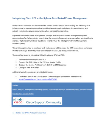
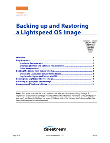
Chapter 1: Introduction1-2WPCM450 Block DiagramThe following diagram represents a typical system setup for the WPCM450 e-up & CTRLSouth BridgeRMIISerial PortWPCM450RMIIVGASPISensorsEthernet CTRLOnboard LAN1RS232PHYRJ45Serial PortRJ45Dedicated LANNOR FlashDDR21-3Introduction to the IPMI PlatformThe Intelligent Platform Management Interface (IPMI) provides remote access tomultiple users at different locations for networking. It also allows a system administrator to monitor system health and manage computer events remotely.IPMI operates independently from the operating system. When used with an IPMIManagement utility installed on the motherboard, the WPCM450 BMC Controller willconnect the South Bridge to other onboard components, providing remote networkinterface via serial links. With the WPCM450 Controller and the IPMI firmware builtin, the Supermicro motherboard allows the user to access, monitor, diagnose, andmanage a remote server via Console Redirection. It also provides remote access tomultiple users from different locations for system maintenance and management.1-3
SMT IPMI User's Guide1-4Motherboards SupportedThis version of SMT IPMI is supported by the motherboards listed in the table below.If your motherboard is not included in the table, please refer to the motherboardproduct page on our website at www.supermicro.com and download the right BMC/IPMI user's guide for your motherboard.Intel Dual-ProcessorMotherboards supported(-F models only)Intel Single-ProcessorMotherboards supported(-F models only)AMD Motherboards supported(for -F models only)X8DTL-3F/-6F/iFX7SPA-HFH8DGG-QFX8DTN -FX7SPE-HFH8DGT-HF/HIBQFX8DTU-6F /6TF /LN4F X8SIL-F/F X8SIT-F1-5An Important Note to the UserThe graphics shown in this user's guide were based on the latest informationavailable at the time of publishing of this guide. The IPMI screens shown on yourcomputer may or may not look exactly like the screen shown in this user's guide.1-4
Chapter 2: Configuring BMC/IPMI SettingsChapter 2Configuring the IPMI SettingsWith the Nuvoton WPCM450 BMC Controller and the IPMIView firmware built in,Supermicro motherboards allow the user to access, monitor, manage and interfacewith multiple systems in different remote locations. The necessary firmware for accessing and configuring the IPMI settings are available on Supermicro's websiteat hppt://www.supermcro.com/products/nfo/ipmi.cfm. This section provides detailedinformation on how to configure the IPMI settings.2-1Configuring BIOSBefore configuring IPMI, follow the instructions below to configure the system BIOSsettings.Enabling COM Port for SOL (IPMI)1. Press the Del key at bootup to enter the BIOS Setup utility.2. Select Advanced and press Enter to enter the Advanced menu.3. From the Advanced menu, select Remote Access and press Enter .4. Make sure that the COM port for SOL (COM2 or COM3) is enabled (markedwith "*"). If not, Select the port for SOL and press Enabled . (For IPMI towork properly, BIOS will set the console redirection on this port by default.)2-1
SMT IPMI User's GuideB. Enabling All Onboard USB ports1. Press the Del key at bootup to enter the BIOS Setup utility.2. Select Advanced and press Enter to enter the Advanced menu.3. Select Advanced Chipset Control and press Enter .4. From the Advanced Chipset Control submenu, select South Bridge Controland press Enter .5. Make sure that all onboard USB ports are enabled (highlighted). If not, SelectUSB Functions and press Enabled or select the number of onboard USBports or press Enter to enable all onboard USB ports. (This is required forKVM to work properly.)2-2
Chapter 2: Configuring BMC/IPMI SettingsC. Configuring IP and MAC Addresses using BIOS1. Press the Del key at bootup to enter the BIOS Setup utility.2. Select Advanced and press Enter to enter the Advanced menu.3. From the Advanced menu, select IPMI Configuration and press Enter .4. From the IPMI Configuration submenu, select Set LAN Configuration andpress Enter to set IP and MAC addresses.2-2 Configuring the IP/MAC Addresses for RemoteServersNote: The DHCP (Dynamic Host Configuration Protocol) is on by default.To change the manufacturer default setting, please use the ipmicfg utilityor the BIOS Setup utility.Using the IPMICFG Utility to Set the IP/MAC Addresses forRemote Servers1. Run the ipmicfg utility from the bootable CD that came with your shipment.2. Follow the instructions given in the Readme.txt file to configure Gateway IP/Netmask IP addresses, enable/disable DHCP, and configure other IPMI settings.IPMICFG Version 1.35 (Build 2010-04-28) Copyright 2010 Super Micro Computer,Inc. Usage: IPMICFG Parameters (Example: IPMICFG -m 172.31.1.84)2-3
SMT IPMI User's Guide-mShows IP and MAC-m IPSets IP (format: ###.###.###.###)-a MACSets MAC (format: ##:##:##:##:##:##)-kShows Subnet Mask-k MaskSets Subnet Mask (format: ###.###.###.###)-dhcpGets the DHCP status-dhcp onEnables the DHCP-dhcp offDisables the DHCP-gShows Gateway IP-g IPSets Gateway IP (format: ###.###.###.###)-rBMC cold reset-garp onEnables the Gratuitous ARP-garp offDisables the Gratuitous ARP-fdResets to the factory defaults-verGets the firmware revision-vlanGets VLAN status-vlan on (VLANtag)Enables the VLAN and sets the VLAN tag (If VLANtag is not given, it uses previously saved value.)-vlan offDisables the VLAN-rawSends a RAW IPMI request and print the response.Format: NetFn LUN Cmd [Data1.DataN].-sdrShows SDR records and reading-sdr del SDR ID Deletes SDR record-sdr backup FILE Backups SDR to file-sdr restore FILE Restores SDR from file-sdr ver [ V1 v2 ]Retrieves and sets SDR version (V1, V2)-sel infoShows SEL info-sel listShows SEL records-sel delDeletes all SEL records-fru infoShows FRU inventory area info-fru listShows all FRU values-fru helpShows FRU Write help-fru cthelpShows chassis type code-fru Field Shows FRU field value-fru Field Value Writes FRU-fru backup File Backs up FRU to file-fru restore File Restores FRU from file-fru ver [ V1 V2 ]Retrieves and sets FRU version (V1, V2)2-4
Chapter 2: Configuring BMC/IPMI Settings2-3Connecting to the Remote ServerUsing the IPMIView to Connect to the Remote Server1. Connect a LAN cable to the onboard LAN1 port or the dedicated IPMI LANport.2. Choose a computer that is connected to the same network and open theIPMIView utility.3. Go to File New System. Enter the System Name, IP Address of LAN1 (orthe dedicated LAN, and the Description in the appropriate fields, and press Enter .4. Select the system from the IPMI Domain. Enter the Login ID and Password inthe appropriate fields to log in to the IPMIView utility.Using the Browser to Connect to the Remote Server1. Connect a LAN cable to the onboard LAN1 port or the IPMI LAN port.2. Choose a computer that is connected to the same network and open thebrowser.3. Enter the IP address of each server that you want to connect to in the address bar of your browser.4. Once the connection is made, the Login screen as shown on the next pagewill display.Notes:1. The default network setting is "Failover", which will allow the IPMI toconnect to the network through a shared LAN port (onboard LAN Port 1or 0) or through the IPMI Dedicated LAN Port. If the IPMI must be connected through a specific port, please change the LAN configuration settingunder the Network Settings.2. For IPMI to work properly, please enable all onboard USB ports and theCOM port designated for SOL (IPMI) on the motherboard. All USB portsand the COM port for IPMI are enabled in the system BIOS by default.The COM port for IPMI is marked with "*" in the BIOS. It is usually listedas COM2 or COM3 in the BIOS. Refer to Section 2-1 Configuring BIOSfor more information.2-5
SMT IPMI User's Guide2-4 Accessing the Remote Server via ConsoleRedirection Using the BrowserTo Log In to the Remote ConsoleOnce you are connected to the remote server via IPMI Console Redirection, thefollowing IPMI Login screen will display.1. Enter your Username in the Username fields.Note: The manufacturer default username and password are ADMIN/ADMIN.Once you have logged into the BMC using the manufacturer default password,be sure to change your password for security purpose.2. Enter your Password in the Password box and click Login .3. The Home Page will display as shown on the next page.Note 1: To use the IPMIView utility for Console Redirection, please refer to theIPMIView User's Guide for instructions.Note 2: The Administrator account cannot be deleted.2-6
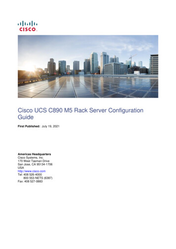
Chapter 2: Configuring BMC/IPMI Settings2.5IPMI Main ScreenThe IPMI Main screen displays the following information.45123The IPMI Main screen displays system information, including the following:1. The Menu Bar: The menu bar on the top displays System Information, ServerHealth, Configuration, Remote Control, Virtual Media, Maintenance, andMiscellaneous. Click an item on the Menu Bar to access an IPMI feature andconfigure its settings.2. The Options Window: This window displays IPMI submenu items. Click anitem in this window to configure the setting.3. The Main Display Area: This area displays the contents of the particular section. Click an item in this area to configure the setting.4. System Health Status: This icon displays the health status of the server. Green: It indicates that the server is normal. Orange: At least an alert has occurred. Take proper actions to ensure systemhealth. Red: At least one critical condition has occurred. Immediate attention is requiredto resolve the critical condition for the server to function normally.5. Language Select: From the pull-down menu, select a language. English Japanese2-7
SMT IPMI User's Guide2.6System StatusOnce you've logged into the remote server, the IPMI Main scree will display.121. System Information: This item displays the following firmware information. Firmware Revision Firmware Build Time IP Address MAC Address Preview Screen Power Control: This feature allows the user to launch the remote console byclicking a preview screen.2. FRU Reading: Click this item to display the following BMC FRU (Field Replaceable Unit) information. You can also configure the FRU settings by usingthe Supermicro IPMIView or ipmicfg utility. FRU Device ID Chassis Information Board Information Product Information2-8
Chapter 2: Configuring BMC/IPMI Settings2.7Server HealthThis feature allows the user to set Server Health settings. To access Server Healthinformation, follow the instructions below.121. Click Sensor Readings to access information on sensor readings asshown on the next page.2. Click Event Log to access event logs.2-9
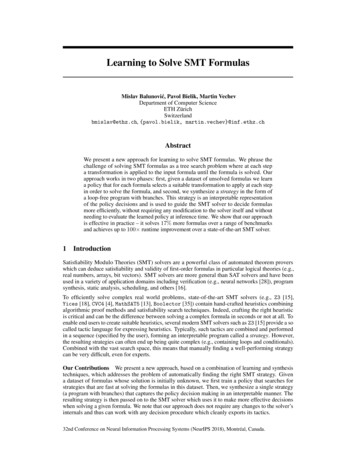
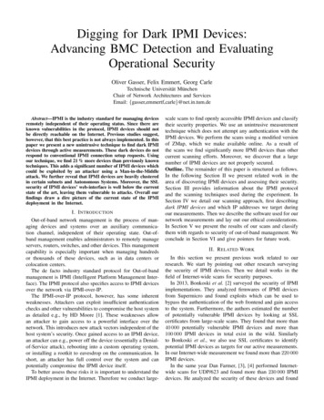
SMT IPMI User's Guide2.7.1 Sensor ReadingsThis page displays sensor readings for the remote console.43512671. From the pull-down menu, select a sensor type (category). The optionsinclude the following. All Sensors Temperature Sensors Voltage Sensors Fan Sensors Physical Security/(Chassis Intrusion) Power Supply OEM Reserved:2. A senor color that is displayed in front of an sensor indicates the status of thesensor. Green: It indicates that the sensor reading is normal. The system functionsnormally.2-10
Chapter 2: Configuring BMC/IPMI Settings Amber: There is an alert on the sensor reading. Attention is needed to ensurethat the system is functioning properly. Red: One or more sensors have reached the critical state. Immediate action isneeded to resolve the problem.3. Name of the Sensor: This column displays the names of the sensors that arecurrently active in system monitoring, including system temperature, CPUtemperature, fan speeds, CPU core voltages, 3.3Vcc, and 12V voltagemonitoring.4. Status: This column indicates the status of each sensor reading.5. Reading: This column indicates the reading of each sensor.6. Refresh: Click this item to refresh the page.7. Show Thresholds: Click this item to display senor thresholds.2-11
SMT IPMI User's Guide2.7.2 Event LogThis page displays a record of critical system monitoring events. The event logindicates the time when a critical condition had occurred and when this conditionwas resolved. You can choose a specific event category from the pull-down menuto display events included in this category.11. Event Category: From the pull-down menu, select an event category todisplay. Sensor Specific Events BIOS Generated Events System Management Software Events2-12
Chapter 2: Configuring BMC/IPMI Settings2.8ConfigurationThis feature allows the user to configure various network settings. When you clickthe Configuration icon on the menu bar, the following screen will display.This section allows the user to configure the following settings.Alerts: Use this item to configure alert destination settings. Date & TimeLDAP: Use this item to configure LDAP (Lightweight Directory Access Protocol)settings for authentication and access to the LDAP server.Active Directory: Use this item to configure the settings for authentication andaccess to the Active Directory server. Radius: Use this item to configure the settings for authentication and accessto the Radius server. Mouse mode Network Dynamic DNS Remote Session SMTP SSL Certificate2-13
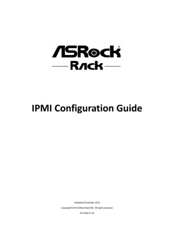
SMT IPMI User's Guide2.8.1 Configuring the Alerts SettingsThis feature allows the user to configure Alert settings. When you click the Alerts icon in the menu bar, the following screen will display.1432To setup an alert or to modify an alert setting, do the following.1. Click Alerts to activate the alert submenu.2. Click Modify to configure or modify the settings of an alert.3. Send Test Alert is used to check if the alerts have been set and sent out correctly.4. Click Delete to delete an alert.2-14
Chapter 2: Configuring BMC/IPMI SettingsTo Setup an Alert234567Follow the steps below to setup an alert.1. Select Alert Severity.2. Enter the IP address and/or the email address to receive the SNMP Trap.3. Enter a subject or a message if applicable.2-15
SMT IPMI User's Guide2.8.2 Configuring Date and Time SettingsThis feature allows the user to configure the time and da
SMT IPMI User's Guide Contacting Supermicro Headquarters Address: Super Micro Computer, Inc. 980 Rock Ave. San Jose, CA 95131 U.S.A. Tel: 1 (408) 503-8000 Fax: 1 (408) 503-8008 Email: marketing@supermicro.com (General Information) support@supermicro.com (Technical Support) Web Site: www.supermicro.com Europe Address: Super Micro Computer B.V.