Transcription
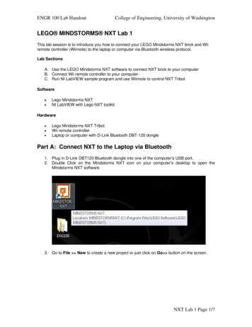
ENGR 100 Lab HandoutCollege of Engineering, University of WashingtonLEGO MINDSTORMS NXT Lab 1This lab session is to introduce you how to connect your LEGO Mindstorms NXT brick and Wiiremote controller (Wiimote) to the laptop or computer via Bluetooth wireless protocol.Lab SectionsA. Use the LEGO Mindstorms NXT software to connect NXT brick to your computerB. Connect Wii remote controller to your computer.C. Run NI LabVIEW sample program and use Wiimote to control NXT Tribot.Software Lego Mindstorms NXTNI LabVIEW with Lego NXT toolkitHardware Lego Mindstorms NXT TribotWii remote controllerLaptop or computer with D-Link Bluetooth DBT-120 donglePart A: Connect NXT to the Laptop via Bluetooth1. Plug in D-Link DBT120 Bluetooth dongle into one of the computer’s USB port.2. Double Click on the Mindstorms NXT icon on your computer’s desktop to open theMindstorms NXT software.3. Go to File New to create a new project or just click on Go button on the screen.NXT Lab 1 Page 1/7
ENGR 100 Lab HandoutCollege of Engineering, University of Washington4. Press the orange, square Enter button on the Mindstorms NXT brick to turn the robot on.5. Make sure you have Bluetooth icon and “ ” shown on the upper left corner of the NXTscreen. If not , try to use the arrow button on the NXT brick to choose Bluetooth icon andpress the orange Enter button and choose ON/Off icon to turn on Bluetooth function ofNXT and also make use NXT brick is visible to other Bluetooth device by choosingVisibility icon Visible.6. Click on the NXT Window button on the lower right of the screen as shown here:7. There will be a connection dialog window prompt out. If you have everything setupcorrectly, you can see the detailed information about your NXT brick including battery life,free storage space on the NXT block, and the version of the firmware installed, whichindicates that the connection is established. If you can’t have the NXT connected now,click on the Scan button to detect the NXT brick that is visible to the PC. The name ofNXT Lab 1 Page 2/7
ENGR 100 Lab HandoutCollege of Engineering, University of Washingtonyour NXT brick should appear on the list of the dialog window. Click on your robot’sname, and then click Connect. You may have the query prompt out on your NXT brickwindows to ask you to key in passkey, just press Orange button to accept the defaultvalue (1234). Once you establish the connection, you can see the icon on upper leftcorner of your NXT brick windows changed from “ ” to “ ” to indicate you theconnection is established.8. Click on the Memory tab at the top of the dialog window to see what programs arecurrently loaded onto the NXT block.9. Close the dialog window, and now you can try to program the code in NXT environmentor close the whole NXT programming environment and go to the section B to connectWiimote to your PC. Notice that once you close the Mindstorms NXT program, the iconon your NXT brick windows will change back to “ ”.Questions:a) What should you do if you want to change the name of your robot?b) What should you do if you want to download the program to your robot but the memory isfull already?NXT Lab 1 Page 3/7
ENGR 100 Lab HandoutCollege of Engineering, University of WashingtonPart B: Connect Wiimote to the ComputerBefore this part of exercise, make sure you have plugged in the Bluetooth dongle and finishedPart A exercise. Now check that the Wiimote has batteries in it. And follow the procedure.1. Double Click on the Bluetooth icon on the notification area of windows task bar, i.e. lowerleft side of windows desktop. You will have a window showing Bluetooth Devices.2. Click Add, even you already have Nintendo RVL-CNT-01 device shown on your list.3. Press and hold 1 and 2 buttons of Wiimote at the same time for a while until you see theLEDs flash on and off. Check the check box of dialog and click Next.4. Wait for a while for window to search Bluetooth devices. And you will see the followingwindow if you have Wiimote around you.NXT Lab 1 Page 4/7
ENGR 100 Lab HandoutCollege of Engineering, University of Washington5. Choose Nintendo RVL-CNT-01 device and click Next.6. Select Don’t use a passkey for this device. Before you move on, make sure the LED onyour Wiimote are still flashing, or you may need to press and hold 1 and 2 buttons of yourWiimote again to make it flash before you click Next.7. Now click Next, you will see that the window will try to connect and install the driver foryour Wiimote.NXT Lab 1 Page 5/7
ENGR 100 Lab HandoutCollege of Engineering, University of Washington8. Now you have Wiimote connected with your PC. Double Click on Wiimote Test icon onyour Desktop to check if you can actually read the sensor data from Wiimote and controlthe LEDs on Wiimote.NXT Lab 1 Page 6/7
ENGR 100 Lab HandoutCollege of Engineering, University of WashingtonPart C: Run LabVIEW Sample ProgramFor this part of exercise, you will see that we can achieve much more functionality than LEGOMindstorms NXT program. For example, we can use LabVIEW to accomplish the communicationbetween different kinds of Bluetooth devices and won’t be constrained in communication betweenNXT bricks and PC. Before starting this part of exercise, make sure you already finish theexercise of Part A and B correctly. Follow the procedure to run the sample program. In this demo,you will be able to use Wiimote to control the rotation speed and direction of motor A of LEGONXT brick by flipping Wiimote forward and backward.1. Double click on the file, motor A with Wiimote.vi, located on the Desktop ENG100 My LabVIEW example run in pc, to invoke LabVIEW programming environment andprepare to run the demo program.on the LabVIEW Toolbar to run the demo program. Notice2. Click on the Run buttonthat the system will take a few seconds to connect Wiimote and NXT brick to your PC.Once the connection is established, you will see that the lights of LEDs on Wiimote willbe turned off and the icon on the NXT brick screen will be changed from “ ” to ” ”.3. On the left half part of LabVIEW window is the control and information of NXT brick. Youcan try to control different motor of NXT brick by changing Output Port from Port A to PortB or C. On the right half part of windows is the information about Wiimote Status. Youcan see the readings of different sensors and tell which button is pressed.4. Press button A on your Wiimote to stop the demo program, or use mouse to click onSTOP button located on the middle of demo program window.Questions:a) What should you do if you have error alert message shown up?b) How to use Wiimote to control motor B and C at the same time?NXT Lab 1 Page 7/7
ENGR 100 Lab HandoutCollege of Engineering, University of WashingtonLEGO MINDSTORMS NXT Lab 2In this lab session, you will learn the basic knowledge of LabVIEW programming environment andpractice the NXT programming using LabVIEW NXT toolkit.Lab SectionsA. Get familiar with LabVIEW environmentB. Write your code to get readings of sensors on NXT brickSoftware Lego Mindstorms NXTNI LabVIEW with Lego NXT toolkitHardware Lego Mindstorms NXT TribotLaptop or computer with D-Link Bluetooth DBT-120 donglePart A: Get Familiar with LabVIEW Environment1. Open and run LabVIEW 8.6 by clicking on Windows Start icon All Programs National Instruments LabVIEW 8.6. Then you can have LabVIEW 8.6 Startup Screenas below.2. You can start from a blank VI by clicking on New Blank VI to program your code fromdraft. Or you may start from a template/example by clicking on Examples FindExamples to modify the existing code for your particular application. To begin with, let’sstart from a blank VI. You will have the following two windows for your new VI. The FrontPanel window is the interface for users to interact with your program. You can design theoutlook of your program here and the two main objects for front panels are controls andNXT Lab 2 Page 1/11
ENGR 100 Lab HandoutCollege of Engineering, University of Washingtonindicators. You can think of controls as inputs and indicators as outputs. The BlockDiagram window is the place for you to write graphical codes that process the user inputsand the logic of your functions.3. You may rearrange the places of windows by choosing Windows Tile Left and Rightto have them shown on the screen at the same time.NXT Lab 2 Page 2/11
ENGR 100 Lab HandoutCollege of Engineering, University of Washington4. To view and see what Controls or Indicators you can put on the front panel, selectVIEW Controls Palette. You can customize the palette view by clicking on View iconon the controls palette. To put a control or indicator on the front panel, you just click onthe icon on the palette you want first, and put it on the front panel.Tips: move your mouse to any empty space on the front panel and right-click your mouse toinvoke display of controls palette. And tack down controls palette by clicking the pushpin icon onthe top left corner of the palette.NXT Lab 2 Page 3/11
ENGR 100 Lab HandoutCollege of Engineering, University of Washington5. To view and see what Functions or Structures you can use in your graphical code onthe block diagram window, select VIEW Functions Palette. Or use the same trick asbefore, display the functions palette by right-clicking on the empty space of your blockdiagram window.NXT Lab 2 Page 4/11
ENGR 100 Lab HandoutCollege of Engineering, University of Washington6. Once you finish your coding, click the Run button on the Status Toolbar. There are otherbuttons on the toolbar, such as continuous run button, abort button, pause button, etc.Don’t forget to get help online by choosing Help Show Context Help or pressing Ctrl H to invoke help window. Please refer to the reference material for more details.HW: Read Introduction to LabVIEW in 3 hours material.NXT Lab 2 Page 5/11
ENGR 100 Lab HandoutCollege of Engineering, University of WashingtonPart B: Write VI Code to Get Readings of NXT SensorsFor this part of exercise, you will learn how to write the codes to read the sensors’ values on NXTbrick. There are two ways to connect the NXT brick with your PC. One is connected via USBcable, while the other one is connected via Bluetooth. So you can write a code for users to decidewhich way they would like to use. If you want to use Bluetooth communication, please follow theprocedures mentioned in Lab 1 Part A to check if you can connect successfully.1. Open LabVIEW 8.6 by clicking on Windows Start icon All Programs NationalInstruments LabVIEW 8.6. Then start a blank VI by clicking on New Blank VI.2. For the convenience of coding, let’s tack down the NXT Toolkit function palette on theblock diagram window. Right click on any empty space on block diagram window, click onbutton at the bottom of the palette. Select Addons NXT Direct Commands.theTack down pushpin icon on the top left corner of the palette.3. Select NXT Direct Commands Connection Find NXT, and place it on the blockdiagram.4. Right-Click on the upper left input corner of the Find NXT VI icon, i.e., the NXT nameinput port. You may press Ctrl H to invoke help windows to help you find out thecorresponding input port easier. Move your cursor to a certain I/O port of the icon, andyou will see the corresponding flashing indicator on the help window. Select Create Constant from the shortcut menu and key in the name of your NXT brick. In this demo,the name of NXT brick is FNXT. So after you complete this step, the block diagramwindow would look like the figure below.NXT Lab 2 Page 6/11
ENGR 100 Lab HandoutCollege of Engineering, University of WashingtonNote: Make sure the capitalization of your NXT brick’s name is correct.5. In order to use Bluetooth communication, we need to have a parameter in the program totell which connection type we are going to use. Right-Click the Connection type (USB)input port of the Find NXT VI icon, i.e., the second input port on the left side of the icon,and select Create Constant from the shortcut menu. Change the connection type fromUSB to Bluetooth by clicking the USB constant and select Bluetooth from the shortcutmenu.Question: What should you do if you want users to be able to choose the connection type bythemselves? (Hint: get something on the interaction window)6. From the Function Palette, select NXT Direct Commands Connection CreateNXTObject, and place it next to the Find NXT VI icon. Wire the VISA resource stringfrom the output put of the Find NXT icon to the VISA resource string input port of theCreate NXTObject icon. Wire the error information of two icons, from error out output ofthe Find NXT icon to the error in input of the Create NXTObject icon.Tip: When you select a new VI such as Create NXTObject in this case and place it next to therelating VI icon, try to move it closer to the relating VI icon and you will find that LabVIEW willconnect the corresponding ports for you.7. Click Up to Owning Palette icon on the function palette, and select NXT DirectCommands Utilities Get Battery Level, and place it next to the Create NXTObjectVI icon. Wire the NXT Object information and error information of these two VI icons, oruse the tip of step 6 to wire these two VI icons.NXT Lab 2 Page 7/11
ENGR 100 Lab HandoutCollege of Engineering, University of Washington8. To get the battery level value shown on the front panel, right-click on the second outputport of Get Battery Level VI icon, i.e., millivolts output port, select Create Indicatorfrom the shortcut menu.9. The last step is to destroy the NXT object that you create in your previous step. SelectNXT Direct Commands Utilities Destroy NXTObject, and place it next to GetBattery Level VI icon, and wire the NXT Object information and error information ofthese two VI icons, or use the tip of step 6 to wire these two VI icons.10. Now you finish the coding to read battery level of your NXT brick. Press Ctrl E to switchto the front panel window and click the Run button on the toolbar to run your first NXTprogram.Exercise: Try to modify this code to get more NXT device information, firmware version, andrename NXT brick by using existing VIs in NXT Direct Commands Utilities.NXT Lab 2 Page 8/11
ENGR 100 Lab HandoutCollege of Engineering, University of Washington11. There are four different sensors that you can connect to your NXT brick. Make sure youconnect with the default setting. Now let’s modify the code we wrote to get the reading ofthe light sensor. First delete the wires between Destroy NXTObject and Get BatteryLevel VI icons.12. Select NXT Direct Commands Input Read Light Sensor, and place it next to GetBattery Level VI icon. Wire the NXT Object information and error information of theseVI icons as following.13. Right-Click the scaled value output port of the Read Light Sensor VI icon, and selectCreate Indicator from the shortcut menu. Now you have two indicators on the frontpanel. Run this program to get the battery level and light sensor readings once.14. Normally, we would like to keep getting the reading until the user presses STOP button.To do this, we need to add a while loop structure in the program. Right-click on anyempty space of the block diagram. From the short cut functions palette, selectExpress Execution Control While Loop, drag a square enclosing Read LightSensor and Scaled Value iconsNXT Lab 2 Page 9/11
ENGR 100 Lab HandoutCollege of Engineering, University of Washington15. LabVIEW will automatically create a control button called STOP on the front panel. Userscan press this button to stop the while loop and let the program goes forward to the end.Click the Run button on the toolbar and see the values of two indicators. Notice that thevalue of the battery level won’t keep changing, while the value of the light sensor willchange with time until the STOP button is pressed.NXT Lab 2 Page 10/11
ENGR 100 Lab HandoutCollege of Engineering, University of Washington16. Save the code for future usage.Exercise: Try to modify this code to get other sensors’ readings by using existing VIs in NXTDirect Commands Input, such as Read Touch Sensor, Read Sound Sensor, and ReadUltrasonic Sensor. Remember to create the corresponding indicator for each sensor.NXT Lab 2 Page 11/11
ENGR 100 Lab HandoutCollege of Engineering, University of WashingtonLEGO MINDSTORMS NXT Lab 3In this lab session, you will learn how to write a code to read the motor status of your NXT robotand make the motors move using LabVIEW NXT toolkit.Note: Please follow the procedures mentioned in Lab 1 Part A first to make sure that you canconnect your NXT robot to PC via Bluetooth successfully.Lab SectionsA. Read the motor status of your NXT robotB. Write the code to control motors of your NXT robotSoftware Lego Mindstorms NXTNI LabVIEW with Lego NXT toolkitHardware Lego Mindstorms NXT TribotLaptop or computer with D-Link Bluetooth DBT-120 donglePart A: Read the motor status of NXT robot1. To save our time, let’s not start from scratch but modify the code we have from previouslab. Open the file you create from Lab2 Part B. Delete the code inside the while loopstructure except the STOP button.2. Select NXT Direct Commands Output Get Output Values, and place it inside thewhile loop structure. Wire the NXT Object information and error information of these VIicons as following.NXT Lab 3 Page 1/9
ENGR 100 Lab HandoutCollege of Engineering, University of Washington3. Right-Click the second input port of Get Output Values VI icon, i.e., Output Port (PortA), and select Create Control from the short cut menu. With default setting, motor A isconnected to output port A of NXT brick. Users can read different motor status bychanging the value of this control.4. Right-Click the second output port of the Get Output Values VI icon, i.e., Output PortInfo, and select Create Indicator from the shortcut menu.NXT Lab 3 Page 2/9
ENGR 100 Lab HandoutCollege of Engineering, University of Washington5. Wire the NXT Object information and error information of Get Output Values VI iconand Destroy NXTObject VI icon as following.6. Now you can run the program and get one updating motor status. Try to rotate the motorby hands and observe the indicator values on the front panel.7. To improve the code so that the program would stop the while looping if there is any erroron NXT or communication during execution, right-click the error wire in the while loopstructure. Select Cluster, Class, & Variant Palette Unbundle By Name from the shortcut menu. Place it inside the while loop structure and connect the error wire to it.NXT Lab 3 Page 3/9
ENGR 100 Lab HandoutCollege of Engineering, University of Washington8. Right-Click the green dash wire inside the while loop structure. Select BooleanPalette Or from the short cut menu, and place it inside the while loop structure.NXT Lab 3 Page 4/9
ENGR 100 Lab HandoutCollege of Engineering, University of Washington9. Delete the green dash wire and reconnect the wires as below.10. With this setup, the program would stop running if there is any error occurs or if the stopbutton is pressed.11. Add a 40 millisecond time delay in the while loop structure to prevent the code occupyingthe whole CPU resource. Right-click on any empty space on the block diagram windows,select Programming Timing Wait Until Next ms Multiple from the short cut menu,and place it inside the while loop structure. Right-click the input port of this time delayicon and select Create Constant. Key in the value 40 for indicating 40 ms time delay.NXT Lab 3 Page 5/9
ENGR 100 Lab HandoutCollege of Engineering, University of Washington12. Now you finish the coding for reading the motor status. And the front panel should appearsimilar to the figure below.Exercise: Modify the code to enable reading ABC motor status in while loop sequentially.Part B: Control the motors of NXT robot1. Open the file you create from Lab3 Part A. Delete the wires between Get Output ValuesVI icon and Destroy NXTObject VI icon. Select and place the following two VI icon insidethe while loop structure from functions palette NXT Direct Commands Output SetOutput Values and NXT Direct Commands Utilities Keep Alive. Select NXTDirect Commands Output Motor Stop, and place it outside the while loop. Connectthese VI icons as following.NXT Lab 3 Page 6/9
ENGR 100 Lab HandoutCollege of Engineering, University of Washington2. Wire the Output Port (Port A) to Set Output Values VI icon and Motor Stop VI icon asfollowing.3. Right-Click the third input port of the Set Output Values VI icon, i.e., Output Port Info,and select Create Control from the shortcut menu.NXT Lab 3 Page 7/9
ENGR 100 Lab HandoutCollege of Engineering, University of Washington4. Rename the control, Output Port Info 2, to Set Output Port Info. Rename theindicator, Output Port Info, to Read Output Port Info.5. Now you should have the front panel similar to the following figure.6. Press the run button on the toolbar and you will find that the motor won’t move. Becausewe didn’t have the proper setting for the motor from Set Output Port Info control.7. Click the RunState control, and change the value from RUN STATE IDLE toRUN STATE RUNNING.8. Click the Mode control and change the value from COAST to MOTOR ON BRAKE REGULATED.NXT Lab 3 Page 8/9
ENGR 100 Lab HandoutCollege of Engineering, University of Washington9. Click the Power control, and change the value from 0 to 10.10. From the windows menu, select Edit Make Current Values Default.11. Save the code for future usage. Now you can press the Run button from the toolbar andsee the motor rotating until you press the STOP button.Exercise: Modify the code to control motor B and C simultaneously.NXT Lab 3 Page 9/9
ENGR 100 Lab HandoutCollege of Engineering, University of WashingtonLEGO MINDSTORMS NXT Lab 4In this lab session, you will learn how to write a code to communicate Wiimote via Bluetooth usingLabVIEW.Note: Please follow the procedures mentioned in Lab 1 Part B first to make sure that you canconnect your Wiimote to PC via Bluetooth successfully.Lab SectionsA. Read XYZ acceleration status of WiimoteB. Read button status of WiimoteSoftware NI LabVIEW with Nintendo's Wiimote library by Brian PeekHardware Nintendo's WiimoteLaptop or computer with D-Link Bluetooth DBT-120 donglePart A: Read XYZ acceleration status of Wiimote1. Open LabVIEW 8.6 by clicking on Windows Start icon All Programs NationalInstruments LabVIEW 8.6. Then start a blank VI by clicking on New Blank VI.2. From the function palette, select Connectivity .NET Constructor Node, and place iton the block diagram. You will have a popup window asking you to select .NETNXT Lab 4 Page 1/9
ENGR 100 Lab HandoutCollege of Engineering, University of WashingtonConstructor. Click the Assembly column, from the shortcut menu roll down the scroll barand select WiimoteLib(1.6.0.0).3. From the Objects column, roll down the scroll bar and select Wiimote. Then click OK.4. From the function palette, select Connectivity .NET Invoke Node (.NET), and placeit next to the Constructor Node on the block diagram. Wire the reference and errorinformation between Constructor Node and Invoke Node. Click on the method of theInvoke Node and select Connect() from the short cut menu.NXT Lab 4 Page 2/9
ENGR 100 Lab HandoutCollege of Engineering, University of Washington5. From the function palette, select Connectivity .NET Invoke Node (.NET), and placeit next to the previous Invoke Node on the block diagram. Wire the reference and errorinformation between these two nodes. Click on the method of the Invoke Node andselect SetReportType(InputReport type Boolean continuous) from the short cut menu.6. Right-Click the first input port of this Node, i.e., type, and select Create Constant fromthe short cut menu.7. Change the constant value from Status to IRAccel. Right-Click the second input port ofthe same Node, i.e., continuous, and select Create Constant from the short cut menu.Change the constant value from False to True by clicking on T character of the constant.8. From the function palette, select Connectivity .NET Property Node (.NET), andplace it next to the previous Invoke Node on the block diagram. Wire the reference anderror information between these two nodes. Click on the Property of the Property Nodeand select WiimoteState from the short cut menu.NXT Lab 4 Page 3/9
ENGR 100 Lab HandoutCollege of Engineering, University of Washington9. From the function palette, select Connectivity .NET Property Node (.NET), andplace it next to the previous Property Node on the block diagram. Wire the referencefrom output port of previous Property Node, i.e., WiimoteState and error informationbetween these two nodes. Click on the Property of the Property Node and selectAccelState from the short cut menu.10. From the function palette, select Connectivity .NET Property Node (.NET), andplace it next to the previous Property Node on the block diagram. Wire the referencefrom output port of previous Property Node, i.e., AccelState and error informationbetween these two nodes. Click on the Property of the Property Node and selectValues from the short cut menu.11. From the function palette, select Connectivity .NET Property Node (.NET), andplace it next to the previous Property Node on the block diagram. Wire the referencefrom output port of previous Property Node, i.e., Values and error information betweenthese two nodes. Move the cursor to the button edge of the Node. You will see a pair ofBlue Square shown up at the top and button edges of the icon. Drag the button edgedown to have three Property sets in the Node. Click on each Property of the Node andselect X, Y, and Z from the short cut menu respectively.NXT Lab 4 Page 4/9
ENGR 100 Lab HandoutCollege of Engineering, University of Washington12. Create indicators for the outputs of the Point3F Property Node by right-clicking eachoutput ports and selecting Create Indicator from the short cut menu respectively.13. From the function palette, select Connectivity .NET Invoke Node (.NET), and placeit next to the previous Property Node on the block diagram. Wire the reference from theWiimote Property Node and error information from the Point3F Property Node. Clickon the method of the Invoke Node and select Disconnect() from the short cut menu.14. From the function palette, select Connectivity .NET Close Reference, and place itnext to the previous Invoke Node on the block diagram. Wire the reference and errorinformation between these two icons.NXT Lab 4 Page 5/9
ENGR 100 Lab HandoutCollege of Engineering, University of Washington15. Right click the output port of the Close Reference VI icon, and select Dialog & UserInterface Palette Simple Error Handler, place it next to the Close Reference VI iconon the block diagram. Wire the error information between these two icons.16. Save the code for further usage.Exercise: Add a while loop structure in the code to keep updating the readings ofWiimote acceleration status.NXT Lab 4 Page 6/9
ENGR 100 Lab HandoutCollege of Engineering, University of WashingtonPart B: Read Button Status of Wiimote1. Open the file you create from Lab4 Part A. Open the block diagram window. Move thecursor to the button edge of the WiimoteState Property Node. You will see a pair ofBlue Square shown up at the top and button edges of the icon. Drag the button edgedown to have another Property set in the Node. Click the second Property of theWiimoteState Property Node, and change the property from BalanceBoardState toButtonState from the short cut menu.2. From the function palette, select Connectivity .NET Property Node (.NET), andplace it next to the WiimoteState Property Node on the block diagram. Wire thereference from the second output port of WiimoteState Property Node, i.e.,ButtonState and error information between these two nodes. Click the Property of theButtonState Property Node and select A from the short cut menu.3. Right-click the output port, A, of the ButtonState Property Node. Select Create Indicator from the short cut menu to have an indicator on the front panel showing thestatus of Button A of Wiimote.NXT Lab 4 Page 7/9
ENGR 100 Lab HandoutCollege of Engineering, University of Washington4. To merge the error wires in the program, right-click the error output port of ButtonStateProperty Node. Select Dialog & User Interface Palette Merge Errors from the shortcut menu, and place it on the block diagram.5. Delete the error wire between Simple Error Handler and Close Reference VI icons.Wire the error outputs of Simple Error Handler VI icon and ButtonState Property NodeVI icon to the inputs of Merge Errors VI icon, respectively. And wire the error output ofMerge Errors VI icon to the input of Simple Error Handler VI icon.6. Now you have the code that can read one button status and XYZ acceleration Status ofWiimote.NXT Lab 4 Page 8/9
ENGR 100 Lab HandoutCollege of Engineering, University of WashingtonExercise:a) Add a while loop structure in the code to keep updating the readings of Wiimote button status.(Don’t forget to add a 40 ms time delay in your while loop structure)b) Modify the code so that you can read more than one button status.c) Combine the codes of Wiimote and NXT motor control you learn from Lab3 and Lab4 toenable users to use Wiimote to control NXT motor. (Hint: use the value of acceleration statusof Wiimote as the input value of motor power parameter setting.)NXT Lab 4 Page 9/9
Lego Mindstorms NXT Tribot Wii remote controller Laptop or computer with D-Link Bluetooth DBT-120 dongle. Part A: Connect NXT to the Laptop via Bluetooth . 1. Plug in D-Link DBT120 Bluetooth dongle into one of the computer's USB port. 2. Double Click on the Mindstorms NXT icon on your computer's desktop to open the Mindstorms NXT software .