Transcription
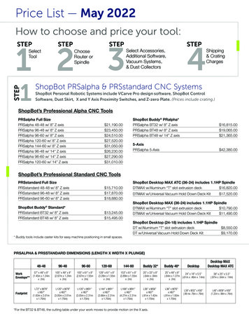
EntrepreneurshipGARAGEShopBot DesktopTabletop CNC MachineShopBot Desktop Training Guide - Entrepreneurship Garage
Entrepreneurship GARAGEShopBot Desktop CNC Training Guide - Entrepreneurship GarageRequirementsBe Certified - Training RequiredYou must complete ShopBot Certification Training before usingthe machine. By using the Entrepreneurship Garage ShopBotyou certify that you have been trained by Garage Staff andagree to abide by all rules set forth by the EntrepreneurshipGarage.UNAUTHORIZED USE WILL RESULT IN RESTRICTED ACCESSTO THE GARAGE.Be Present During OperationYou must always be present when using the ShopBot CNC, tomonitor for potential hazards! Do Not Walk Away from themachine while it is operating.Verify your CAM ToolpathBefore using the ShopBot CNC in the Garage you must ensurethat you've properly setup your CAM toolpaths. Paying closeattention to start locations, spindle speed, feed rates, chiploads, plunge depths. Also be cautious of hold down methodsand path obstructions as this can lead to dangerous scenarios.
Entrepreneurship GARAGEShopBot Desktop CNC Training Guide - Entrepreneurship GarageGuidelinesThe ShopBot Desktop is a desktop style CNC router than canaccommodate materials up to 18” x 24” in size. The ShopBotDesktop Max can be used to carve, cut, machine and mill materialssuch as wood, MDF, plastics, foams, and non-ferrous metals (likealuminum).Material Processing Area:(X x Y x Z) 24 x 18 x 3.5 inMaterialsApproved MaterialsHardwoods, Softwoods, Plywoods, Foams, PlasticsIn theory the ShopBot Desktop is capable of machining Aluminum.However, in practice, its properties and capabilities require extensiveplanning and design to mitigate associated risks. For this reason we donot machine Aluminum on the Garage ShopBot CNC.
Entrepreneurship GARAGEShopBot Desktop CNC Training Guide - Entrepreneurship GarageSafetySAFETY GEAR - EYE AND EAR PROTECTION*SAFETY GLASSES AND EAR PROTECTION ARE REQUIREDWHEN OPERATING THE SHOPBOT. Roll-up Sleeves, WearClosed Toed Shoes, Tie Hair Back and Remove all LooseJewelry.NEVER OPERATE THE SHOPBOT WITHOUT CONSTANTSUPERVISION.You must remain at the ShopBot while it's operating. Never leave theShopBot while it's operating.HIGH SPEED SPINDLE!ANY OBJECT IN THE PATH OF THE ROTATING SPINDLE/BIT WILL BECUT/EJECTED. THE MACHINE WILL NOT STOP UNLESS YOU STOP IT.NEVER PLACE YOURSELF OF OTHER UNWANTED OBJECTS IN THE PATHOF THE SPINDLE.EMERGENCY STOP!In case of Emergency use the 'spacebar' to stop the spindle. You can alsopress the 'Power Kill' button on the wall near the woodshop entrance, tokill power to all equipment in an emergency situation.TURN OFF MACHINE WHEN LOADING AND POSITIONINGAlways ensure that the machine is off when loading or positioning yourworkpiece.ENSURE ALL GUARDS ARE IN PLACE AND PROPERLYSECURED BEFORE STARTING YOUR JOB.High speed flying debirs, parts and bits pose a safety risk. Make sure thatall guards are secure and in place.ENSURE THE DUST SKIRT IS IN PLACE AND THE JET DUSTCOLLECTION SYSTEM IS ON AND OPERATING PROPERLY.Turn on the JET Dust collection system before use and make sure ductgates are open.
Entrepreneurship GARAGEShopBot Desktop CNC Training Guide - Entrepreneurship GarageFusion 360 CAD File Tutorial1. Open Fusion 3602. Hit File tab in the upper left hand corner and select “New Design”Hit Save icon inthe upper right hand corner. Name the file and choose an appropriate location3. Hit the gray arrow beside the “Document Settings” tab in the left hand side of theworkspace, and be sure that the file’s units are in Inches. This should be thedefault4. To create a sketch, hit “Create Sketch” icon just to the right of the designdropdown tab5. Select one of the three orange planes that appear on the workspace6. Now we are in “sketch mode”.7. Hit the “CREATE” dropdown and hover over “Circle”. Select “Center DiameterCircle”8. Draw a circle with a center at the origin and a radius of 2 Inches.9. To exit sketch mode, hit “FINISH SKETCH” on the far right side10. To edit a sketch, hit the gray arrow beside the “Sketches” tab in the left hand sideof the workspace11. Double-click “Sketch1”. Now we are back in sketch mode12. Now add a square that is 3”x3” centered at the origin13. Under the “MODIFY” dropdown at the top, select “Fillet” and apply to the fourcorners of the square we just sketched.14. Finish sketch15. To Extrude a sketch, select the face inside the square, but outside the circle (itshould highlight blue)16. Hit the “CREATE” dropdown and hit “Extrude”17. Drag the blue arrow until the part is 0.25 in tall. You may also type the properheight in the box. Hit enter18. This will result in a 3D part, but the sketch will turn invisible.19. To make the sketch visible, hit the eye icon beside the sketch you want to see (inthis case, Sketch1)20. Now select the circle we sketched earlier and extrude to 0.2 in21. To edit and extrusion, look for an extrusion icon on the bottom left timeline andselect the proper icon.22. Change the circle extrusion to 0.15 in23. Now our part is complete. Hide the sketches and save the file.
Entrepreneurship GARAGEShopBot Desktop CNC Training Guide - Entrepreneurship GarageFusion 360 CAD File Tutorial1. Open Fusion 3602. Hit File tab in the upper left hand corner and select “New Design”Hit Save icon inthe upper right hand corner. Name the file and choose an appropriate location3. Hit the gray arrow beside the “Document Settings” tab in the left hand side of theworkspace, and be sure that the file’s units are in Inches. This should be thedefault4. To create a sketch, hit “Create Sketch” icon just to the right of the designdropdown tab5. Select one of the three orange planes that appear on the workspace6. Now we are in “sketch mode”.7. Hit the “CREATE” dropdown and hover over “Circle”. Select “Center DiameterCircle”8. Draw a circle with a center at the origin and a radius of 2 Inches.9. To exit sketch mode, hit “FINISH SKETCH” on the far right side10. To edit a sketch, hit the gray arrow beside the “Sketches” tab in the left hand sideof the workspace11. Double-click “Sketch1”. Now we are back in sketch mode12. Now add a square that is 3”x3” centered at the origin13. Under the “MODIFY” dropdown at the top, select “Fillet” and apply to the fourcorners of the square we just sketched.14. Finish sketch15. To Extrude a sketch, select the face inside the square, but outside the circle (itshould highlight blue)16. Hit the “CREATE” dropdown and hit “Extrude”17. Drag the blue arrow until the part is 0.25 in tall. You may also type the properheight in the box. Hit enter18. This will result in a 3D part, but the sketch will turn invisible.19. To make the sketch visible, hit the eye icon beside the sketch you want to see (inthis case, Sketch1)20. Now select the circle we sketched earlier and extrude to 0.2 in21. To edit and extrusion, look for an extrusion icon on the bottom left timeline andselect the proper icon.22. Change the circle extrusion to 0.15 in23. Now our part is complete. Hide the sketches and save the file.
Entrepreneurship GARAGEShopBot Desktop CNC Training Guide - Entrepreneurship GarageShopBot Operating Instructions1. Lift the red shield on the main power switch, and switch the machine ona. Using the key, make sure that the Variable Frequency Drive unit (gray box on theside of the machine) powers on (it has a delay)2. Load the “ShopBot 3” software on the PC and wait for it to connect with the machine3. This will bring up the red position boxa. Within this box, select the yellow “keypad” icon “K Command”4. Be sure nothing is between the yellow and black tape and the ShopBot5. With the keypad active, you may use the on screen buttons to move the gantry, car,and spindle. You can also use the arrow keys on the keyboard, as well as the pageup/down keys.a. Raise the Z axis so you have access to the collet, and collet nut6. Turn the machine OFF at the red flip kill switch7. You will see two wrenches on the spoilboard. One is a blue park tool wrench (20mm),which is used to hold the spindle stationary. The other is the splined collet wrench.Using these two together, please loosen the collet nut and remove the nut and collet.You may be able to do this by hand without the wrenches.8. Our machine has ¼” and ⅜” collets, which means we can only use those sized bits9. Ensure that the collet is installed properly into the collet nut. It should seat with avery pronounced “click”10. Slide the appropriate bit fully into the collet until the top is flush with the collet.a. Ensure that none of the cutting points, flutes, etc. are pushed into the collet that’sbadb. Ensure that no more than ⅜” sticks up out of the top of the colletc. We want to be CERTAIN that at least ¾ of the bit shaft is inserted into the collet.This will prevent the bit from spinning within the collet, or the bit breaking(GOGGLES!)11. Back at the machine, ensure the threads are free of debris and clean, and handthread the collet nut onto the spindle12. Using the two wrenches, tighten the collet nut so it is hand tight, plus an additional ⅛turn. The official spec is 59ft-lbs.13. Now is a good time to position our materials on the spoilboarda. Check your T-Clamp clearance!b. Take a moment to decide where you’ll be producing your piece. Now is a greattime to measure!14. Once the bit is secured, power the main power switch back on so we can begin thezero axis procedure
Entrepreneurship GARAGEShopBot Desktop CNC Training Guide - Entrepreneurship Garage15. Zeroing the Z (every time, with every bit, with every material adjustment)a. With the gantry and the car positioned roughly near your cut, and your bitinstalled, place the Z zero plate (located in a sleeve on the left front of the machine)flat on the table under the bit.b. Take the grounding clamp, and attach it to the 20mm spindle shaft just above thecollet nut. This will allow an electrical current to flow through once the bit touchesthe plate, and the zero will be set.c. Back at the PC, close the yellow control box, and on the RED control box, you’ll seea “Z zero height” icon. Select this. The machine will load a script, and ask if you’reready to zero. With the plate flat under the bit, and the grounding clamp connectedto the spindle shaft, hit enter, and the machine will go down and touch the plate.You should see the number 1 input icon light up when it makes contact. If this doesnot happen, contact the garage manager.d. The machine should now retract the Z to .500 inches above the zero surface.e. Remove the plate, and clamp, and store them ensuring they do not touch, whichwould cause the #1 icon to light up.f. If for any reason this was unsuccessful, consider the machine INOP, and contactthe garage manager.16. Zeroing the X and Y axisa. Select the “X & Y Zero” Icon on the red control panelb. The machine will use the limit switches to calibrate.c. Select OK afterwards17. Raise your Z and attach the dust foot.18. Next we need to warm the bearings in the spindle up to operating temperature.a. Adjust the VFD to approximately “100” which equals roughly 6000 RPM. This shouldrun for approximately ten minutes to properly warm the bearings up to operatingtemperature. So please note the time.b. Install the front plexi shieldc. Open the yellow control box, and select the “#1 Output” blue icon. This WILLactivate the spindle.19. While the bearings are spinning up to operating temperature, let’s work on our design!See the Fusion 360 CAD and CAM tutorial on pages 3 and 420. After ten minutes, adjust the VFD slowly to read approximately “300” which will be 18000RPM. You should hear the speed audibly change as you increase the RPMa. Select the “#1 Output” icon again to turn off the spindle
Entrepreneurship GARAGEShopBot Desktop CNC Training Guide - Entrepreneurship Garage21. With the bearings fully up to operating temperature, it’s time to run a Part File!a. First we should run our Part File in “Preview” modei. Exit out of the yellow control boxii. Select “Preview Part” button on red position boxiii. Choose file from file exploreriv. To change any cutting parameters or settings, select “Set File Parameters”button in red position boxv. Hit “Start” button in red position box1. This is the path that you have programmed into the tool.2. Red lines indicate travel moves3. Blue lines indicate cutting movesvi. Observe this file in 3D, and expand the “Material” tab on the left to find anyerrors1. Check material thickness, and orientation for Z22. Select the “Toolpaths” tab on the lefta. Ensure that the “Table”, “Material”, and “Origin” boxes are checked, and CONFIRMthat these make sense. Click them on and off to be sure.b. Select “Preview Cut” to ensure your finished (digital) model matches what you’d liketo have in real life23. Now that the sample looks good, we can switch to “move/cut mode” by selecting the“Cut Part” button in the red position box24. From here, we should run an “air cut” to be certain the machine does what we wantbefore actually cutting the material.a. Air-cutting allows us to run our actual toolpaths with the machine zeroed adistance ABOVE our material. This is an excellent way to ensure that the machinehas interpreted your toolpaths correctly.b. To do this, we should run a “K Command” and raise our Z to a specific(appropriate) heightc. We can now set this as our zero position by typing a letter “O” command and a “Z”command and hit enterd. ESC out of the yellow control box25. Press “Cut Part” button and load the same file as done beforea. Ensure our safety shielding is in placeb. Safety glasses and ear protection are mandatoryc. The machine will ask if the correct tool is in the spindled. The machine will ask if the Z axis is zeroede. This will ask you to select “OK” to run your PartFile. THIS WILL START MOVING THEMACHINEf. When the PartFile is done running, the machine will ask you to hit “OK” toacknowledge completion of the cut
Entrepreneurship GARAGEShopBot Desktop CNC Training Guide - Entrepreneurship Garage26. Now to make our actual cut, re-zero the Z axis using the touch plate as described in Step1527. Press “Cut Part” button and load the same file with the newly corrected Z axis28. The machine will ask you if it’s ok to start the spindle and run the PartFile29. THIS WILL BEGIN YOUR ACTUAL CUT!!!!!a. Ensure all safety measures are in placeb. Ensure that our two primary environmental controls are active. Check that the JETAir filtration vent behind the ShopBot is fully open (Both Grizzly Dust Extractor, andJET Air Filtration)c. Select "OK"30. Select “OK” to acknowledge the completion of the cut31. We should inspect our work before we remove the stock to ensure we don’t need tomake any adjustments32. Once we’re sure our work is satisfactory, we can position the gantry and car in a positionthat will allow us to easily remove the bit, and our work33. Power the machine off at the VFD and the main red kill-switcha. Remove the bit, and reinstall the collet, and collet nutb. Once the bit is safely stored, remove your materials, tidy up and log your time
Open Fusion 360 Hit File tab in the upper left hand corner and select "New Design"Hit Save icon in the upper right hand corner. Name the file and choose an appropriate location Hit the gray arrow beside the "Document Settings" tab in the left hand side of the workspace, and be sure that the file's units are in Inches. This should be .