Transcription
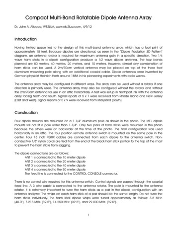
Compact Multi-Band Rotatable Dipole Antenna ArrayDr. John A. Allocca, WB2LUA, www.wb2lua.com, 4/9/12IntroductionHaving limited space led to the design of this multi-band antenna array, which has a foot print ofapproximately 15 feet. Because dipoles are directional, as seen in the “Dipole Radiation 3D Pattern”diagram, an antenna rotator is required for maximum antenna gain in a specific direction. Two 1/4wave ham sticks in a dipole configuration produce a 1/2 wave dipole antenna. The four bandsplanned are 80 meters, 40 meters, 20 meters, and 10 meters. However, almost any combination ofham sticks can be used. A 2m/70cm vertical antenna may be placed on top of the three footaluminum mounting pole along with an additional coaxial cable. Dipole antennas were invented byGerman physicist Heinrich Hertz around 1886 in his pioneering experiments with radio waves.The antenna array may be configured in different ways. The array can be used without a rotator if onedirection is primarily used. The antenna array may also be configured without the rotator and withoutthe 2m/70cm antenna for use in an attic horizontally. A test was setup in Northport, NY with the antennaarray facing North and South. Signal reports of 5 x 7 were received from Rhode Island and New Jersey(East and West). Signal reports of 5 x 9 were received from Maryland (South).ConstructionFour dipole mounts are mounted on a 1-1/4” aluminum pole as shown in the photo. The MFJ dipolemounts will not fit a pole wider than 1-1/4”. Only two pairs of ham sticks were mounted in this photobecause the others were on backorder at the time of the photo. The final configuration was usedhorizontally in an attic. The four position remote antenna switch is mounted on the same pole in thecenter. Four 18 inch RG8X cables are connected from each dipole to the antenna switch. Nonconductive 1/8” nylon cords are tied from the end of the black ham stick portion to the top of the mastto prevent the ham sticks from sagging.The dipole connections are as follows:ANT 1 is connected to the 10 meter dipoleANT 2 is connected to the 20 meter dipoleANT 3 is connected to the 40 meter dipoleANT 4 is connected to the 80 meter dipole.The feed line is connected to the CONTROL CONSOLE connector.There is no control wire required for this antenna switch. Control signals are passed through the coaxialfeed line. A 3 wire cable is connected to the antenna rotator. The pole is mounted to the antennarotator. It is extremely important to tune the ham sticks as a pair in the dipole configuration with anantenna analyzer. The whips on each ham stick of a pair should be the same length. Do not tune theham sticks individually. The ham stick dipole whips were tuned approximately as follows: 3.8 MHz.(40.0”), 7.213 MHz. (39.5”), 14.250 MHz. (39.5”), and 29.000 MHz. (39.0”).1
The radiation pattern above is not to scale. The dipole antenna is 15 feet wide. The radiation pattern ishundreds and thousands of miles.Near Vertical Incidence Sky Wave (NVIS)NVIS propagation is a propagation pattern that uses antennas with high-angle radiation (almost 90degrees, vertical) and low operating frequencies. The primary range is about 0-300 miles. The patternmay extend beyond 300 miles depending antenna height and upon environmental conditions.Long distance propagation uses radio waves that are reflected from the ionosphere and return to earthat some distance away. Radio waves that are radiated at a very low angle, travel a long distance toreach the ionosphere at a very shallow angle and return to earth far away. When the angle of radiationincreases, the radio waves reach the ionosphere at a greater angle, and return to earth closer to theirpoint of origin. Signals that reach the ionosphere at a higher angle of incidence will not be reflected atall, but will continue out into space. The area of reflection that would have occurred is the "skip zone".Depending on operating frequencies, antennas, and propagation conditions, this skip zone can start atroughly 12 to 18 miles and extend out to several hundred miles, preventing communications.NVIS antennas are designed to minimize the ground wave (low takeoff angle) radiation and maximizethe sky wave (very high takeoff angle, 60-90 degrees). Essentially, the NVIS antenna radiates a wavealmost straight up, then bounces from the ionosphere and returns to the Earth in a circular patternaround the transmitter. Because of the near-vertical radiation angle, there is no skip zone.Communications are continuous out to several hundred miles from the transmitter. The nearly verticalangle of radiation requires the use of lower frequencies, usually 2-10 MHz. This type of propagation isexcellent when communicating over hills and mountains. These frequencies are the same frequenciesthat contain a lot of atmospheric noise, such as distant thunderstorms. The NVIS antenna is optimized forlistening to signals from nearby areas, and minimizes the reception of signals from distant sources.2
One of the most effective antennas for NVIS is a dipole that is mounted from 0.1 to 0.25 wavelengthsabove ground. When a dipole is brought very close two ground, the angle of radiation increases. In therange of 0.1 to 0.25 wavelengths above ground, vertical and nearly vertical radiation reaches amaximum. A dipole can be used at even lower heights, resulting in some loss of vertical gain, but often,a more substantial reduction in noise and interference from distant regions. Heights of 5 to 10 feetabove ground are not unusual for NVIS operation.During a test by WOIPL, they used a 75-meter dipole at a height of 30 feet. They found thecommunications to be difficult. They set up a second dipole at a height of 8 feet. The backgroundnoise went from S7 to S3 and the communications with stations 25 miles and further, greatly improved.Many people find the 10 to 15 foot height to be ideal. Field tests have proven that the maximum NVISefficiency is obtained at the 10 to 15 foot height for frequencies in the 40 meter to 75 meter range.RACES within uses 80 meters for NVIS communications within a state.Full Wavelength Antennas:Frequency (MHz.)Wavelength (L) (m)1.9157.93.878.95.356.67.241.70.1L (m)15.87.95.74.80.25L (m)39.519.714.210.0.1L (ft)51.825.918.715.70.25L (ft)129.664.643.334.11/2 Wavelength Antennas:Frequency (MHz.)Wavelength (L) (m)1.9157.93.878.95.356.67.241.70.1L (m)7.94.02.92.40.25L (m)19.75107.2560.1L (ft)25.913.09.47.90.25L (ft)64.832.523.519.81/4 Wavelength Antennas:Frequency (MHz.)Wavelength (L) (m)1.9157.93.878.95.356.67.241.70.1L (m)4.02.01.41.20.25L (m)105.03.53.00.1L (ft)13.06.54.73.90.25L (ft)32.516.311.89.83
Photo4
Parts ListFour MFJ-347 3/8-24, Double T Pipe Mount, with SO-239, 19.95 x 4 79.80Channel Master RC Antenna Rotator System, Model: CM-9521A, 99.99, Radio Shack 3977724100-Ft. Rotator Control Cable, Model: 15-1150, 24.95, Radio Shack 2049616(2) 75m MFJ Ham sticks, 19.99 each x 2 39.98(2) 40m MFJ Ham sticks, 14.95 each x 2 29.90(2) 20m MFJ Ham sticks, 14.95 each x 2 29.90(2) 10m MFJ Ham sticks, 14.95 each x 2 29.90Aluminum Tubing, 1-1/4" OD, 1.084" ID, .083" Wall Thickness, 3' L, 35.80, McMaster-Carr 9056K772UHF Male to UHF Female Right Angle adapter, 9.00Ameritron RCS-4, remote antenna switch, 149.95Cable Experts CXP08XC18INCH, 18 inch RG8X cable with PL-259 connectors, 17.95 x 4 ---------------------------------------------Total 600.97Extras if needed:20 foot Antenna Mast Antennacraft 10-Ft. 16-Gauge Mast, Radio Shack Catalog #: 15-298, 29.99 x 2 59.98Cable Experts CXP08XC100, 100 feet RG8X cable with PL-259 connectors, 54.95Mounting bracketsPortable Mast and Tripod:Use 4 sections of the 1-1/4” OD, 3 feet aluminum tubing. Cut the 1-3/8” OD tubing into three 12 inchsections. Position the 12” sections over the joint of two of the 3 feet sections. Drill through the twosections with 5/16” holes and use 1/4-20 screws, washers, lock washers, and hex nuts to join the sections.Insert the end of the assembled 4 sections into the PA speaker stand. Two 6 foot 1-1/4” OD sections canalso be used in place of the 4 three foot sections.Aluminum Tubing, 1-1/4" OD, 1.084" ID, .083" Wall Thickness, 3' L, 35.80, McMaster-Carr 9056K772Aluminum Tubing, 1-3/8" OD, 1.259" ID, .058" Wall Thickness, 3' L, 29.59, McMaster-Carr 89965K415PA speaker stand that uses 1-1/4 OD tubing available from most musical instrument stores5
Having limited space led to the design of this multi-band antenna array, which has a foot print of approximately 15 feet. Because dipoles are directional, as seen in the “Dipole Radiation 3D Pattern” diagram, an antenna rotator is required for maximum antenna gain in a specific direction. Two 1/4 wave ham sticks in a dipole configuration produce a 1/2 wave dipole antenna. The four bands .