Transcription
PNNL-SA-88359Building Re-Tuning Training Guide: AHU Heating and CoolingControlSummaryThe purpose of the air-handling unit (AHU) heating and cooling control guide is to show,through examples of good and bad operations, how AHU heating and cooling can be efficientlycontrolled.AHU heating and cooling coils are generally located in the discharge-air stream, immediatelydownstream of the mixing plenum and filters, to provide heating or cooling. On some AHUs,the cooling coil will also be used to de-humidify the air stream. This may require the heatingcoil to be located downstream of the cooling coil for climates where de-humidification isrequired. It is also possible that a secondary heating coil in the AHU is located in thedownstream side of the supply fan or cooling coil. The purpose of this secondary heating coil isto add additional heat to the air stream in cold climate zones, or climate zones where dehumidification is required. By monitoring the outdoor-air temperature and heating- andcooling-coil-valve signals over time, the building operator can identify times when the AHU issimultaneously heating and cooling the discharge-air stream, and make adjustments to AHUoperation. If the outdoor-air temperature heating lockout set point is lower than the outdoorair cooling lockout set point, this may be indicative of a leaking heating and/or cooling-coilvalve.Inefficient operation of heating and cooling coils, such as leaky valves, incorrect outdoor-airtemperature lockout set points for heating and cooling, poor heating and cooling control suchas hunting and overheating and overcooling, and simultaneous heating and cooling, if notcorrected, in all likelihood will lead to increased fan, heating and cooling energy consumption.Data needed to verify AHU heating and cooling controlTo analyze and detect deficiencies in AHU heating and cooling control, for single-duct variableair-volume (SDVAV) AHU(s), the following parameters must be monitored using the trendingcapabilities of the building automation system (BAS): Outdoor-air temperature (OAT) Cooling-coil-valve signal (CCV) Heating-coil-valve signal (HCV)1
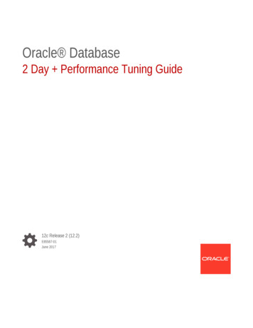
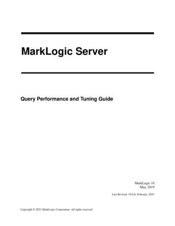
PNNL-SA-88359The recommended frequency of data collection is between 5 and 30 minutes. When analyzingheating and cooling control of the AHU, the trends to look for include: Are outdoor-air temperature lockout set points for heating and cooling reasonable, dothey overlap? Is there simultaneous heating and cooling occurring?Are outdoor-air temperature lockout set points for heating and cooling reasonable, do theyoverlap?Outdoor-air temperature lockout set points for heating and cooling are critical to preventadditional energy consumption that otherwise is not needed. The balance point of the building,i.e., when the building needs neither heating nor cooling, is critical when setting these lockoutset points. In general, the heating should be locked out above 50oF or the lowest outdoor-airtemperature that the building can maintain the discharge-air without requiring heat1. Coolingshould be locked out below 55oF or the highest outdoor-air temperature that the building canmaintain the discharge-air without requiring cooling. These set points should be checked toensure that they are not backwards, i.e., the cooling lockout is lower than the heating lockout.There should be no overlap between these set points at any time. The goal is to lockout coolingduring the winter season, and heating during the summer season.Suggested ActionsCheck the building automation system’s (BAS) control logic for accuracy of heating and coolinglockout set points. Make sure that these lockout set points do not overlap. If the outdoor-airtemperature heating lockout set point is lower than the outdoor-air cooling lockout set point,check the heating and cooling-coil valves for leaks.Is there simultaneous heating and cooling occurring?The goal is to avoid simultaneous heating and cooling from occurring in the AHU. Somesimultaneous heating and cooling can be unavoidable in climate zones where dehumidificationis required. The goal is to minimize the amount of heating and cooling occurringsimultaneously, and to lock out heating or cooling coils whenever possible. Figure 1 below is aguideline for AHU heating- and cooling-coil-valve signals relative to one another.1For some buildings (museums or library) where the AHU provides dehumidification, heating may be required athigher outdoor temperatures.2
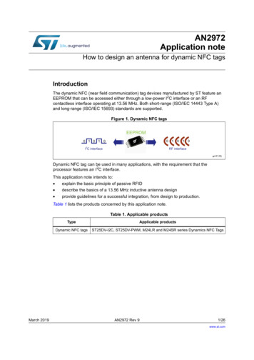
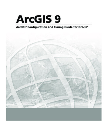
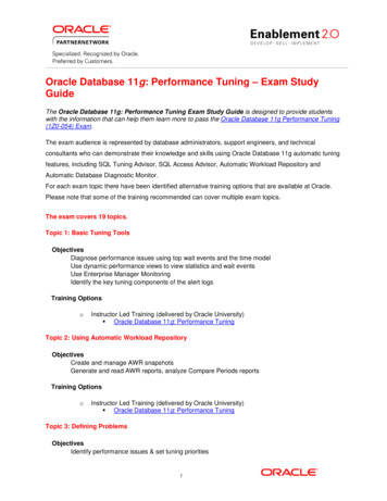
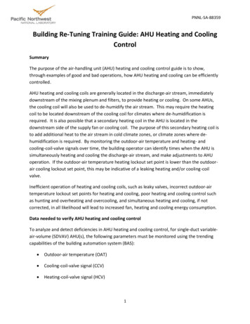
PNNL-SA-88359Figure 1: AHU heating and cooling valve positions.The data in Figure 1 shows that the heating has been locked out (the hot-water valve is alwaysat 0% while the chilled-water valve modulates). This would correspond to summertimeoperation, in which the outdoor-air temperature is always greater than 50oF.When monitoring simultaneous heating and cooling, analyze the heating-coil valve, cooling-coilvalve, and outdoor-air temperature versus time charts. Figure 2 below shows this chart for a 2day period in November. As you can see, the outdoor-air temperature never gets above 30oF,yet the cooling-coil valve is always 75% open. The heating coil appears to be 50% open duringoccupied hours, and then shuts off during the unoccupied periods. The amount of heatingrequired to meet the discharge-air temperature set point would decrease if the cooling coil waslocked when the outdoor-air temperatures are low. This is an example of bad operation.Figure 3 shows an example of good operation, where the same 2-day period in Novembershows the cooling-coil valve locked out. As a result, the heating-coil valve position has droppedfrom roughly 50% in Figure 2 to 25% in Figure 3 during occupied hours.3
PNNL-SA-88359Figure 2: Simultaneous heating and cooling during the winter season.Figure 3: Cooling-coil valve locked out during winter season.4
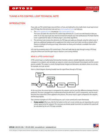
PNNL-SA-88359Figure 4 shows another example of good operation. The outdoor-air temperature variesbetween 50 and 60oF during this 2-day span in November. The heating-coil valve never opens,and the cooling-coil valve modulates during occupied hours to maintain the discharge-airtemperature set point.Figure 4: Heating-coil valve closed during AHU cooling mode.Suggested ActionsIf the plot of the cooling-coil valve, heating-coil valve, and outdoor-air temperature versus timeshows simultaneous heating and cooling, check to make sure the coils are clean and that thevalves are not leaking. To check the cooling coil for leaks, touch the cooling coil where itpenetrates the AHU. If the pipe is colder than room temperature, then this indicates that thevalve is leaking (perform the same check on the heating coil). Additionally, If condensate isobserved on uninsulated lines or exposed coil sections during times when mechanical cooling isnot being called for by the control system or during times when the outdoor-air conditionsshould be adequate for economizing, then leaking cooling-coil valves should be suspected.5
simultaneous heating and cooling can be unavoidable in climate zones where dehumidification is required. The goal is to minimize the amount of heating and cooling occurring simultaneously, and to lock out heating or cooling coils whenever possible. Figure 1 below is a guideline for AHU heating- and cooling-coil-valve signals relative to one .