Transcription
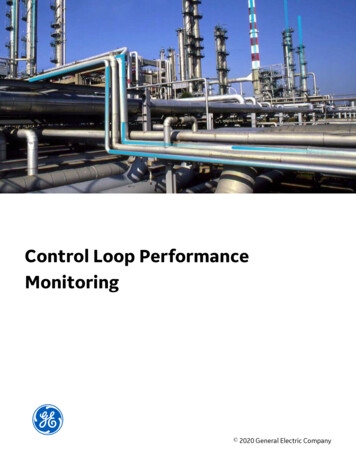
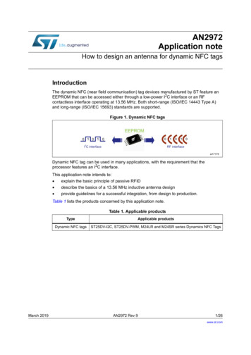
TECHNICAL NOTEForm 2171-200731PAGE 1TUNING A PID CONTROL LOOP TECHNICAL NOTEINTRODUCTIONIf you only use PID control loops now and then, or if you are looking for a less-math-more-visual way to tuneyour PID loop, then this technical note and our online graphical tuner can help you. The online graphical tuner is located at: http://www.opto22.com.The tuner calculates the values for PID control loop elements (P, I, D, and scan rate) based on data youenter. It’s an easy way to get very close to functional tuning for your real-world process PID. Note that thetuner is optimized for Opto 22’s Velocity Type C and similar algorithms. This technical note reviews the elements of a PID loop and walks you through using the online tuner. Itgives you additional background to supplement the online tuner, but it does not discuss details of thetheory or methods of tuning your loop. (Information on theory and methods is available from othersources online.)Let’s start by reviewing what a PID control loop is. Then we’ll walk step by step through tuning a PID loopusing the online tuner and the open-loop or reaction curve tuning method.What is a PID control loop?A PID control loop is a mathematical formula that monitors a process variable (typically a sensor input),compares it to a setpoint, and calculates an output to correct any error between that setpoint and the currentprocess variable. The output is a result of proportional, integral, and derivative calculations done at a set rate,for example, once per second.Here is a block diagram showing broadly how the signal flows through a PID loop.SensorinputScan rateSetpoint or Error–?PIDformulaOutputProcessAt the scan time, the sensor input is compared to the setpoint, and an error (the difference between them) isproduced. This error is plugged into a mathematical formula with the P, I, and D components, and the resultbecomes the output that is then applied to the process. The sensor input is again compared to the setpoint,and the loop repeats.Two common examples of a PID control loop are a car’s cruise control and a room thermostat. Cruise control. When you click the Set button on the car’s cruise control, you are requesting the currentvehicle speed to be the setpoint. The necessary accelerator pedal movement to maintain this speed willbe calculated by the car’s PID loop controller.OPTO 22 800-321-6786 1-951-695-3000 www.opto22.com sales@opto22.com 2015-2020 Opto 22. All rights reserved. Dimensions and specifications are subject to change. Brand or product names used herein are trademarks or registered trademarks of their respective companies or organizations.
Tuning a PID Control Loop Technical NoteForm 2171-200731PAGE 2The loop controller measures the vehicle road speed, determines the positive or negative error from thesetpoint, and sees how quickly it is approaching or departing from that setpoint. The result is that eithermore or less accelerator is applied to the engine. Room thermostat. In the case of the room thermostat, the temperature is measured and compared tothe desired setpoint. Either heating or cooling will be activated, depending on the sign of the error.Tuning the loopTo be most effective, each PID loop must be tuned. Tuning makes sure that the PID output (the controlledvariable) moves the PID input (the process variable) to the desired setpoint as quickly as possible withminimum overshoot, and then holds that setpoint steady with minimal changes in the output.In the case of the car’s cruise control, we want to make sure the speed does not vary around the setpoint,because if it does, the car’s occupants could get motion sickness when the car constantly speeds up and slowsdown. In the case of the room thermostat, we do not want the room temperature to swing around thesetpoint, as the occupants will be uncomfortable as they switch from feeling too cool to feeling too warm.Tuning solves these problems.Before we dive into tuning the loop, let’s take a moment to review a few of the key parts of the PID loop.ProportionalThe proportional component of the PID calculation (sometimes called gain or error term) looks only at thedifference between the setpoint and the process variable (input). The output signal is a proportional responseto this error. Depending on the formula used in the PID controller, increasing the proportional value will speedup the response of the PID loop. Excessive values will put the process into oscillation; even larger values couldcause the system to oscillate out of control.OPTO 22 800-321-6786 1-951-695-3000 www.opto22.com sales@opto22.com 2015-2020 Opto 22. All rights reserved. Dimensions and specifications are subject to change. Brand or product names used herein are trademarks or registered trademarks of their respective companies or organizations.
Tuning a PID Control Loop Technical NoteForm 2171-200731PAGE 3IntegralThe integral component sums the output error over time. The integral value is linked to the scan rate of the PIDloop. The function of the integral value is to reduce the steady state error to zero. An effect called integralwindup can occur when the value of the integral saturates the PID controller and the error signal cannot bedriven to zero.Some PID formulas use an inverted integral.DerivativeThe derivative component looks at the rate of change in the output and reduces that rate of change if theoutput moves too fast. Increasing this value will cause the output to react in very small increments; ifincrements are too small, the derivative can cause the loop to become sensitive to noise. Often loops can betuned satisfactorily with no derivative at all.Direction of outputDepending on the nature of the process, the direction of output may be the same as or opposite to thedirection of the input. You’ll need to make sure the output direction is correct for your application. In some applications the direction of output is the same as the direction of input (increment/increment,or decrement/decrement). In others, the direction of output is the opposite of the direction of input (increment/decrement, or viceversa). This is called a reverse acting PID control loop.In the case of our car cruise control, we need to make sure that when the vehicle approaches a hill and theroad speed drops below the setpoint, the PID loop directs the accelerator to apply more power to the engine.In this case, a decrement in the input (road speed) causes an increment to the output (accelerator).In the case of our heating/cooling system, the thermostat provides the input (the controlled variable) astemperature. There are two PID loop controllers, one for the heating valve and one for the cooling valve.Each has a different setpoint, to ensure that you do not have both valves open at the same time.In the case of heating, an increase in the room temperature means the PID needs to close the heating valve.Less heating water flows through the valve, so the room cools down. This is an increment on the input thatcauses a decrement on the output. In the case of cooling, the same increase in room temperature needs tocause an increment in the cooling water valve; this is an increment on the input causing an increment onthe output.PID controllers have different ways of changing the direction of output. Check your PID loop manual orformula to determine the correct way to set the output direction.Loop dead timeThe amount of time it takes the process to react to a change in the input is called the loop dead time. This timedelay is a combination of factors, starting with the process itself, the location of the sensors, and any filtering(hardware or software) that may be installed.For example, moving the temperature sensor physically closer to the output actuator may reduce the loopdead time, but you must take care that the sensor still measures the process accurately. You have to find abalance between the loop dead time and accuracy.Scan rateHow often the PID calculation is performed is called the scan rate, and scan rate is a very important aspect ofconfiguring the PID loop. If the formula is performed too seldom, you won’t be able to control the process; ifperformed too frequently, the loop might be hard to tune.OPTO 22 800-321-6786 1-951-695-3000 www.opto22.com sales@opto22.com 2015-2020 Opto 22. All rights reserved. Dimensions and specifications are subject to change. Brand or product names used herein are trademarks or registered trademarks of their respective companies or organizations.
Tuning a PID Control Loop Technical NoteForm 2171-200731PAGE 4Generally the PID scan rate should be at least four times faster than the loop dead time, but it can be as highas 10 times faster. The shorter the loop dead time, the faster your scan rate should be.At all times keep in mind the speed limits, if any, of your input and output devices, both sensors and actuators.There’s no point in scanning faster than they can update.Since the PID calculation is only performed at the scan rate, be aware that the output will remain static untilthe next scan. This is why it’s important to correctly set the scan rate period, so the output will react to theinput in a timely manner.PID tuning methodsP and PI tuning P tuning—It is possible to “tune” a process using just the proportional value. The problem is that therewill be a steady state offset between the process variable and the setpoint. The process will simply neverreach the setpoint—but it will be under control.PI tuning—Some PID loop controllers only offer the option of PI (proportional and integral) tuning.The addition of the integral value removes the steady state offset and ensures that the process settles onthe setpoint (once the controller is tuned correctly).PID tuningComplete PID tuning is the best way and the usual offering of most PID controllers. The addition of thederivative ensures that the loop is not too overly reactive during any sudden process or setpoint changes.There are several methods for complete PID tuning. Arguably the most popular are trial and error, reactioncurve closed loop (sometimes called infinite oscillation), and reaction curve open loop (sometimes calledstep response).For obvious reasons we don’t recommend trial and error. Your time is too valuable for that.The reaction curve closed-loop method is a possibility, but it requires putting the process into a state ofoscillation. If not done with a great deal of care, it can easily result in the process being damaged by theoscillations.So for this technical note and the online tutorial, we’re using the reaction curve open loop method, specificallythe Ziegler-Nichols Reaction Curve (Ziegler-Nichols Open-Loop) tuning method. This method works well forOpto 22 Velocity Type C and similar algorithms.This method can be trial-run several times, starting with very small steps in output, thus keeping the processunder control while observing the changes in the steps. For most processes, this is a safer method ofdetermining the required tuning parameters.TUNING A LOOP USING THE ZIEGLER-NICHOLS OPEN-LOOP METHODHere are some limitations to be aware of when using this method of tuning. First, the process response time should be around twice the loop dead time. In other words, this methodworks well to tune most temperature and some pressure processes, but it will not be as useful on slowerflow or very dynamic processes, for example a process where the dead loop and response curve aresimilar in length. Likewise it will be less effective if you have a very long loop dead time, for exampleHVAC in a large conference room or hall. Second, depending on your PID loop controller formula, you may need to invert the integral value that iscalculated for you. Check your formula or manual for that information.OPTO 22 800-321-6786 1-951-695-3000 www.opto22.com sales@opto22.com 2015-2020 Opto 22. All rights reserved. Dimensions and specifications are subject to change. Brand or product names used herein are trademarks or registered trademarks of their respective companies or organizations.
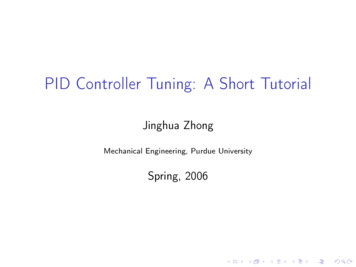
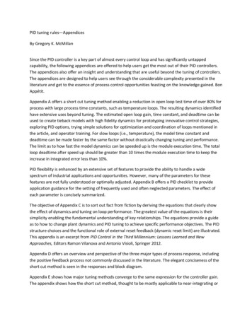
Tuning a PID Control Loop Technical NoteForm 2171-200731PAGE 5 Third, an important part of the tuning method is that the process must self-stabilize for a given change inoutput.And last, critical to this tuning method is that your loop controller software is capable of producing agraph similar to the one below, so you can print out or take a screenshot of the output (controlledvariable) step change with the resulting input (process variable) curve.Using the online tuner to tune your PID control loopTuning PID control loops is not easy, and you must calculate each loop individually. But our online graphicalPID tuner gives you an easier way to calculate a functional loop.Start by opening a web browser and navigating to: http://www.opto22.comOPTO 22 800-321-6786 1-951-695-3000 www.opto22.com sales@opto22.com 2015-2020 Opto 22. All rights reserved. Dimensions and specifications are subject to change. Brand or product names used herein are trademarks or registered trademarks of their respective companies or organizations.
Tuning a PID Control Loop Technical NoteForm 2171-200731PAGE 6In the tunerYou’ll notice that the first three black or red buttons at the top of the tuner very briefly cover the backgroundthat this paper covers in more detail.The last eight red buttons are the steps you’ll follow to enter values from your process and have the tunercalculate P, I, D, and scan rate for your loop.Tuning procedureIf you already have some rough tuning values for your PID loop, make a note of them. If not, don’t worry; westart with the loop in manual. In either case the procedure is the same: we step the process from one steadystate to a higher steady state, and capture the curve of the process in a graph that can be printed out onpaper.Use the first step in the tuner as a guide for the response curve graph that you require. If the curve of theprocess overruns the time scale of your graph the first time, reset the process, extend the time scale, andstep the process again. Or if the process is very responsive and the resulting curve is too compact to measure,reset the process and speed up the graph.You may need to take a few trial runs at generating a nice clean curve on paper, but as you gain experience inperforming this tuning method, you will be faster at getting it right the first time.Follow the steps1.2.3.4.5.6.Click the red Step 1 button. Put the PID loop into manual and set the output to a nonzero value.You may need to test this a few times to see what a good low output value is. Again,do not use zero. Try to use a value of at least 10%. For example, with HVAC try a value around 20%.Wait for the process to settle into a steady state. In the tuner, enter the control variable lower and uppervalues—that is, the output value that you stepped from and the value you stepped to.Watch the controlled variable react to that step change in the process, and wait for the process to settleinto a steady state. In the tuner, click the red Step 2 button and enter the upper and lower values of thecontrolled variable.Remember, you need to wait till the process has settled into a steady state. Use the image in the tuner asa guide of how the curve should look.Click the Step 3 button in the tuner. On your printout, measure the distance between the lower steadystate of the controlled variable and upper steady state. Enter the distance between the two states intothe tuner.The amount of change in the controlled variable as a result of the step change is used to calculate the Por gain term. Hint: while not required, you may find it easier to use millimeters rather than decimal inchesas the distance units.Click the Step 4 button. Press the button in the tuner to have it calculate the 63.2% point on the curve.The answer is given in a height from the lower steady state. Measure this height on your printout andmark the point on the curve. Drop a vertical line down from this point on the curve.Click Step 5. Measure on your printout how long it took the process to change from its lower steady stateto the 63.2% point on the curve. In the tuner, enter the distance you measured.This distance will be converted to time in the next step so that we can determine the loop time constant.This is the amount of time that it took the input to move from its lower steady state to the 63.2% point ofthe input curve. This time tells us how dynamic the process is and is an important part of the Integralvalue calculation.Click Step 6. On your graph, measure the distance between two known points of time. In the tuner, enterthe time (in seconds) from the graph and enter the distance you measured.Again, while not required, you may find it easier to use millimeters rather than decimal inches as thedistance units.OPTO 22 800-321-6786 1-951-695-3000 www.opto22.com sales@opto22.com 2015-2020 Opto 22. All rights reserved. Dimensions and specifications are subject to change. Brand or product names used herein are trademarks or registered trademarks of their respective companies or organizations.
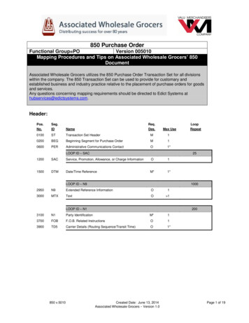
Tuning a PID Control Loop Technical NoteForm 2171-200731PAGE 77.8.Click Step 7. To help calculate the PID controller scan rate, measure the distance between the stepchange in the output and the change in the input.This is the process loop dead time, that is, the amount of time it takes the process to react to a change.Dead time is an important part of understanding how frequently you should set the PID controller toperform its loop calculation. The online tuner calculates a scan rate that is four times faster than the loopdead time you enter. See “Scan rate” on page 3.Click Step 8. Press the “Calculate tuning” button and write down the results.The tuner now has all the data it needs to calculate the P, I and D values for you and to suggest a scanrate. If you want to understand the process that the tuner uses to compute those numbers, check the“Show calculation” box.Suggested scan rate(4x the loop dead time)Calculated valuesfor P, I, and DCheck this box to show thetuner’s calculationsTuner’s calculationsOPTO 22 800-321-6786 1-951-695-3000 www.opto22.com sales@opto22.com 2015-2020 Opto 22. All rights reserved. Dimensions and specifications are subject to change. Brand or product names used herein are trademarks or registered trademarks of their respective companies or organizations.
Tuning a PID Control Loop Technical NoteForm 2171-200731PAGE 8Keep in mind that these numbers may still need some fine tuning; but since they are derived from theprocess itself, they should be very close to functional.ADDITIONAL RESOURCESThis technical note provided a brief review of the major parts of a PID control loop, looked at one method togather the necessary data from the process, and walked you through using our online graphical tuner tocalculate the P, I, and D terms and scan rate to bring a process under control using a PID loop.Here is some additional information online you may find helpful: Reaction curve tuning example from the Wisconsin Technical College System mple Animated graphic that shows what happens when you adjust the P, I, and D terms in your PID controlloop: https://en.wikipedia.org/wiki/PID controller#/media/File:PID Compensation Animated.gifOpto 22 PID loop controlOpto 22 provides two basic ways to do PID loop control. In your control program—You can configure and graphically tune PID control loops while developingyour control program in PAC Control software. Your program runs on a SNAP PAC standalone,rack-mounted, or PC-based programmable automation controller. On an I/O processor (brain)—If you are using a different PAC or a PLC, you can use the 96 built-in PIDloops available in all SNAP PAC I/O processors (brains) to provide distributed intelligence. Your PID controlloop continues to run locally even if communications with the controller are lost.In both cases you’re using reliable Opto 22 SNAP I/O for connections to field devices. Analog and digital SNAPI/O modules come in a wide variety of signal types, with 2 to 32 I/O points individually configurable fordifferent signals. Each module is tested—twice—before it leaves our factory and headquarters in Temecula,California. Most I/O modules are guaranteed for life.Product support on all Opto 22 products is free and provided by experienced engineers in our Californiaheadquarters.For more information on Opto22 PID loops, see the following resources: Basic information on PID loop control and Opto 22’s options for PIDs OptoForum post with a wealth of detailed information on using PIDs in PAC Control Tutorial on PID loops designed for use with a SNAP PAC Learning Center, a self-contained system ofhardware, software, sensors, and actuators for learning about automation and the SNAP PAC System.For more information about Opto 22 and automation products, visit opto22.com or contact our Pre-salesEngineers online or by phone: 800-321-6786 (toll-free in the U.S. and Canada) or1 951-695-3000OPTO 22 800-321-6786 1-951-695-3000 www.opto22.com sales@opto22.com 2015-2020 Opto 22. All rights reserved. Dimensions and specifications are subject to change. Brand or product names used herein are trademarks or registered trademarks of their respective companies or organizations.
PID tuning Complete PID tuning is the best way and the usual offering of most PID controllers. The addition of the derivative ensures that the loop is not too overly reactive during any sudden process or setpoint changes. There are several methods for complete PID tuning. Arguably the most popular are trial and error, reaction