Transcription
User Manualof32*16 LED Matrix Panel White(AD026)This provides step by step approach to driving a Dot Matrix Display (DMD) Panel with an Arduino. The DMD is a512 pixels single colour LED display arranged in 32x16 layout, a 16 pin (2x8) IDC connector is used to interfacewith Arduino.In order to drive the 32x16 Dot Matrix Display Panel from Arduino, the DMD library for Arduino isrequired.The Freetronics DMD library is able to write letter and text on the display board with limitedfunction, variable string and text centering is not supported. Yeah! now you can use my code to writevariable string on the display board and centering it horizontally.www.openplatform.cc
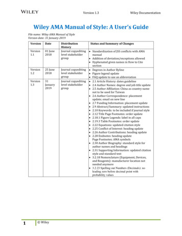
Pinoutwww.openplatform.cc
OE - Enable / Disable ALL the LEDs on the DMDA - pins select which 1/4 of the DMD is selectedB - pins select which 1/4 of the DMD is selectedC - pins select which 1/4 of the DMD is selectedD - pins select which 1/4 of the DMD is selectedCLK - Used to clock each pixel into the DMD shift registersSCLK - Latches the current content of the DMD shift registersR - The raw pixel data stream (NB: The 'R' stands for RED. You might notice an unused 'G' pin which is forGreen on a HUB12 connector)Library installationThe Freetronics DMD library must work together with TimerOne library, the TimerOne library is availablehere.Install TimerOne library Download the TimerOne library, it should be TimerOne-r11.zip Create a TimerOne folder in the Arduino libraries folder, f or my case, it is on \MyDocuments\Arduino\libraries\ Extract all the files & folders from TimerOne-r11.zip to the TimerOne folder.Install Freetronics DMD librarywww.openplatform.cc
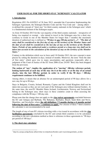
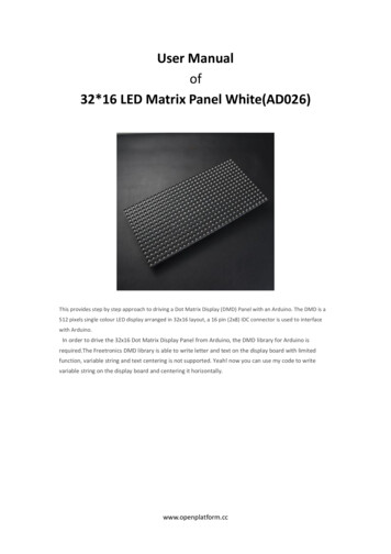
Download the Freetronics DMD library, it should be DMD-master.ZIP Extract it to the Arduino libraries folder, eg. \My Documents\Arduino\libraries\ Rename the folder from DMD-master to DMDUpload sketchOnce libraries installation completed, upload the DMD demo sketch to the DIY Arduino Open Arduino IDE Select File Examples DMD dmd demoExampleThis example write variable text on the display board and centering the text horizontally.Wire connection to Arduino UNO board as below:OE GND D9GNDA D6B D7C No connectionCLK D13SCLK D8R GD D11No connectionNo connectionwww.openplatform.cc
******Code begin******#include "SPI.h"#include "DMD.h"#include "TimerOne.h"#include "Arial black ---------------------------Only 7 of the 16 pins on the DMD are actually used:GND - Hopefully obviousnOE - Enable / Disable ALL the LEDs on the DMDA - A&B pins select which 1/4 of the DMD is selectedB - A&B pins select which 1/4 of the DMD is selectedCLK - Used to clock each pixel into the DMD shift registersSCLK - Latches the current content of the DMD shift registersR - The raw pixel data stream (NB: The 'R' stands for RED. You might notice an unused 'G' pin which is forGreen on a HUB12 connector)-------nOE(D9) 12 A(D6)Gnd 34 B(D7)Gnd 56 CGnd 68 CLK(D13)www.openplatform.cc
Gnd 710 SCLK(D8)Gnd 1112 R(D11)Gnd 1314 GGnd 1516 ------------------------------*///Fire up the DMD library as dmd#define DISPLAYS ACROSS 1#define DISPLAYS DOWN 1DMD dmd(DISPLAYS ACROSS, DISPLAYS ----------------------------Interrupt handler for Timer1 (TimerOne) driven DMD refresh scanning, this getscalled at the period set in -----------------------------------------*/void ScanDMD(){dmd.scanDisplayBySPI();}const byte PanelWidth 32;const byte MaxStringLength 5;char CharBuf[MaxStringLength 1];void setup() {//initialize TimerOne's interrupt/CPU usage used to scan and refresh the displayTimer1.initialize( 5000 );//period in microseconds to call ScanDMD. Anything longer than 5000(5ms) and you can see flicker.Timer1.attachInterrupt( ScanDMD );//attach the Timer1 interrupt to ScanDMD which goes todmd.scanDisplayBySPI()dmd.selectFont(Arial Black 16);}void loop() {String myString;myString "0"; center theDisplay(myString); delay(1000);myString "12"; center theDisplay(myString); delay(1000);myString "345"; center theDisplay(myString); delay(1000);myString "678."; center theDisplay(myString); delay(1000);}void center theDisplay(String input Str) {byte charCount, total charWidth, x position;input Str.toCharArray(CharBuf, MaxStringLength 1); //string to char arraywww.openplatform.cc
charCount input Str.length();if (charCount 0) exit;total charWidth 0;for (byte thisChar 0; thisChar charCount; thisChar ) {total charWidth total charWidth dmd.charWidth(CharBuf[thisChar]) 1; //add 1 pixel for space}total charWidth total charWidth -1; //no space for last letterx position (PanelWidth - total charWidth) /2; //position(x) of first letterdmd.clearScreen(true);for (byte thisChar 0; thisChar charCount; thisChar ) {//dmd.drawChar(x, y,‘@', GRAPHICS NORMAL)dmd.drawChar( x position, 1, CharBuf[thisChar], GRAPHICS NORMAL );x position x position dmd.charWidth(CharBuf[thisChar]) 1; //position for next letter}******Code End******Reference ringwww.openplatform.cc
32*16 LED Matrix Panel White(AD026) This provides step by step approach to driving a Dot Matrix Display (DMD) Panel with an Arduino. The DMD is a 512 pixels single colour LED display arranged in 32x16 layout, a 16 pin (2x8) IDC connector is used to interface with Arduino. In order to drive the 32x16 Dot Matrix Display Panel from Arduino, the DMD library for Arduino is required.The Freetronics .