Transcription
Images Scientific Instruments Inc.109 Woods of Arden RoadStaten Island NY 10312718.966.3694 Tel718.966.3695 Faxwww.imagesco.com3D LED Cube MatrixLED Cube Manual V1.1Page 1
This Manual shows step by step instructions for building Images 3D LED Cube. The LED matrixwe decided to use is a 4 x 4 x 4 monochromatic LED Matrix. This is a total of 64 LEDs. Thereason we chose this size, is that it provides the best of overall cube size, construction time &easier programming.The advantage to using mono-chromatic LEDs allows us to use bright LEDs. Bright LEDs inour LED cube are viewable in a well lighted room. Mono-chromatic LEDs from well knownmanufacturer are cheap and affordable, usage of mono-chromatic LEDs allows easierconstruction and programming of Cube. While the obvious disadvantage of not using RGBLEDs is that the Cube is only limited to one color. The current crop of RGB LED's don't havethe light intensity punch and when used in a 3D LED cube must be viewed in a dark room. If youlook at an RGB 3D cube in a well lighted room chances are you can't even tell that it's on. Inaddition affordable RGB LEDs are four times costlier than the mono-chromatic ones, the usageof RGB LEDs would increase the difficulty level of construction and programming.With monochromatic LEDs you have the choice of four mono-chromatic colors blue, red, greenand yellow.The kit is supplied with a preprogrammed microcontroller, that includes 29 pre-programmedpatterns that automatically play. Playtime for the 29 patterns is approximately 6-1/2 minutes.However instructions to program the 3D Matrix yourself are provided towards the end of thismanual.LED Cube Construction: Step by Step GuideTo build an accurate 3D LED Cube Matrix with evenly spaced and aligned LEDs we recommendeither building or renting a jig, see figure 1. The instructions for using a jig will be provided inthis article. If you do not wish to use a jig, you may fabricate the LED Matrix in any manner youfind convenient.The jig contains the following parts: wood base, (4) 1/4-20 bolts, 4 inches in length, (16) 1/4-20nuts, (12) LED Holders (2-styles), and (12) spacers, see figure 2.LED Cube Manual V1.1Page 2
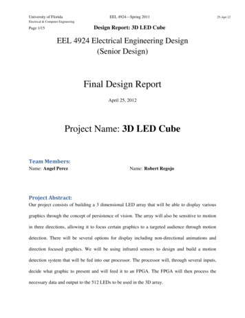
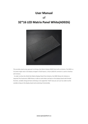
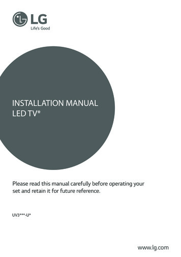
The lead photography shows the optional transparent case enclosing the LED Matrix. Unless youhave purchased the transparent case, it is not included in your kit. Visit our websitehttp://www.imagesco.com/led/cube.html for the latest information.Getting Started: Components & ToolsWe will need following tools for building LED Cube using Jig.1. Soldering Iron and Solder.2. Nose Pliers3. Diagonal (Lead) Cutters.4. 20 gauge solid wire, 1 meter in length.5. 1 qty - 2AAA Battery Holder.6. 2 qty AAA Batteries.7. 1k 1/4 Watt Resistor.Physical LayoutThe LED Cube has 64 LEDs in a 4 x 4 x 4 LED matrix, see figure 3. Four LEDs each acrosslength, width and height. Each of the 4 layers contains 16 LEDs. Physical Dimension of Cube isapproximately 2.5" x 2.5" x 2.5", consecutive LEDs are separated by 3/4".LED Cube Manual V1.1Page 3
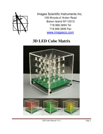
Figure 3LEDsLEDs used are 5mm (T1-3/4), round of any color, see figure 4. Rectangular/Oval Shaped LEDscan be used but may be a problem to hold in jig during construction. Diffused LENs mean awider viewing angle, better for side viewing. LED Leads should be 1” long, leads themselvesare used to connect consecutive LEDs which are 0.75 " apart.Figure 4LED Cube Manual V1.1Page 4
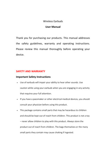
Electrical ConnectionThe schematic for the 3D LED cube is shown in figure 5. The 3D LED Cube is a 16 x 4multiplexed display, with 16 common Cathode connections and 4 common Anode connections.Each LED layer has 16 LEDs, with one common Anode. Total of 4 layers means 4 commonAnode connections. Each of 4 LEDs in a Physical Vertical Line of Cube (not schematics) has acommon Cathode connection. 16 vertical lines means 16 common cathode connections seefigure 5.Figure 5Check LEDsWhile the failure rate of new LED's is extremely low, I recommend checking your LEDs beforesoldering them in 3D Matrix structure. It is very difficult to replace a faulty LED once thematrix is constructed. A simple LED Tester can be made, see figures 6 and figures 7. Take aLED Cube Manual V1.1Page 5
two battery (AA/AAA) battery holder, solder a 1 K resistor in series with the black lead to limitcurrent to the LEDs. This is shown as –ve terminal and red wire probe is the ve terminal.Connect ve to LED’s Anode (longer lead) and –ve to LED’s Cathode, to test LEDs.Figure 6Figure 7LED Cube Manual V1.1Page 6
Cube JigSee the layout of the jig below in figure 8. Jig is made of 6” x 6” , 3/8”-1/2” thick wood. Thereis a separate construction manual for jig available, if you wish to build jig by yourself.Figure 8The sixteen red colored circles are holes with 7/32” diameter (drilled using #7 drill bit). LEDswill be inserted upside down into these holes.LED Cube Manual V1.1Page 7
The four black circles are holes with .047/3/64” diameter(drilled using #56 drill bit). Theseholes are used to hold thick tinned wires (about 0.8 mm wire without sleeve) in place.The sixteen 7/32” holes and four 3/64” holes will be used to make individual layers, while thesixteen 7/32” holes will also aid in constructing cube by joining individual layers.The four blue circles are holes with 0.25" in diameter(drilled using 1/4” drill bit). These holeshold 1/4 – 20 bolts at required positions. Diameter Numbers for holes in jig should be readable toyou if jig is oriented in correct way. Nuts come in standard heights. Depending on the localavailability you can get nuts of any height. The jig comes with spacers and nuts and when usedachieve a height of 0.75" between layers.If you do not rent the jig your goal is to stack up 3 to 4 nuts to achieve height of 2 cm (0.75”).The four 1/4" holes hold bolts, see figure 9, to which the LED holders attach to hold the layersone above the other at accurate positions. This is not as complicated as it sounds, the pictureswill explain. Bolts are a minimum of 4 in long.Figure 10 is the picture of jig base. Also note that this is the correct orientation of jig whileconstruction.LED Cube Manual V1.1Page 8
Figure 10LED Layer holders & Tube SpacersThese holders are included with the jig and are used to hold layers at their required positionabove one another. We need total of 12 holders, divided into two groups of 6. Both groups haveminor differences. See the figure 11 for strip designs.Figure 11LED Cube Manual V1.1Page 9
To make these strips use the above layout. Glue layout on 16 gauge sheet metal. Cut the sheetmetal along the borderlines with tin snips. Then use a hole-punch to mark the centers where thecross lines intersect and drill holes with required drill bits. The hole in the LED Holders are17/64” as opposed to 1/4” in the Jig base. This slight increase in this hole allows for adjustmentsin jig when positioning the LED layers. I THE holders provided with the jig are made from 1/8"acrylic.Tube Spacers are used to maintain required height of 3/4" between two layers. These spacers aremade from 3/8” OD hollow aluminum tubes, having height around 0.5”.Jig Construction manual shows how to make jig base, LED holders & tube spacers.Figure 12 shows the 12 holders and 12 spacers.Figure 12Tin Copper WiresWe will need 2 pieces of 20 AWG tin wire, 3.25" in length per layer, total of 8 wires for theentire LED cube construction, see figure 13. If you are using wire from a reel, cut to length andLED Cube Manual V1.1Page 10
it should be straightened for proper and easy soldering. Try straightening the wires as much aspossible by hand. Then put the wires on firm surface (eg. Desk), and use the Jig base to roll overthe wires, with some pressure. This will straighten them out perfectly.Figure 13Tin Wire FormingOrient the jig in correct direction as per Figure 10 . Each of the 8 tin wire pieces needs to beformed into “C” shape for accurate and easy soldering. There are 4 small 3/64" Holes drilledinto jig, with correct orientation, a pair of them will be in a vertical lines perpendicular to you.Take a tin wire piece and make a 90 degree bend at 0.25" from one end. Insert 0.25" bentportion in one of the 3/64" holes and align wire with the other 3/64" hole along the vertical line.Hold the wire over the second hole with Nose Pliers, lift bent end from previous hole and make a90 degree bend at the position where the Nose Pliers holds the wire. This will give the C shapeto the Wire. Repeat the process for rest of the 8 wire pieces. Figure 14 shows the jig with two tinwires preset in the 3/64" holes, ready to start accepting LEDs.LED Cube Manual V1.1Page 11
Figure 14LED Leads FormingLED Cube Manual V1.1Page 12
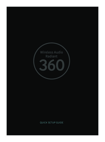
Figure 15We are going to use LED leads to help solder LED’s in each layer. The most important step isbending the LED leads properly. Figure 15 is a graphic that provides an overview of the foursteps. The longer lead of the LED is the anode and is colored red. The shorter lead is thecathode, shown as black. All 64 LEDs leads will be formed in the following manner. Let'sproceed in a step by step manner.Step 1, hold the LED in your hand so thatperpendicular to you see figure 16.anode and cathode leads are along a lineLED Cube Manual V1.1Page 13
Figure 16The anode should be closer to you while the Cathode should face outwards. From the base ofcathode lead, bend the lead outwards by 90 degrees, along the line perpendicular to you, seefigure 17.Figure 17Next bend the anode lead from its base by 90 degrees to the left, along a line parallel to you, seefigure 18. Holding the leads from the middle portion is an efficient way of bending them. Nowthe anode and cathode leads are perpendicular to each other.LED Cube Manual V1.1Page 14
Figure 18Now hold the bent Cathode Lead 0.25" from its base using needle nose pliers and make a 90degree downward bend where the Nose Pliers are holding the Cathode Lead, see figure 19.Figure 19After bending the 64 LEDs in the above manner, we are ready to begin building the LED cubelayers.Making Individual LayersLED Cube Manual V1.1Page 15
Orient Jig, so that the 3/64" holes are on the top and bottom of the jig facing you, as shown infigure 10. Each layer is made of 16 LEDs.Put two C shaped tin wires in place along the four 3/64" holes, see figure 20. The small bentsections of each tin wire should go inside 3/64" holes,Figure 20Insert bent LEDs upside down into top right corner 7/32" hole, see figure 21. LED should beoriented such that bent Anode Lead (which rests parallel with Jig surface) is along the horizontalline parallel to you.LED Cube Manual V1.1Page 16
Figure 21Insert second LED into the hole to the left of the previous one using the same orientation.Repeat this process for rest of the LEDs. When all 16 LEDs are inserted (for each row of 4LEDs), their bent Anode leads should overlap some and form a horizontal line.The LEDs are soldered together at the overlaps as shown in Figure 22.LED Cube Manual V1.1Page 17
Figure 22Solder the overlapping Anode portions, a total of 12 solder joints. Solder LED Leads quicklysince longer contact period between the Solder Iron and LED Leads could damage the LED.Also remember to solder the 8 solder joints where the two tin wires overlap the four HorizontalAnode Lead Lines. When you are finished the LED layer may be removed from the Jig, bygently pulling the upwardly bent Cathode leads, as shown in figure 23.LED Cube Manual V1.1Page 18
Figure 23Cut off the extra portion of tin wire that went into the 3/64" holes, see figure 24.LED Cube Manual V1.1Page 19
Figure 24At this point you can use the LED tester to test LEDs in the completed layer. To do so, touch thepositive terminal to the uncut Common Anode Lead on the right and negative terminal toupwardly bent cathodes one by one.Continue building three more layers and testing each of them in the same manner as described.Figure 25 shows a completed LED layer removed from jig.LED Cube Manual V1.1Page 20
Figure 25Notice in figure 25, on the right hand side of the layer we have four extended anode leads. Eachlayer only needs one extended anode lead, rest of them should be removed. Each layer differsfrom another in terms of position of uncut Common Anode Layer Lead and that is how we willbe referring to the different layers from now onwards. Arrows in figure 26 indicate uncutcommon anode layer leads.LED Cube Manual V1.1Page 21
Figure 26Soldering Layers to form CubeInsert 4 bolts into the 4 corner 1/4 holes. Secure each bolt to jig using nut.Place LED Layer 0 in the jig holes. Pay attention to which side is the side with the extendedanode lead.Go to each bolt. On top of the existing nut place a spacer, then on top of the spacer, place a LEDlayer holder, then on top of the LED holders another 1/4-20 nut to secure everything down.Secure Layer 1 into the LED holders, keep the extended anode leads on the same side as ofLayer 0, see figure 27.LED Cube Manual V1.1Page 22
Figure 27The bent cathode leads of the LEDs layers should overlap. If the cathode leads don’t touch eachother, use narrow tweezers to bend cathode leads so they are in contact with previous layersLED. Solder the overlapping cathode leads, a total of 16 cathode solder joints, per layer asshown in figure 28. The red circles highlight the vertical cathode solder joints for layers 0 and l.LED Cube Manual V1.1Page 23
Figure 28Place Layer 2 with 4 Corner LEDs into 4 corner holes LED holders, as shown in figure 29.Solder vertical cathode leads as before.LED Cube Manual V1.1Page 24
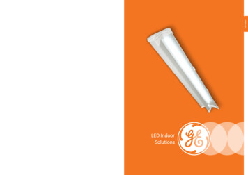
Figure 29Place Layer 3 with 4 Corner LEDs into 4 corner holes LED holders, as shown in figure 30.Solder vertical cathode leads as before. Notice how the extended anode leads are position on oneside of the 3D LED matrix. The 4 extended common anode layer leads, one for each layer, endup in staircase manner (arrows). This is important when we solder the matrix to the pc board.LED Cube Manual V1.1Page 25
Figure 30You can use th
LED Cube Manual V1.1 Page 1 Images Scientific Instruments Inc. 109 Woods of Arden Road Staten Island NY 10312 718.966.3694 Tel 718.966.3695 Fax www.imagesco.com 3D LED Cube Matrix . LED Cube Manual V1.1 Page 2 This Manual shows step by step instructions for building Images 3D LED Cube. The LED matrix we decided to use is a 4 x 4 x 4 monochromatic LED Matrix. This is a total of