Transcription
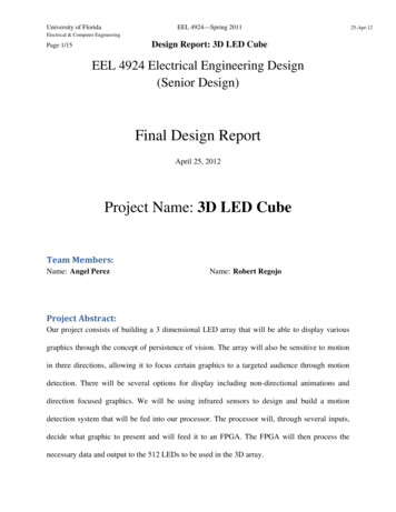
University of FloridaEEL 4924—Spring 2011Electrical & Computer EngineeringDesign Report: 3D LED CubePage 1/15EEL 4924 Electrical Engineering Design(Senior Design)Final Design ReportApril 25, 2012Project Name: 3D LED CubeTeam Members:Name: Angel PerezName: Robert RegojoProject Abstract:Our project consists of building a 3 dimensional LED array that will be able to display variousgraphics through the concept of persistence of vision. The array will also be sensitive to motionin three directions, allowing it to focus certain graphics to a targeted audience through motiondetection. There will be several options for display including non-directional animations anddirection focused graphics. We will be using infrared sensors to design and build a motiondetection system that will be fed into our processor. The processor will, through several inputs,decide what graphic to present and will feed it to an FPGA. The FPGA will then process thenecessary data and output to the 512 LEDs to be used in the 3D array.25-Apr-12
University of FloridaEEL 4924—Spring 2011Electrical & Computer EngineeringPage 2/15Design Report: 3D LED CubeTable of ContentsTeam Members: . 1Project Abstract:. 1Project Features/Objectives: . 3Concept/Technology Selection: . 4Flowcharts & Diagrams: . 6Separation of Work: . 13Gantt chart:. 14Table of FiguresFigure 1: Hardware Flowchart: . 6Fiugre 2: Softwre Flowchart . 7Fiugre 3: Finsihed LED Cube Array . 8Figure 4: MSP430 and External Devices Schematic . 9Fiugre 5: FPGA Schematic . 10Fiugre 6: FPGA Communication Schematic . 11Fiugre 7: Proximity Sensor Schematic . 1225-Apr-12
University of FloridaEEL 4924—Spring 2011Electrical & Computer EngineeringPage 3/15Design Report: 3D LED CubeProject Features/Objectives:The goal of this design is to be able to output and modify the LED array fast enough to see apersistent image: The first issue that must be dealt with is the physical construction of the array. The arraywill be 8x8x8 LEDs, accounting for a total of 512 devices. Due to lack of accessibility wewill have to make certain that each LED is functional and stays so throughout theconstruction. A sturdy base and casing will also have to be provided for the array, as the constructiondoesn’t allow for a large amount of structural integrity. A wooden base and a Plexiglascase is proposed to deal with this issue and to protect the LED array from general jostlingand movement. Due to the very large number of LEDs that need to be used at once, currentconsiderations will have to be taken into account, verifying that we have enough power tosupply a good level of luminescence so that we may not only turn on all LEDs but alsomodify them through pulse width modulation. The microprocessor will be in charge of user inputs, motion detection and general codedevelopment for the graphics. It will process all inputs and verify what set of parametersneed to be outputted to the FPGA. It will also control the pulse width modulation thatwill be used to modify the dimness of the LEDs The FPGA will process the various inputted signals and implement the digital hardwarenecessary to output the 64 signals required to functionally modify the LED array. Here25-Apr-12
University of FloridaEEL 4924—Spring 2011Electrical & Computer EngineeringPage 4/15Design Report: 3D LED Cubewe are looking to make the code as fast as possible, so as not to create a bottle neck inour refresh rate. Since each LED needs to be controlled individually, memory issues will have to beconsidered when adding more graphic options. Otherwise, we will have to find ways tostreamline our code to allow for more variety without a significant increase in thememory needed. The motion detection system will be built from scratch using infrared detection. It will beable to detect motion and focus an image to wherever the motion is detected.Concept/Technology Selection:We have chosen the implementation of this project based on our teams experience andthe simplest methods by which we see to complete our goals. When constructing the actual LEDarray we have chosen to construct the array in layers, verifying that all LEDs function after everystep. Due to close proximity soldering there is a high chance that some of them may burn out andwe would like to catch this early on. Once we have all layers completed we will stack them andsolder the layers on by one till they are fully assembled. We shall also place several strongstrands of wire to support the structure and increase its integrity.We have chosen to do the main processing in C through our MSP430. Since both teammembers have significant experience in coding this device and language it will help developmore intelligent and succinct code. The digital hardware that will be the basis for the LED driverwill come from an FPGA. This will allow us the benefit of speed to update outputs as fast as25-Apr-12
University of FloridaEEL 4924—Spring 2011Electrical & Computer EngineeringPage 5/15Design Report: 3D LED Cubeneeded as well as reducing our design footprint. Though the PCB design may be more difficultthe result would be much more beneficial than using several ICs, especially due to the largenumber of outputs we require.There are two ways in which we can fashion the code to control the LEDs. The firstwould be to preprogram individual bits to be retrieved and outputted sequentially. This is thebrute force method but it may prove easier than the others. The main issue however is memoryallocation and size, for multiple graphics or the addition of new ones we will probably need toadd external memory to process it. The second method which is the one we will attempt is tomake code as intelligently as possible so that the designs can be created and output directly fromthe microprocessor, without other hardware required. This method may be slower but it would bemore eloquent and require a physically smaller design. The best solution may be a combinationof the two systems to achieve a maximum number of graphics possible.Finally, our implementation of our motion sensor shall be designed from scratch. Whilethere are several easy to purchase motion detection devices in the market we will have moreflexibility with the design, placement and response by creating it ourselves. We have chosen tohave a minimum of three motion detectors to account for three intended viewing angles of thecube, front, left and right. This will allow us full awareness of detection surrounding the cubeand allow us the possibility to change graphics as needed.25-Apr-12
University of FloridaEEL 4924—Spring 201125-Apr-12Electrical & Computer EngineeringDesign Report: 3D LED CubePage 6/15Flowcharts & Diagrams:USER INPUTPROCESSORINFAREDTRANSMITTERFPGA/LED DRIVERINFARED RECIEVERLED ARRAYFigure 1: Hardware FlowchartLCD
University of FloridaEEL 4924—Spring 2011Electrical & Computer EngineeringPage 7/15Design Report: 3D LED CubeFigure 2: Software Flowchart25-Apr-12
University of FloridaEEL 4924—Spring 2011Electrical & Computer EngineeringPage 8/15Design Report: 3D LED CubeFigure 3: Finished LED Cube Array25-Apr-12
University of FloridaEEL 4924—Spring 2011Electrical & Computer EngineeringPage 9/15Design Report: 3D LED CubeSchematicsFigure 4: MSP430 and External Devices Schematic25-Apr-12
University of FloridaEEL 4924—Spring 2011Electrical & Computer EngineeringPage 10/15Design Report: 3D LED CubeFigure 5: FPGA Schematic25-Apr-12
University of FloridaEEL 4924—Spring 2011Electrical & Computer EngineeringPage 11/15Design Report: 3D LED CubeFigure 6: FPGA Communication Schematic25-Apr-12
University of FloridaEEL 4924—Spring 2011Electrical & Computer EngineeringPage 12/15Design Report: 3D LED CubeFigure 7: Proximity Sensor Schematic25-Apr-12
University of FloridaEEL 4924—Spring 2011Electrical & Computer EngineeringPage 13/15Design Report: 3D LED CubeSeparation of Work:The work was separated in such a way that both of us would be working on differentparts of the project at the same time until spring break was over. This of course was done afterthe led array was built. We decided to split the workload in the following ways. Robert wouldfirst handle designing the proximity sensors. This will include designing, simulating, andbuilding the sensors using IR detection. While Rob works on this, Angel will be working on thedesign of the led controller. This will consist of designing the PCB board including the FPGA.The controller will link the outputs of the registers to the LED’s and receive the inputs from themain board, which will hold the micro controller. Once this is done the focus will then be gearedinto coding the FPGA which will be done by Robert and begin the coding process of the mainboard which will be done by Angel.The FPGA coding will consist of implanting both shift registers and multiplexers. Theshift registers will be the output to the each led pin while the multiplexer will control which layeris activated at a time. The coding of the main board will consist of implementing the proximitysensors with the user interface buttons, LCD coding and setting up the functions in order to addthe graphics later to the main code. Once this task is done the focus will then be turned intodesigning the main board which will hold the processor, sensors connectors, transistors, userbutton connector, power supply, and LCD connector. This task will be done mostly by Robert.While this is done Angel will be working on programming the first set of graphics for the Array.Once the main board is designed both of us will focus on implementing the hardware and makesure that the first graphic can be demonstrated. After this is done the graphic programming willthen be split between the both of us.25-Apr-12
University of FloridaEEL 4924—Spring 201125-Apr-12Electrical & Computer EngineeringPage 14/15Design Report: 3D LED CubeThe work load from there on out will be done mutually. This will include building thehousing for the array, the housing for the electronics, and also will include testing and debuggingthe whole project. The schedule of how the work is separated can be seen on the Gantt chartbelow.Gantt chart:Start DateSubtask 1Subtask 2Subtask 3Problem determined7-Jan-12333Research project9-Jan-121400Design LED Array2-Feb-122030Design Proximity Sensors17-Feb-122030Design LED Controller17-Feb-1220303-Mar-121200Mainboard Design26-Mar-12500FPGA Coding12-Mar-12770Graphic Design Coding29-Mar-122800Processing Programing12-Mar-127729-Apr-12550Case Design13-Apr-121400Final Testing19-Apr-121400Presentation25-Apr-12550Spring BreakHardware Implementation
University of FloridaEEL 4924—Spring 2011Electrical & Computer EngineeringPage 15/15Design Report: 3D LED Cube25-Apr-12
The goal of this design is to be able to output and modify the LED array fast enough to see a persistent image: The first issue that must be dealt with is the physical construction of the array. The array will be 8x8x8 LEDs, accounting for a total of 512 devices. Due to lack of accessibility we will have to make certain that each LED is functional and stays so throughout the construction. A .
