Transcription
V-Cube Slim Air HandlerInstallation, Operation and Maintenance ManualSizes: 180 to 840Model: E Series 2011 Mammoth, Inc.P/N 71144920
Table of ContentsModel Nomenclature ··············3Transportation and Storage ····3Installation ·····4Unit Location ·4Disassembly and Assembly Instructions ·········5Ductwork and Attenuation ······7Ventilation Air 7Supply Piping 8Condensate Piping ·················8Cleaning and Flushing ············9Start-up ·······10Operating Limits ···················10Mammoth DDC Controls ······11General Maintenance �··············14Check out sheet OM-2EB (October 2011)2
Model NomenclatureFV-H-EModel Size*Unit TypeTemperature RangeDesign SeriesF 208-230/60/3180 180,000V VerticalH Standard RangeG 460/60/3280 280,000J 380-415/50/3350 350,000K 575/60/3530 530,000Voltage-185-700 700,000840 840,000*Packaged configurations available for all model sizes. See MAMM-VCS-IOM-1EB for units that include packaged refrigeration components.Transportation and StorageUpon receipt of the equipment, check for visible damage. Make a notation on the shipper’s delivery ticketbefore signing. If there is any evidence of rough handling, immediately check for concealed damage. If anydamage is found, notify the carrier within 48 hours toestablish your claim and request their inspection and areport. Then contact the Mammoth Service departmentat (952) 358-6618 or info@mammoth-inc.comfor a warranty claim number.MAMM-VCS-IOM-2EB (October 2011)Do not stand or transport the unit on end.Temporary storage at the job site must be indoors,completely sheltered from rain, snow, etc. High or lowtemperatures naturally associated with weather patterns will not harm units. Excessively high temperatures, 140 F (60 C) and higher, may deteriorate certainplastic materials and cause permanent damage.3
InstallationGeneralIMPORTANT:Mammoth V-Cube Slim units should be installed onlyby qualified personnel, experienced in the installationof this equipment and related systems. Read theseinstructions carefully before unpacking, installing andoperating this unit1. To prevent damage, this equipment should not beoperated for supplementary heating and coolingduring the construction period.2. Inspect the unit for any specific tagging numbersindicated by the factory per a request from the installing contractor.3. Check the unit nameplate for the size and voltagerating and confirm against the plans that the unit isbeing installed in the correct location.4. Verify the installation location with the piping, sheetmetal and electrical contractors prior to installation5. Verify all clearances are available for the unit priorto installation.6. Note the location and routing of water piping, condensate drain piping, and electrical wiring. The locations of these items are clearly marked on submittal drawings.7. Mammoth recommends the unit be covered duringconstruction to protect components from dust andother harmful material. This is critical while spraying fireproofing material on bar joists, sandblasting,spray painting and plastering.NOTE:Check the unit name plate for correct voltage with theplans before installing the equipment. Make sure allelectrical ground connections are made in accordancewith local code.Unit LocationLocate the unit in an area that allows for easy removalof the filter and access panels. Leave enough space forservice personnel to perform maintenance or repair.Provide sufficient room to make water, electrical andMAMM-VCS-IOM-2EB (October 2011)duct connections. Refer to submittal drawings forproper service clearance dimensions. Install unit incompliance with all state and local codes.4
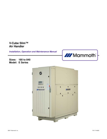
Disassembly and Assembly Instructions ForV-Cube Slim UnitsV-Cube Slim units are designed to allow forinstallation in new facilities and as a retrofit for older,obsolete equipment.NOTE:Please read all disassembly instructions completelybefore starting any disassemblyDANGER!A mechanical lift is required to move or lift all sectionsof a V-Cube Slim unit. Do not attempt to move or liftsections without a mechanical lift. Failure to do so canresult in equipment damage, severe personal injury ordeath.DANGER!Lifting the entire unit (blower section, coil section, etc.)using lifting lugs, eye bolts or straps attached to the topof the unit can result in serious damage to the unit,personal injury or death.Lifting the entire unit should only be done using a forklift or a strapping spreader bar mechanism attached tothe base of the unit.DANGER!It is mandatory that all utilities (water, electric, andcommunication cables to the Building ManagementSystem) be removed prior to unit disassembly. Followapproved lockout/tagout procedures before any disassembly of the unit. Failure to do so can result in electric shock, equipment damage, severe personal injury,or death.The standard unit consists of three sections—the electrical control panel, the coil section and the blower section. Units with an optional waterside economizer orhot/chilled water coil will have an additional section forthat coil.The disassembly of sections requires removal of the3/8” bolts holding them together while supporting eachsection as it is being removed with rigging equipment.Step 1 – Remove the electrical panelUnplug the wire harness that connects the EPiC keypad and reset buttons/selector switches from the paneldoor to the main electrical panel. Remove the paneldoor by lifting it from its hinges and carefully set aside,away from the unit to help prevent damage during theremaining disassembly process.Unplug all control wiring harnesses that run from themain electrical panel to the main cabinet section.These plugs are labeled for correct re-installation. Finally, remove all high voltage wiring to the fan motors.Once all electrical connections to other sections in theunit have been removed, make sure that the electricalpanel is supported from above or below to prevent itfrom falling once the bolts that connect it to the maincabinet sections are loosened and removed.Loosen and remove the section bolts that fasten themain electrical panel to the main cabinet sections(Figure 1). Set the main electrical panel aside, awayfrom the unit to help prevent damage during the remaining disassembly process.Figure 1—Electrical Control Panel BoltsNOTE:All blower wiring is correctly phased at the factory andmust be re-wired correctly upon re-assembly for correct compressor and blower operation. Mark all wiresand pull through knockouts using care not to scrapethe insulation of the wiring when separating sections. Ifthe wire insulation or wire jacket is torn during the disassembly/re-assembly procedure, replace the wire. Donot use wire that is missing insulation. Control andsensor wiring use Molex plugs for proper polarity.Remove the bolts usedto mount the electricalcabinet to the main unitsections. There are 6bolts on the side of theunit.Your new V-Cube Slim will come fully assembled. Inthe event building layout prohibits the unit to be movedto its final location as a whole assembly, it will be necessary to disassemble the unit into its basic sectionsand reassemble it at the final location.MAMM-VCS-IOM-2EB (October 2011)5
Step 2 – Remove optional heating coil sectionThis step only applies to units with an optional heatingcoil.Figure 3—Removal of Blower Section BoltsRemove the bolts that connect the welded base of theheating coil section to the welded base of the maincabinet section.Remove the access panels on each side of the optionalheating coil cabinet shown in Figure 2. Inside the optional heating coil section, disconnect wiring to anyvalves and/or air sensors that run to the other sectionsin the unit.Once all electrical connections to the other sections inthe unit have been removed, loosen and remove thesection bolts that fasten the optional heating coil cabinet to the main cabinet. Set the optional heating coilsection aside, away from the unit to help prevent damage during the remaining disassembly process.Figure 2—Optional Heating Coil Section RemovalRemove Section BoltsRemove the water pipe extensions at the Victaulic connection point inside the unit. Attach lifting straps to themotor mount plate as shown in Figure 4 and attach to aspreader bar or forklift fork. Also attach ropes or chainsto the eye bolt on one of the motors and attach to eachend of the spreader bar or fork to level the load of theblower section.Figure 4—Lifting the Blower SectionCAUTION!Remove Section BoltsStep 3 – Removing the blower cabinetRemove the main cabinet access panels (Figure 3).Feed any wiring for the blower motors and/or air sensors passing through the coil section through the chaseway into the blower cabinet.Remove the section bolts that attach the blower cabinetto the coil section (Figure 3).MAMM-VCS-IOM-2EB (October 2011)Lifting straps are to be used in lifting the blower sectiononly. Do not attach eye bolts to the motor mount plateand attempt to lift the blower section. Failure to do socan result in equipment damage and personal injury.Use these instructions in the reverse order for assembly. Replace any torn or damaged gasket with newmaterial. Apply a bead of silicon caulking between sections while reassembling to minimize air leaks.For further information or assistance with these procedures, contact the Mammoth Service department.6
Ductwork and AttenuationDischarge ductwork is normally used with the V-CubeSlim . Return air ductwork may also be required.All ductwork should conform to industry standardsof good practice as described in the ASHRAE SystemsGuide.The discharge duct system will normally consist ofa flexible connector at the unit connection, a transitionpiece to the full duct size, a short run of duct,and elbow with vanes, and a trunk duct teeing intoa branch duct with discharge diffuses. The transitionpiece must not have angles totaling more than30 or severe reduction in airflow performance can result.Do not connect the full duct size to the unit. Use a transition piece sized according to the discharge collar onthe unit to get to the full duct size. With metal duct material, the sides of only the elbow and entire branchduct should be internally lined with acoustic fibrous insulation for sound attenuation. Glass fiber duct boardmaterial is more absorbing and may permit omission ofthe canvas connector.The ductwork should be laid out so that there is noline of sight between the unit discharge andthe distribution diffusers.Return air ductwork (if used) should be connected tothe unit using the filter section flange.Ventilation AirOutside air may be required for ventilation. The temperature of the ventilation air must be controlled so thatthe mixture of outside air and return air entering theunit is within application limits. It is typical to close offthe ventilation air system during unoccupied periods(i.e. night setback).MAMM-VCS-IOM-2EB (October 2011)The ventilation air system is typically a separate building subsystem with distribution ductwork. Simple introduction of the outside air into each return air plenumchamber reasonably close to the unit air inlet isrecommended. Do not duct outside air directly to theunit inlet. Provide sufficient distance for the thoroughmixing of outside and return air.7
Supply Piping1. All units should be connected to supply and returnpiping in a two-pipe reverse return configuration. Areverse return system is inherently self-balancingand requires only trim balancing where multiplequantities of heat pumps with different flow andpressure drop characteristics exist in the sameloop. Check for proper water balance by measuringdifferential temperature reading across the waterconnections.2. The piping may be steel, copper or PVC. Avoiddissimilar metal fittings as they may corrode. If theuse of dissimilar metals cannot be avoided, usedielectric isolation at that connection point3. Supply and return run outs usually join the unit viashort lengths of high pressure flexible hose whichare sound attenuators for both unit operating noiseand hydraulic pumping noise. One end of the hoseshould have a swivel fitting to facilitate removal forservice. Hard piping water connections is not recommended due to the possibility of vibration thatcan damage connections or pipe joints or noiseattenuation. Any hard piped connections must contain a union to facilitate removal of the piping orunit.4. Some flexible hose threaded fittings are suppliedwith sealant compound. If not, apply Teflon tape toprovide a tight seal.5. Supply and return shutoff valves are required ateach unit. The return valve is used for balancingand should have a “memory stop” so that it canalways be closed off but can only be reopened tothe proper position for the flow required.6. No unit should be connected to the supply and return piping until the water system has been cleanedand flushed completely. After the cleaning andflushing has taken place, the initial connectionshould have all valves wide open in preparation forthe water system flushing.Condensate Piping1. Condensate piping can be steel, copper, or PVC.Each unit includes a condensate connection.2. The condensate disposal piping must be trapped.The piping must be pitched away from the heatpump not less than ¼” per foot. The unit is suppliedwith a 1-1/4” male pipe fitting to accommodate thecondensate drain connection.MAMM-VCS-IOM-2EB (October 2011)3. Do not locate any point in the drain system abovethe drain connection of any unit.4. The condensate piping system must be vented atits highest point.8
Cleaning and Flushing1. Prior to first operation of the V-Cube Slim , thewater circulation system must be cleaned andflushed of all construction dirt and debris.2. If the unit is equipped with water shutoff valves,either electric or pressure operated, the supply andreturn run-outs must be connected at each unit location. This will prevent the introduction of dirt intothe unit.3. Fill the system with water with all air vents open.When the unit is filled with water, close all air ventsto remove all air.4. Start the main circulator with the pressure reducingvalve open. Check vents in sequence to bleed offany trapped air to provide circulation through allcomponents of the system.5. While circulating water, check for and repair anyleaks in the piping. Drains at the lowest point(s) inthe system should be opened for the initial flushand blow down, making sure city water fill valvesare set to make up water at the same rate. Checkthe pressure gauge at the pump suction and manually adjust the makeup to hold the same positivesteady pressure both before and after opening thedrain valves. Flush should continue for approximately two hours, or until the drain water is clearand clean.6. Shut off supplemental heater (if applicable) andcirculator pump and open all drains and vents tocompletely drain down the system. Short circuitedsupply and return run-outs should now be connected to the unit supply and return connections.MAMM-VCS-IOM-2EB (October 2011)7. Refill the system with clean water. Test the waterusing litmus paper for acidity, and treat as requiredto leave the water slightly alkaline (pH 7.5 to 8.5).The specified percentage of antifreeze may also beadded at this time. Use commercial grade antifreeze designed for HVAC systems only. Do notuse automotive grade antifreeze.8. Once the system has been filled with clean waterand antifreeze (if used), precaution should be takento protect the system from dirty water conditions.Dirty water will result in system wide degradation ofperformance and solids may clog valves, strainers,flow regulators, etc.9. Set the loop water controller heat add setpoint to70 F and the heat rejection setpoint to 85 F. Supply power to all motors and start the circulationpumps. After full flow has been established throughall components including the heat rejecter(regardless of season) and air vented and looptemperatures stabilized, each of the units will beready for check, test and start-up, and water balancing.9
Start-up1. Open all valves to the full open position and turn onpower to the V-Cube Slim .2. Set room temperature sensor for “Fan Only” operation by selecting “Off” at the system switch and“On” at the fan switch. If “Auto” fan operation is selected, the fan will cycle. Check for proper air delivery.3. Measure the temperature difference between entering and leaving water. The difference in watertemperature should be approximately 1 ½ timesgreater in the cooling mode as compared to theheating mode . Adjust the combination shutoff/balancing valve in the return line to a water flowrate which will result in the temperature difference.4. In the heating mode, with the entering water temperature in the range of 60 F to 80 F, the temperature difference between the entering water andleaving water should be between 6 F to 12 F. Inthe cooling mode, if the leaving air temperaturefalls below 35 F, adjust water flow to the unit to 3gpm/ton to avoid freeze damage to the unit.5. To verify proper drainage of condensate, slowlyadd water to the condensate pan until proper drainage is accomplished.6. If the unit fails to operate, check the following:a. Verify that the incoming power to the unitmatches the nameplate and that the main disconnect is turned on.b. Verify a call for heating or cooling is present.7.If the unit starts but after a short time trips on highor low head pressure, check the following:a. Verify that airflow is not impeded by a dirty airfilter, improper fan rotation or improper ductsizing.b. Verify that the water flow rate is within limits.Check the water flow balance and back flush ifnecessary.Additional Information For Initial Start-up OnlyOperating voltages208-230/60/3 . . . . . . . . . . . . . . . . . . . . 197 volts min.; 253 volts max.460/60/3 . . . . . . . . . . . . . . . . . . . . . . . . 414 volts min.; 506 volts max.380-415/50/3. . . . . . . . . . . . . . . . . . . . .342 volts min.; 418 volts max575/60/3. . . . . . . . . . . . . . . . . . . . . . . . .515 volts min.; 632 volts max.Note:Voltages listed are to show voltage range. However,units operating with over– or under-voltage conditionsfor extended periods of time will experience prematurecomponent failure. Three phase system
V-Cube Slim Air Handler Installation, Operation and Maintenance Manual Sizes: 180 to 840 Model: E