Transcription
CommercialDuct HeatersOur products do more in a widerange of applications. Expect More.
IntroductionIndeeco designs and manufactures commercial and industrial electric heatingand control systems that set the industry standard for excellence. Thecompany’s heating solutions reflect more than 85 years of innovation, productquality and efficient service. Indeeco’s innovation, PC HEAT , is customsoftware that enables our representatives to respond to your requests forpricing and sizing of open coil and finned tubular duct heaters within minutes.With this software, your local Indeeco representative becomes the source forcertified prints, wiring diagrams — complete submittal information.Our heaters and controls range from the simplest standard duct heater tothe most sophisticated, custom designed comprehensive system. Indeeco’sattention to detail and rigorous testing give worldwide customers premiumproducts that they receive quickly and at a fair market price.
ContentsChoosing Open Coil or Finned Tubular DesignSpecific Requirements334456677Calculating KW RequirementsStatic Pressure DropMinimum VelocityMaximum VelocityAirflow UniformityMultiple Heaters in the DuctClearanceUL and NEC RequirementsInternational RequirementsInstallation Information88Heater InstallationField WiringStandard Control Options1010101112Internal WiringControl Option G — BasicControl Option J — PneumaticControl Option K — ProportionalThermostatsConstruction – allic Thermal CutoutsLinear Thermal CutoutsAirflow SwitchFan RelayMagnetic ContactorsFusesControl TransformerDisconnect SwitchPilot LightsPilot SwitchPneumatic/Electric (PE) SwitchesElectronic ControlsSCR Power ControllersStep Controllers (Sequencers)Step Controllers (Microprocessor-based)Vernier Proportional ControlThermostats/Inputs for Electronic ControlsConstruction – Mechanical22222223Slip-in HeatersFlanged HeatersZero Clearance ConstructionPhysical StandardsStandard Duct Heaters – Open Coil24242425262626262731QUA Slip-in and QUZ Flanged HeatersKW RatingsFrame SizesSizes and Maximum KW RatingsDetail DimensionsVoltage and PhaseControl Circuit Options & Special FeaturesNumber of Heating StagesSpecial FeaturesQUA/QUZ – Sample SpecificationCustom Duct Heaters3233343535353636363737373940Special ApplicationsRound Duct ConstructionDuct Heaters for Wet, Dusty and Corrosive AreasBottom Mounted Terminal BoxInsulated Terminal BoxPressure PlatesProtective ScreensUnheated SectionsConstruction for Lined DuctsSlip-and-Drive ConstructionRemote PanelboardMinimum & Maximum Duct DimensionsOpen Coil Custom Heater – Sample SpecificationFinned Tubular Custom Heater – Sample SpecificationExplosion-proof Duct plete Product LineApplicationsUse of Electric Heaters in Hazardous AreasNational Electrical Code ClassificationClassDivisionGroupEngineering InformationAirflow RequirementsComparison ChartULTRA-SAFE Explosion-proof Duct Heaters46464748495050Standard ConstructionInstallationTemperature ControlStandard Heater ListingCustom OptionsHow to OrderSample SpecificationSeries EP2 Explosion-proof Duct Heaters515151525353Standard ConstructionControl OptionsInstallationCustom OptionsHow to OrderSample SpecificationCustom Explosion-proof Duct Heaters54555556ConstructionHow to OrderSample SpecificationTypical Wiring DiagramsLimited WarrantyMore Indeeco Productswww.indeeco.com800-243-81621
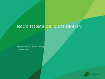
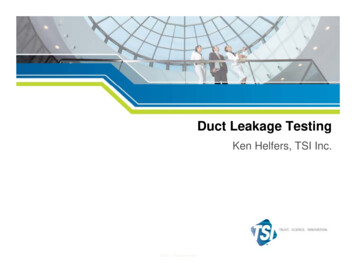
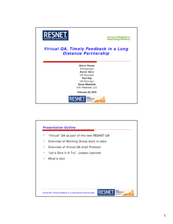
Choosing Open Coil or Finned TubularDesignIndeeco manufactures both open coil (Figure 1) and finnedtubular (Figure 2) heating elements and can supply virtually anyduct heater with either type of element. While most simple spaceheating applications use the open coil design, there are manyapplications where finned tubular construction is appropriate.The following are the significant advantages of each type ofconstruction.Open CoilLarge Electrical Clearances – Generous electrical clearancesbetween the coil and frame enable open coils to withstandsevere applications such as subway car heating, where voltagesmay exceed 750 volts.Economy – On relatively small, low KW heaters (thebulk of typical space heating applications) the open coil elementis more economical. However, in large, high KW heaters, finnedtubulars are more economical due to lower manufacturing costs.Smaller Size – It is normally possible to get more KW with opencoil construction for a given face area.Finned TubularTwo-passFigure 1.Only the highest Grade A resistance wire (80% nickel, 20%chromium) is used in all Indeeco duct heaters. This iron-free wirehas a higher maximum operating temperature, greater life, lowersag, less resistance change and higher corrosion resistance thanother commonly used resistance wires.Using calibrated tooling, the coils are mechanically crimpedinto stainless steel terminals. This connection, along with 10-32terminal threads and stainless steel connection hardware,insures cool, minimum resistance, trouble free terminations.An extended shank on the terminal places the critical resistancecoil-to-terminal connection well out into the airstream to keep itcool even in applications where up to 1” of interior insulation isused in the duct.Both terminal insulators and coil support insulators arefabricated from high-temperature ceramic. Their designand method of installation enable them to: 1) absorb bothmechanical and thermal loading without chipping or crackingand 2) easily withstand high voltage dielectric tests.Element Temperature – The open coil element releases its heatdirectly into the airstream. As a result, the open coil runs coolerthan the coil in the finned tubular element which is isolated fromthe air by insulation and a metal sheath.Low Pressure Drop – Because of the high percentage of openspace across the heater, open coils have very low pressuredrop as compared to finned tubular heaters. This can result inreduced fan motor horsepower and makes it possible to retrofitopen coil heaters into existing systems without changing the fanmotor.2U-BentStraightFigure 2.Finned tubular elements are designed and built by Indeeco tomeet the requirements of each job. Length, wattage, voltageand element style are engineered to give the most economicalpackage.All elements consist of a Grade A coil (80% nickel, 20%chromium), precisely centered in a stainless steel tube whichis filled with granular magnesium oxide. The entire assemblyis compacted to maximize both the heat transfer and dielectricproperties of the magnesium oxide. After compaction the tubemeasures 0.475” (12 mm) O.D., an unusually large diameterproviding sufficient insulation for operation up to 600 volts.A stainless steel fin is helically wound onto the tube to increaseits heat transfer surface.Indeeco has standardized on stainless steel for its finned tubularelements because of its superior resistance to moisture andcorrosion.Straight, Two-Pass and U-Bent elements are furnished withmounting flanges, making them individually removable throughthe terminal box.www.indeeco.com800-243-8162
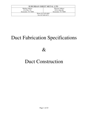
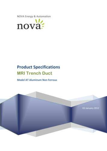
Specific RequirementsSafety – Because the heating coil is completely encased ina grounded metal sheath, shock hazard due to accidentalcontact with the coil is eliminated. Heaters installed close to aregister, grille, or access door should either use finned tubularconstruction or an open coil unit with a protective screen.Where the desired heating capacity in BTU/Hr is known, the KWis determined from the following formula:KW BTU/Hr3412Airflow Contamination – If airborne contamination, such asdirt or dust, builds up on open coil elements during shutdownperiods, the elements can short out. Finned tubular elements,with their insulated coils, eliminate this problem. Furthermore,upon start-up, a finned tubular heater which has been exposedto droplets of water in the airstream (e.g. immediatelydownstream from a spray type humidifier, a cooling coil, or afresh air intake) cannot short to ground as open coils can whensupport bushings are wet.Serviceability – In the unlikely event of element failure, it iseasier to replace individually mounted finned tubular elementsthan open coil elements.Mechanical Stability – Finned tubular elements are morerugged than open coils. They will withstand more physical abuse.Airflow Uniformity – Finned tubular duct heaters tend to bemore tolerant of nonuniform airflow conditions. Heat conductedalong the element length reduces or eliminates hot spotsresulting from nonuniform airflow. With open coil heaters, itmay be necessary to use a pressure plate to compensate for badairflow conditions.Controllability – Because of their relatively high thermal inertia,finned tubular elements controlled with on/off thermostatsystems provide more precise control. Furthermore, finnedtubular elements cycle at a reduced rate, thus increasing thelife of the power components such as contactors. Nevertheless,when SCR controllers are used, equally precise control can beobtained with either construction.Calculating KW RequirementsOnce the volume of airflow (CFM – in cubic feet per minute) andthe required temperature rise( T – in degrees F) through theheater are known, the required kilowatt rating (KW) of the heatercan be determined from the formula:CFM x T F3193KW (Liters/Second x T C837(KW Figure 3.Static Pressure DropStatic pressure drop through an open coil heater is quite lowand, in most cases, can be ignored when calculating systempressure drop. The pressure drop across a finned tubular heateris greater than across an open coil.However, if pressure plates must be added to an open coil, thepressure drop over the open coil far exceeds the drop over afinned tubular heater. The curves in Figure 3 give data for allthree constructions.www.indeeco.com800-243-81623
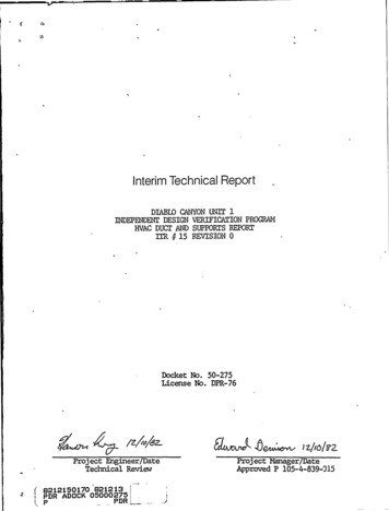
Specific RequirementsMinimum VelocityElectric heaters differ from steam or hot water coils in thatthe heat output is constant as long as the heater is energized.Therefore, sufficient airflow must be provided to preventoverheating and nuisance tripping of the thermal cutouts. Theminimum required velocity is determined from Figure 4A or 4Bon the basis of entering air temperature and KW per square footof cross sectional duct area.The maximum air inlet temperature for open coil heaters is 100 F(38 C) and for finned tubular heaters is 80 F (27 C).Example: Determine whether the minimum air velocityrequirement is met for a 10 KW open coil heater installed in a 24”wide x 12” high duct operating with 1000 cubic feet per minute(CFM) of air at a maximum inlet temperature of 65 F:1.2.3.4.Duct Area 24” x 12”/144 2 sq. ft.KW per square foot 10 KW/2 sq. ft. 5.Go to Figure 4B. Use top curve (below 80 F inlet air).Find5 KW per square foot on the vertical axis. Read minimumvelocity required, which in this case is 310 feet per minute(FPM).Heater air velocity 1000 CFM/2 sq. ft. 500 FPM.Since 500 FPM exceeds the minimum, this installation is safe.Consult your local Indeeco representative for assistance ifyou do not have sufficient air velocity.Maximum VelocityHigh velocity airflow is not normally encountered in typicalcommercial HVAC applications, when installing open coil ductheaters into velocities over 1200 feet per minute contact yourlocal Indeeco CTION22018 -910221681KW PER SQUARE FOOT DUCT AREAKW PER SQUARE FOOT DUCT AREA12BELOW800 ININLELETATIRAIR261491 -0 10INTLEAIR121086OPEN COILCONSTRUCTION4200100 200 300 400 500 600 700 800 900 1000 1100 120000MINIMUM AIR VELOCITY REQUIRED(FEET PER MINUTE)(FEET PER MINUTE)Figure 4A.4100 200 300 400 500 600 700 800 900 1000 1100 1200MINIMUM AIR VELOCITY REQUIREDFigure 4B.www.indeeco.com800-243-8162
Specific RequirementsAirflow UniformityTo prevent hot spots, airflow must be uniformly distributedacross the heater face. Figure 5 illustrates typical heatermisapplications which result in non-uniform airflow. The heater’sUL Listing requires that it not be installed closer than 4’ (122 cm)downstream or upstream from a fan outlet, abrupt transition, orother obstructions. Elbows or turns must be located at least 4’(122 cm) from inlet of the heater and 2’ (61 cm) from outlet of theheater.Heater too close to elbowHeater adjacent to transitionIf such an installation cannot be avoided, consult your localIndeeco representative for assistance. We can provide a pressureplate, non-heated zones or special low watt density coils toovercome these problems. Final approval of such applications isup to the local inspection authority.Heater partially blocked byfilter or frame memberHeater too close to fanFigure 5.www.indeeco.com800-243-81625
Specific RequirementsMultiple Heaters in the DuctClearanceIndeeco heaters are not designed for series installation in asingle duct. Since Indeeco heaters can be furnished in virtuallyany size and KW rating, series installation of heaters can beavoided.Indeeco heaters are UL Listed for zero clearance to combustiblesurfaces. Thus, there is no minimum distance betweencombustible materials and the section of duct housing theheater, or the heater itself. However, the terminal box must beaccessible for servicing. The NEC requires a minimum workspaceat least 30” (76 cm) wide by 42” (107 cm) deep for access to theheater terminal box. More space is required for large heaters andfor removal of slip-in heaters which are over 42” long.For very large heaters, field installation and shipping may besimplified by using two or more sections as illustrated by Figure6. Each section, furnished in the flanged design, has its ownset of thermal limit controls. Terminal blocks are provided tointerconnect these cutouts in the field. Sections rest stably oneon top of the other.Heaters more than 6’ (152 cm) high are normally provided insections, but larger single section heaters can be provided.Consult your local Indeeco representative for details.In addition, sufficient clearance must be provided for convectioncooling of all heaters with built-in SCR power controllers (Figure7). Allow at least 5” (12.7 cm) of free air space around the coolingfins extending from the heater terminal box. Enclosing the finsin any fashion, insulating them, or preventing them from beingcooled by normal convection may cause controller failure andvoid the heater warranty.Figure 6.Figure 7.6www.indeeco.com800-243-8162
Specific RequirementsUL and NEC RequirementsAll Indeeco electric duct heaters described in this catalog meetthe requirements of Underwriters Laboratories (UL) and theNational Electrical Code (NEC) unless otherwise indicated.†Heaters furnished with one of the Control Options on pages 10and 11 are automatically UL Listed and meet NEC requirements.Custom designed heaters must meet certain requirements tocomply with UL and the NEC. The areas of particular concern areoutlined below.Overtemperature Protection – Duct heaters must be suppliedwith both primary and secondary overtemperature protection.All Indeeco heaters are provided with both automatic andmanual reset thermal cutouts to serve this function.Airflow Interlocks – An airflow interlock must be provided tokeep the heater from operating with extremely low or no airflow.Indeeco’s standard, a built-in differential pressure airflow switchdescribed on page 15, senses static pressure in the duct as anindicator of airflow. Separate wiring to the fan motor or itscontrols is unnecessary.Alternative methods for detecting airflow include:1. The fan relay, described on page 15, provides a positiveelectrical interlock with the fan circuit.2. A separate contactor, built into the duct heater,can energize the fan when the duct heater is on.means that all, but small 120 and 277 volt single-phase open coilheaters, must be supplied with either disconnecting contactorsbuilt into the heater terminal box or into a remote panelboard.Indeeco’s standard is to supply disconnecting contactors whichbreak all ungrounded conductors in open coil heaters. Due tothe intrinsic safety of finned tubular duct heaters, UL does notrequire the use of disconnecting type contactors. Indeeco’sstandard is to supply de-energizing contactors, which break onlyone line of single-phase circuits and two lines of three-phasecircuits. Disconnecting contactors are available with finnedtubular heaters if required.Overcurrent Protection – For heaters drawing more than 48amps, the duct heater manufacturer must provide some meansof overcurrent protection either built into the terminal box or aremote panelboard. While fuses or circuit breakers are availableto meet this requirement, Indeeco’s standard is fuses.Disconnecting Means – All duct heater installations require adisconnecting means at or within sight of the heater controls.We recommend that a built-in, snap-acting, door interlockingdisconnect switch with marked “on” and “off” positions withlock-out tag-out feature be specified on all duct heaters. Thisinsures the ultimate in safety, since the heater and built-incontrols cannot be serviced without turning the disconnectswitch off. It is also far less expensive than one obtained andinstalled in the field.International Requirements3. A terminal block to allow field connection ofexternal contacts that close the circuit only whenthe fan is operating.Contactors – Contactors connected to the primary thermalcutout and airflow interlock safety circuits must be provided bythe duct heater manufacturer. Effective June 2009 UL requiresthat all open coil element duct heaters be furnished withdisconnecting type controlling, safety and backup contactorsbreaking all ungrounded conductors. Practically speaking, thisIndeeco heaters can be supplied to operate from any electricalsystem throughout the world. Single and three-phase voltagesthrough 600 volts are available. As described on pages 24through 31, all type QUA and QUZ standard heaters are availablein 380, 400 or 415 volt, three-phase ratings. All Indeeco heaterswill operate on either 50 or 60 Hz.Indeeco electric duct heaters are available with CanadianStandards Association (CSA) and Canadian Electric Code (CEC)approvals. Consult your Indeeco representative for informationand availability.† Although UL requirements are uniform throughout the country,local electrical codes may deviate from the NEC. For information onlocal requirements, consult your Indeeco representative.www.indeeco.com800-243-81627
Installation InformationHeater InstallationSlip-in heaters slide through a rectangular opening in the side ofthe duct per Figure 8. The heater is designed for 1/4” (6.35 mm)clearance around the inside of the duct. Slip-in construction isnormally preferred for ducts up to 4’ (122 cm) wide, but can befurnished for any width. The heaters are held in place with sheetmetal screws through the back of the terminal box into the duct.However, if the duct is over 3’ (91 cm) wide, supporting rails inthe bottom of the duct are recommended.Flanged heaters are attached to matching external duct flangesper Figure 9. The heaters are secured by using either sheet metalscrews or bolts and nuts through the flanges.Figure 8.A special flanged construction installed with conventional HVACslip-and-drive connectors is also available. See page 37 fordetails.Either flanged or slip-in heaters can be installed in fiberglassducts as illustrated in Figure 10. Note that a sheet metal linermust be installed into the fiberglass duct work, extending atleast 6” (152 mm) beyond the heater terminal box on both sides,more if required for structural rigidity.Field WiringBuilt-in power terminal blocks are sized for incoming copperconductors with 75 C insulation, rated to carry 125% of theheater load. However, lines may be sized to carry 100% of theheater load if a) the heater is rated at 50 KW or more, and b) theheater is controlled by a cycling device, such as a multi-stagedthermostat, step controller, or SCR power controller. Terminalblocks and knockouts on such heaters will accommodate either100% or 125% conductors. See Table I for field conductor andconduit sizing up to 500 MCM wiring. For higher amperages,terminal blocks are furnished for two or more parallel conductorsper phase.Figure 9.Fiberglass DuctSheet Metal LinerIn general, aluminum conductors are not recommended andterminal blocks are not sized for aluminum. Consult yourIndeeco representative if aluminum wire is specified for aparticular job.Sheet Metal LinerFiberglass DuctFigure 10.8www.indeeco.com800-243-8162
Installation InformationField control wiring should also be copper conductors with 75 Cinsulation. Thermostat circuits for SCR’s and step controllers areNEC Class II. Many small heaters with 24 volt control circuits arealso NEC Class II. When Class II wiring is permissible, it will beshown on the wiring schematic. Other control circuits are NECClass I.When control power is taken from the heater’s load circuit lines,Indeeco provides for the overcurrent protection of all controlcircuits, as required by NEC or UL. When control circuit poweris obtained from a separate source outside the heater, it isnecessaryfor the installer to provide overcurrent protection for all controlconductors.Table IField Wiring and Conduit Sizing* for Incoming ConductorsKW in Voltages Shown120V208V240V277V208V240V480VWire/SizeAWG orMCM1.42.42.83.34.34.99.914Sized For 100% of Heater LoadSized for 125% of Heater LoadSingle-PhaseThree-PhaseTradeConduit .0315.95002-1/23380*These tabulations are based on Table 310.15 (B) (16) of the NEC. Not more than 3 conductors in a raceway; 75 C rated copper wire.www.indeeco.com800-243-81629
Standard Control OptionsInternal WiringControl Option J – PneumaticCopper wire with a minimum of 105 C insulation is usedthroughout. Connections are made with either box lugs orconnectors crimped on with calibrated tooling. Terminal blocksare provided for all field control and power wiring.Indeeco developed the Control Option concept to maintaincompliance with changing UL and NEC requirements and to staycurrent with new duct heater temperature control systems. Theconcept has also been broadened to include numerous “SpecialFeatures” to meet a wide variety of special requirements.Control Option G – BasicControl Option G is a basic package designed for normal comfortheating applications – i.e., those that do not require pneumaticcontrol or the unique features of SCR control. With Option G, thetemperature is controlled by a pilot duty thermostat or a stepcontroller.Option J includes the following: Automatic and manual reset thermal cutouts and adifferential pressure airflow switch. The manual resetthermal cutouts always de-energize the heater load. Theautomatic reset cutout and airflow switch are normally wiredin the control circuit. PE switches to control heater staging. To minimize fieldlabor, multiple PE switches are factory-piped to a single portprojecting through the terminal box. All PE switches close onpressure rise and open upon loss of pressure to de-energizethe heater. Magnetic contactors on all Option J heaters. Fuses to protect each circuit in any heater drawing more than48 amps.Control Option G includes the following:10Control Option J is designed for pneumatic temperaturecontrol.† The contractor need only connect one air line and themain power lines to the heater. Automatic and manual reset thermal cutouts to protectagainst overheating. The automatic reset cutout is wired intothe control circuit; the manual reset de-energizes the heaterload. A differential pressure airflow switch to de-energize theheater control circuit upon loss of airflow. Magnetic contactors for each heater stage. Fuses to protect each circuit in any heater drawing more than48 amps. A control circuit transformer, with 24 or 120 volt secondaryas specified, including any overcurrent protection required byUL or the NEC. A built-in, snap-acting disconnect switch with door interlockto protect service personnel. A transformer, with any overcurrent protection required byUL or the NEC, to supply the internal control circuit of heatersrated above 277 volts.All other heaters have line voltage control circuits. A built-in, snap-acting disconnect switch with door interlockto protect service personnel.† Where more than six stages of pneumatic control are required,specify Option G with a step controller and pneumatictransducer as Special Features. Such a heater will function inthe same manner as Option J with a maximum of 20 stages.www.indeeco.com800-243-8162
Standard Control OptionsControl Option K – Proportional Control Option K is designed for the most precise temperaturecontrol, using SCR proportional power controllers and amatching electronic thermostat. For heaters above the KWratings in Table III, an electronic step controller is also provided.It works with the SCR to provide vernier proportional control.For more details on this system, see page 20. Fuses to protect each circuit in any heater drawing more than48 amps.Table III A built-in, snap-acting disconnect switch with door interlockto protect service personnel.VoltageMaximumKW120 2082402774806001 Phase 23.0 39.9 46.0 53.1 91.1 115.23 Phase—34.5 39.9—79.8 99.7In addition to these electronic components, Control Option Kincludes the following: Automatic and manual reset thermal cutouts and adifferential pressure airflow switch. The manual resetthermal cutouts always de-energize the heater load. Theautomatic cutout and airflow switch are normally wired in thecontrol circuit. However, when single-phase KW ratings donot exceed the values in Table IV, the automatic reset cutoutcarries the heater load directly and the airflow switch eithercarries the load directly or is wired into the control circuit ofthe SCR, eliminating the need for magnetic contactors.Magnetic contactors for each heater circuit. A transformer, with any overcurrent protection requiredby UL or the NEC, to supply the internal control circuit of24 or 120 volts per heater with a step controller for verniercontrol and 24 volts for all other heaters with SCR control.Wiring to remotely mounted thermostats can be Class II sincethermostat circuits are low voltage limited power circuits. A choice of room thermostat, page 12, Figure 15 or 16; ductthermostat, page 13, Figure 20 or 21; built-in PE transducer,page 13, Figure 17; or field inputs of 135 ohms, 2200 ohms,0-10 VDC and 4-20mA are available.Wiring DiagramsTypical wiring diagrams for many of the commonly usedcontrol options are located on pages 56 – 58. These diagramsof open coil and finned tubular heater constructions areintended to provide general component arrangements andwiring information. Specific wiring diagrams will be attachedto the inside of the enclosure doors for each heater and remotepanelboard and are available with certified prints. Safety magnetic contactors controlled by the automaticreset cutout, for each heater circuit, when the KW exceeds theratings in Table IV.Table IVOpen Coil HeatersSingle-Phase Voltage120208240277Maximum KW3.0——6.03.05.26.06.0Finned Tubular HeatersMaximum KWwww.indeeco.com800-243-816211
Standard Control Options ThermostatsRoom ThermostatsTwo or Three Stage, Catalog No. 1023723 Digital, with programmable 5-1-1 day program or 5-2 dayprogram, mercury freeSingle Stage, Catalog No. 1006998 Non-digital, non-programmable, snap-acting bimetal,mercury free, SPST, with positive off single stage Range: 50 to 90 F (7 to 32 C) HEAT-OFF-COOL-AUTO EMERGENCY HEAT and fan AUTOON selections Easy to read backlit display Accuracy: 3 F ( 1.5 C) Range: 40 to 90 F (4.5 to 32 C) Color: White Accuracy: 1 F ( 0.5 C) Inductive Rating: 1.2 amp at 30 volts max Color: White Offered with duct heater selection Inductive Rating: Hardwire, three or four wire heat onlyClass II circuit, 1.0 amp at 30 volts maxFigure 11.Single Stage, Catalog No. 1023721 Digital, with programmable 5-1-1 day program or 5-2 dayprogram, mercury freeFigure 14. HEAT-OFF-COOL-AUTO and fan AUTO-ON selections Easy to read backlit displayElectronic Proportional, Catalog No. 1007101 Range: 40 to 90 F (4.5 to 32 C) Tamperproof construction Accuracy: 1 F ( 0.5 C) Range: 40 to 90 F Color: White Inductive Rating: Hardwire, two wire heat only Class IIcircuit, 1.0 amp at 30 volts max Type: Ohmic – 2200 ohms For use with Indeeco controllers Special OrderFigure 12.Figure 15.Two Stage, Catalog No. 1007030Electronic Thermostat, Catalog No. 1031404 Digital, non-programmable, mercury free TA167 Thermostat is proportional 1-10 VDC COOL-HEAT-OFF EMERGENCY HEAT and fan AUTO-ONselections Range: 50 to 90 F For use with Indeeco controllers Easy to read backlit display Range: 40 to 90 F (4.5 to 32 C) Accuracy: 1 F ( 0.5 C) Color: White Inductive Rating: Hardwire, three wire heat only Class IIcircuit, 1.0 amp at 30 volts maxFigure 16.Figure 13.12www.indeeco.com800-243-8162
Standard Control Options ThermostatsPE TransducerCatalog No. 1020887 Built into heater terminal boxTwo Stage Light Duty, Catalo
pricing and sizing of open coil and finned tubular duct heaters within minutes. With this software, your local Indeeco representative becomes the source for . Electric heaters differ from steam or hot water coils in that the heat output is constant as long as the heater is energized. Therefore, sufficient airflow must be provided to prevent .