Transcription
Version 5.0Heating System Example
MetaCase Document No. PLC-5.0Copyright 2012 by MetaCase Oy. All rights reservedFirst Printing, 2nd Edition, September 2012MetaCaseYlistönmäentie 31FI–40500 JyväskyläFinlandTel:Fax:E-mail:WWW: 358 14 641 000 358 420 648 606info@metacase.comhttp://www.metacase.com
No part of this manual may be reproduced or transmitted in any form or by any means,electronic or mechanical, including but not limited to photocopying, without express writtenpermission from MetaCase.MetaEdit is a registered trademark of MetaCase. The other trademarked and registered trademarkedterms, product and corporate names appearing in this manual are the property of their respectiveowners.
DSM for heating systemsPrefaceThe heating system example illustrates how heating applications can be modeled andgenerated based on Domain-Specific Modeling (DSM). To achieve this, two integrateddomain-specific modeling languages are implemented into MetaEdit along with a generatorfor producing PLC code. Using these modeling languages, a developer can design heatingapplications using directly the domain concepts of the domain, like pipes, pumps, valves,pressure sensors and their related behavior like opening or closing valves. Generators are usedto produce the executable code, integrated into a PLC software development environment(TwinCAT). Generators are also used for producing installation guidelines, documentation,and model checking.The rest of this document describes the language and generators for the developing heatingsystems as well as how they were implemented with MetaEdit . First, we inspect shortly themodeling languages with some examples and then we discuss selected topics on modelinglanguage and generator specification. These topics are set by the LWC2012 challenge(http://languageworkbenches.net).For exploring the heating system example thoroughly, the following things are required: MetaEdit for trying out the languages and generators. The PLC heating system examplecan be found from the demo repository, from the project named ‘Heating system’. Forfurther information about MetaEdit , please refer to the MetaEdit User’s Guide1. Beckhoff TwinCAT software system for running the generated application. TwinCAT candownload from .htm.TwinCAT 2.11 R2, Build 2038. There may also be newer versions available.DownloadWe expect that you have knowledge about using MetaEdit . If you want to extend the DSMfurther add notational symbols, additional constraints, generators or by modifying dialogsand toolbars for the modeling tool you should have MetaEdit Workbench or the evaluationversion available from http://www.metacase.com.14MetaEdit User Guides, t
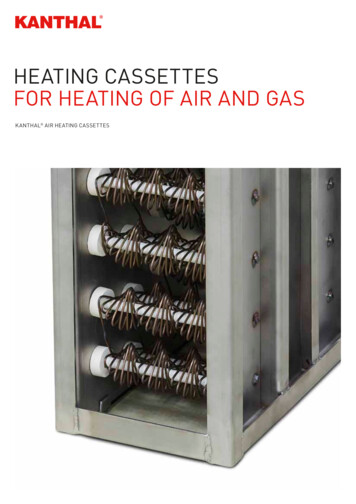
DSM for heating systems1DSM for heating systemsFor modeling heating applications the MetaEdit supported modeling solution provides twointegrated languages and a number of generators. In addition to editors, MetaEdit providesalso various browsers, predefined generators, multi-user support, etc [1].The main window for browsing the models and accessing the editors and generators is shownbelow. The opened ‘Heating system’ project contains one P&I Diagram describing the pipingand instrumentation and five heating applications which run in the controllers.Figure 1-1. MetaEdit main window showing the contents of heating system projectHeating system example5
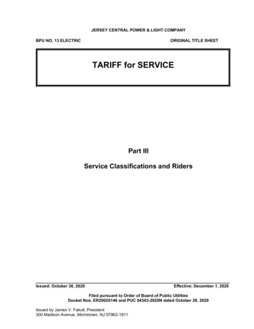
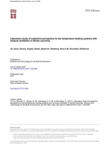
DSM for heating systems1.1 SYSTEM STRUCTUREP&I Diagram specifies pipe connections among the various instruments. Those instrumentswhich have controllable behavior are specified in a subdiagram using another domain-specificlanguage.Figure 1-2. Structure: Pipes and Instrumentation1.2 CONTROL BEHAVIORHeating application language specifies the control logic of the system: states of the controller,conditions based on instrument data and various actions to control the instruments. Theinstruments are the same as in the P&I Diagram and they can be accessed from both types ofdiagrams.6MetaEdit
DSM for heating systemsFigure 1-3. Behavior of boiler controller1.3 GENERATORSGenerators are available for both languages. Most important generators are those for P&IDiagram: ‘expFiles’ produces the code in the format of TwinCAT exp.files. The generated codeprovides the control logic blocks, its simulation as well as additional resources, likedatatypes and task structures. The generated code follows the same style andconventions as the reference implementation.‘TwinCAT’ provides integration with TwinCAT PLC control tool: the code, asproduced by ‘expFiles’ is imported into TwinCAT PLC control tool, migrated withthe platform providing the basic building blocks and compiled forexecution/simulation.‘Installation’ produces HW installation guide in HTML listing the type of instrumentsand the amount of pipe needed (calculated from the length of individual pipes).‘Doc’ generates documentation of the system into a Word document.In addition to these generators other generators are defined for model checking (shown in thebottom of Diagram Editor), generating interface descriptions as well as producing textualdescription of the piping for those who prefer text instead of diagrams.Heating system example7
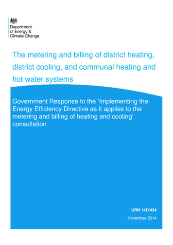
Implementing the DSM language for the heating system domain2Implementing the DSM language forthe heating system domainThis section describes how domain-specific modeling languages and generators areimplemented in MetaEdit .2.1 DEFINING LANGUAGE ELEMENTSElements of the modeling language can be defined in MetaEdit with a graphicalmetamodeling language or with form-based metamodeling tools. We outline here these toolsused to define languages for heating systems. For a complete description of these tools, seeMetaEdit Workbench User’s Guide2.2.1.1 Graphical metamodelingLanguage elements, abstract syntax part of the language, can be defined with a graphicalmodeling language. Figure below shows the partial metamodel of a language used to specifycontrol behavior of the central heating system: state transitions of the ‘Heating application’modeling language. A blue rounded rectangle symbol indicates an object type or a set ofobject types, an orange diamond symbol shows the ‘transition’ relationship type and a greencircle is used to describe the role types.28MetaEdit Workbench Guide, t
Implementing the DSM language for the heating system domainFigure 2-1. Metamodel of heating application language (partial)After the metamodel, as above, is drawn in Diagram Editor of MetaEdit it can be instantiatedand tested immediately with the modeling editors providing full editor functionality(copy/paste (special ), undo, replace, trace, print etc.). Once the language definition iscomplete it can be given for the developers using MetaEdit Modeler.2.1.2 Form-based metamodeling toolsForm-based metamodeling tools define all aspects of the language: not only abstract syntax,but also language rules, notation and generators for model checking, code generation,documentation generation etc. The form-based tools are integrated allowing to access andtrace between all the language elements: e.g. from abstract syntax to notational symbols, fromgenerator definition to metamodel, from debugged generator to models etc.Most importantly, the definition of language elements is automatically applied in the variousmodeling editors (Diagram, Matrix, Table), browsers (Graph, Object, Type) and generators.This supports agile and incremental language definition: updates to the modeling language canbe tested immediately and shown for the language users.Heating system example9
Implementing the DSM language for the heating system domainLanguage concepts (abstract syntax)Graph tool defines the individuallanguages. Here a definition for a‘P&I Diagram’ is given. Adiagram itself has properties, andeach property has a moredetailed definition. For example,‘System name’ is an identifying(marked with ‘*’) property. It isof string data type and its valuemust be unique: there can’t beother P&I Diagrams with thesame name.The Graph Tools includes also adescription field to document thelanguage. The description givenis used in the language helpavailable in the modeling editors(Help Graph Type ).Types tab in the Graph Toolshows the individual languageconcepts:objecttypes,relationship types and role types.These different type of conceptscan be here added or removedfrom the language.10MetaEdit
Implementing the DSM language for the heating system domainFor each type, a formbased metamodelingtoolshowsitsdefinition.HereObject Tool shows thedefinitionofa‘Sensor’: its name,ancestor type, n.Other kind of types,like property types,port types, role typesand relationship typesare defined similarlywith the form-basedmetamodeling tools.A definition of ‘Sensor name’is shown in Property Tool. Itis of String data type, usesInput Field for entry, does nothave any default value andmust have a mandatory value.The constraint on mandatoryvalue is specified using theregular expression (‘. ’).Heating system example11
Implementing the DSM language for the heating system domainSubgraph tab in GraphTool sets the linksbetweenthegraphscreated. The linked graphsmay be of different type asin case of heating systems:A behavior of a Pump forexample can be describedin another kind of a graph(called here ‘Heatingapplication’).Constraints are specified with the form-based tools as a part of the metamodel or defined withthe generators. Below some implemented constraints are shown for the P&I Diagram. Theconstraints are given as data and entered by choosing from the existing set of constraint types.For example, ‘System end’ may be connected to one ‘Pipe’ relationship only.Figure 2-2. Defining constraints of the language12MetaEdit
Implementing the DSM language for the heating system domainNotationThe notation of the DSL is defined with Symbol Editor. It can be opened from the form-basedtools while defining the language abstract syntax. Below Symbol Editor shows the symbol for‘Boiler’ Object Type.Figure 2-3. Symbol definition for the BoilerThe notational symbol of ‘Boiler’ consists of multiple symbol elements, and each symbolelement can be drawn here, selected from the symbol library, or retrieved from other elementsused in the models. Individual symbol elements can be made conditional depending on themodel data.The symbol of ‘Boiler’ consists of two ellipses, a polyline, and a text property showing thename of the boiler. The symbol definition also shows three different kinds of connectables:how bindings can be drawn connecting the ‘Boiler’ with a ‘Pipe’ to other instruments. ‘Boiler’has two heat connectables specifying ‘Pipe’ connections for hot (input) and cold (output). Thethird main connectable is used to draw connections for instruments using the heated water,liquid etc.Symbol Editor allows importing existing symbols, or their parts, as vector graphics orbitmaps. Symbol Editor may also retrieve the symbols from the in-built Symbol Library ofMetaEdit .GeneratorsMetaEdit Generator System is used to define generators for various needs. In case of heatingsystems, generators are used to produce code, model checking, installation guide in HTML,Word documentation of the system, as well as importing the generated code directly intoTwinCat environment.MERL, a domain-specific language for generator development, is used to define generators.Figure below shows the MERL definition for function block generation in Generator Editorfor P&I Diagram. The generator script is shown bottom of the window, a hierarchy ofHeating system example13
Implementing the DSM language for the heating system domaingenerator modules on the top-left, MERL templates in the top-middle, and DSL elements(metamodel) on the top-right compartment of the window.Figure 2-4. Generator definition in MERLGenerator Editor supports syntax highlighting, static code analysis, error detection, navigationamong the subgenerators and content assistant showing the metamodel structures whilewriting the generator. MetaEdit provides also full MERL source-level debugger withbreakpoints, interrupts, conditional breakpoints, live editing of variables etc. In addition to theGenerator System, MetaEdit offers API based on webservices/.Net/SOAP for accessing themodel elements using other generator systems.The form-based metamodeling tools also support definition of user-interface elements (toolbarand browser icons, property editing dialogs and visible element identifiers) in case the onesprovided by default are not considered adequate by the language engineer.14MetaEdit
Implementing the DSM language for the heating system domain2.2 DEFINING A P&I NETWORK OF THE HEATING SYSTEMAt any point of time during the language definition, created languages can be tried out inMetaEdit using the ready editors, browsers, multi-user support, printing functions etc. Thisenables fast prototyping and incremental development of the DSM support.Diagram below follows closely the visualization proposed in the LWC2012 assignment. Forexample, pipes which are marked to be thermally insulated are shown with thick lines, pipeswhich are jacketed are shown with double lines, and pipes which don’t have any cover areshown with thin solid lines. This visualization was defined with the Symbol Editor.Figure 2-5. Instruments and their pipe connectionsDiagram Editor shows the description of the LWC2012 heating system using the developedDSL. Second toolbar shows the main concepts of the DSL. Creation of the model has beenmade by choosing the domain concept from the toolbar and then adding it to the canvas.During model creation and editing Diagram Editor checks that the DSL definition is followed:either by checking the definition of the metamodel or by running the checking scripts writtenin MERL.Heating system example15
Implementing the DSM language for the heating system domain2.3 IMPROVED VISUALIZATION OF THE P&I NETWORKWhile the notation shown above follows the well known and widely used notation of Pipingand Instrumentation, it has been enhanced with optional coloring and error annotation. Figurebelow shows the same heating application using these visualization enhancements. Thesevisualization options can be set on or off from the graphs property ‘Use visualization’.Figure 2-6. Visualizing nstruments in P&I DiagramThe editor also shows possible errors and incompleteness information as defined by thelanguage engineer. Here two errors/warnings are reported: Sensor has only one connection andValve has connection to one pipe only. By clicking the elements in the error report MetaEdit traces and selects the elements in the diagram to be updated.While the P&I network is shown graphically it can also be presented textually for those whoprefer textual specifications. Textual specifications can be generated (Graph Generators )from the diagram and the properties of the individual pipes and instruments can be accessedfor editing from the text.16MetaEdit
Implementing the DSM language for the heating system domain2.4 CONTROL BEHAVIOR OF THE HEATING SYSTEMBehavior is defined with another graph type: ‘Heating application’. The behavior descriptionis defined for each relevant instrument of the P&I Diagram. Diagram Editor below shows thebehavior of the ‘Pump’ P1. The language is based on a state machine, but is domain-specificby accessing conditions from the instruments only (like ‘Boiler’s’ flame detection) as well asby being able to set actions for certain instruments only (like put ‘Pump’ on or off).Figure 2-7. Behavior of pump controllerThe behavioral model refers directly to the instruments defined in the P&I Diagram. In otherwords, an instrument is the same in both kinds of diagrams – no need to update a change inmultiple places or keep string values matching. Diagram Editor (as well as other editors andbrowsers) allows tracing between these two kinds of diagrams as well as see how instrumentsare (re)used. By selecting Info from the elements pop-up menu you can see the possiblereuse cases. The languages support also checking consistency of the different diagrams. Forexample, if behavioral model uses instruments that are not defined in structural piping andinstrumentation model they are reported as errors/warnings in the P&I Diagram.For more complex conditions and comparisons the language has own constructs whichavailable from the toolbar similarly to all other language constructs. Below a diagram for HeatController shows a constraint based on ‘Radiator’ R1 and ‘Boiler’ B1 warming. The exampleshows also entry and exit actions. While they are not necessarily, as the same functionalitycould be specified via state transitions too, they were added to the heating applicationlanguage to mirror closely the reference implementation.Heating system example17
Implementing the DSM language for the heating system domainFigure 2-8. Behavior of heating controller2.5 SPECIFYING INTERLOCK/CONSTRAINT DEFINITIONS OFTHE CENTRAL HEATING SYSTEMUsually the best place to define invariants is in the definition of a modeling language itself orin the generator. This way language user always follows the constraints - even withoutknowing about them. Therefore the interlock/constraint definition can be supported similarlyas done in Section 2.1, defining language elements.If there is a need to model the interlocks/constraints then one solution would be defining themwith the DSL too. That DSL would be still integrated with the other DSLs. An example ofinvariant is that if the burner is on then the pump must be running. Below such rule is definedwith emergency shutdown action: if pump is not on and the burner is running then burner isput off. Other constraints could be added to the language too, but here already available DSLconstructs can be used to describe invariants/constraints.18MetaEdit
Implementing the DSM language for the heating system domainFigure 2-9. Modeling invariant/interlocks with the DSL2.6 GENERATING STRUCTURAL DEFINITIONS AND STUBSFOR A TARGETStructural definitions include for example the data types of component types as well as variouscontroller states. These are generated as a part of whole code generation process availablefrom the toolbar of P&I Diagram. A sample of the generated data type code for radiatorcontroller is shown below.TYPE E MDL RadiatorController SM States :(* RadiatorController states generated from MetaEdit *)((**** Initial States ****)MDL RadiatorController SM Initial,(**** Normal States ****)MDL RadiatorController SM INITIALIZING,MDL RadiatorController SM MONITOR ROOM TEMPERATURE);END TYPEIn addition to the code, other structural definitions are generated too. Figure below shows thegenerated installation guide describing the instruments needed as well as counting how muchpipe is needed.Heating system example19
Implementing the DSM language for the heating system domainFigure 2-10. Generated installation documentation20MetaEdit
Implementing the DSM language for the heating system domain2.7 GENERATING CONTROL CODE FOR A TARGETAll the code needed for the heating application, including those providing structuraldefinitions as well as those generating function blocks with behavioral code are generated viaa single main generator. In other words, the generator for the whole heating system calls thegenerators for structural data, logic, simulation, tasks etc.To apply the generators choose Graph Generate and select ‘TwinCAT-autobuild’ orpress ‘TwinCat’ button in toolbar of the Diagram Editor for P&I Diagram. The code generatedwith TwinCAT-autobuild option uses the platform of the homeheating system. This platformincludes the basic building blocks which the code generated from the models uses.In this example the generator also produces the platform: it is a part of the generator (onesubreport in the ‘TwinCAT-autobuild’ generator). In practice the platform would be a separateproject file in TwinCAT. During the autobuild generation TwinCAT is started, code isimported and compiled for execution. When creating the project TwinCAT asks to choose thetarget system. Select PC. If you just want to see the generated code, select generator‘expFiles’.A sample of the generated code from the Heat Application behavior is shown below. The codeis generated to mimic closely the approach used in the reference implementation. It isgenerated from ‘Heating application’ diagram HeatController (see Section 2.4 above).Heating system example21
Implementing the DSM language for the heating system domainACTION MDL HeatController SM rg:(* HeatController state machine generated from MetaEdit *)MDL HeatController SM bIsEntry : MDL HeatController SM bATransitionWasPerformed;IF MDL HeatController SM bIsEntry THENMDL HeatController SM eLastState : MDL HeatController SM eCurrentState;MDL HeatController SM bATransitionWasPerformed : FALSE;END IFCASE MDL HeatController SM eCurrentState OFMDL HeatController SM Initial:IF NOT MDL HeatController SM bATransitionWasPerformed THENMDL HeatController SM eCurrentState : MDL HeatController SM INITIALIZING;MDL HeatController SM bATransitionWasPerformed : TRUE;END IFMDL HeatController SM CONTROL BURNER:IF MDL HeatController SM bIsEntry THENMDL HU B1.On(); MDL HU CV2.Open();END IFIF NOT MDL HeatController SM bATransitionWasPerformed THENIF NOT (MDL R1.bWarmUp OR MDL B1.bWarmUp) THENMDL HeatController SM eCurrentState : MDL HeatController SM WAIT FOR HEAT REQUEST;MDL HeatController SM bATransitionWasPerformed : TRUE;END IFEND IFIF MDL HeatController SM bATransitionWasPerformed THENMDL HU B1.Off(); MDL HU CV2.Close();END IFMDL HeatController SM INITIALIZING:IF MDL HeatController SM bIsEntry THENMDL HU B1.Off(); MDL HU CV2.Close();END IFIF NOT MDL HeatController SM bATransitionWasPerformed THENMDL HeatController SM eCurrentState : MDL HeatController SM WAIT FOR HEAT REQUEST;MDL HeatController SM bATransitionWasPerformed : TRUE;END IFMDL HeatController SM WAIT FOR HEAT REQUEST:IF NOT MDL HeatController SM bATransitionWasPerformed THENIF MDL R1.bWarmUp OR MDL B1.bWarmUp THENMDL HeatController SM eCurrentState : MDL HeatController SM CONTROL BURNER;MDL HeatController SM bATransitionWasPerformed : TRUE;END IFEND IFELSEF Assert(FALSE, 'Wrong MDL HeatController SM rg state identifier');END CASEEND ACTION22MetaEdit
Implementing the DSM language for the heating system domain2.8 GENERATING A MOCK REPRESENTATION (SIMULATION)OF THE DEFINED HEATING SYSTEM‘TwinCAT-autobuild’ and ‘expFiles’ generators produce also the simulation for TwinCAT. InTwinCAT System Manager, after importing the created project info (.tpy), you must link theinputs and outputs of the produced application into those used for simulation and generate themappings in TwinCAT System Manager. After that you can run the generated simulation.2.9 GENERATING INTERFACE FOR HIGHER LEVELSOFTWAREGeneration of interface code is done similarly to any other generator of MetaEdit : writing itwith MERL accessing the same heating application models. An example of such interfacecode generation is made for accessing data and transmitting values from the sensors.A sample of the generated API code is shown below. Here the API includes only those sensorsthat are available for the given heating system (see P&I Diagram in Section 2.3). You can runthe generator from Editor for P&I Diagrams by selecting Graph Generate and thenselecting ‘Sensor Interface API’.Sensors of HomeHeating can be accessed with the following API:long getTemperature (string SensorID);(returns the current temperature data from the named sensor)long getFlow (string SensorID);(returns the current flow data from the named sensor)long getSpeed (string SensorID);(returns the current speed data from the named sensor)void transmitTemperature (string SensorID);(transmits the temperature from the named sensor)2.10 VISUALIZING THE DYNAMIC BEHAVIORTwinCAT provides a possibility to visualize the running system. This approach can be appliedwith the code generated with MetaEdit as well. The figure below shows a snapshot of thesimulation for the generated heating application. Here the visualization elements are thoseavailable from TwinCAT.Heating system example23
Implementing the DSM language for the heating system domainFigure 2-11. Visualizing the heating system in TwinCatAn alternative approach, and often a better one, is to use MetaEdit directly to visualize theexecution. In other words, MetaEdit animates P&I Diagram or visualizes the behavioral partof the system by animating the state changes of the controllers. The advantage of thisapproach is that there is no need to create duplicate models of piping and instrumentation (asabove) or of behavior for the simulation purposes. Most importantly, this way MetaEdit provides direct model-level debugging using the original models as visualizations: ifsomething was found wrong during the simulation, engineers can correct the simulateddiagram and run the generators again.To visualize dynamic behavior in MetaEdit , the target system (TwinCAT or even the realtarget system depending on its capabilities) can call the MetaEdit API. For example, with theAPI’s animate command the pipes, instruments, and states could be animated directly inDiagram Editor of MetaEdit . MetaEdit ’s API is based on SOAP / Web Services / .NETstandard for application integration that is available for almost any programming language andoffice tools (e.g. Excel). The implementation of visualization support from TwinCAT is left tothe reader as MetaEdit already provides capabilities for visualization. To use MetaEdit enabled visualization, the generated code would include object identifiers that MetaEdit usesfor model elements. Therefore, the generator developer defines which model elements shouldbe visualized: instruments of the structural models or states, actions etc. defined in thebehavioral models. MetaEdit API is not restricted to animation only as it can be used also tomodify, create and delete the elements in models as well as the representation of the modelelements.24MetaEdit
Conclusions3ConclusionsIn this example, we have demonstrated a DSM for PLC heating system applicationdevelopment. With the domain-specific language we can model heating applications using twolanguages: one language targets the structure of the system specifying how instruments areconnected with pipes, and another, yet integrated language, describes the behavior of thevarious controllers.On the DSM definition side we focused on several a few areas of language design: integratedtwo languages, generating the code so that it integrated with an existing PLC developmenttool, and producing various other artifacts like installation guide, sensor API and modelchecking.This DSM solution is implemented as any other modeling language and generator inMetaEdit . It is completely open and thus it can be freely extended to cover additionalrequirements of modeling or code generation. You could for example extend the framework,change the domain rules in the language, or produce other kind of code than the current statebased PLC code. The choice is yours because with DSM you control both the language as wellas the generators.Heating system example25
Implementing the DSM language for the heating system domain Heating system example 13 Notation The notation of the DSL is defined with Symbol Editor. It can be opened from the form-based tools while defining the language abstract syntax. Below Symbol Editor shows the symbol for 'Boiler' Object Type. Figure 2-3. Symbol definition for the Boiler