Transcription
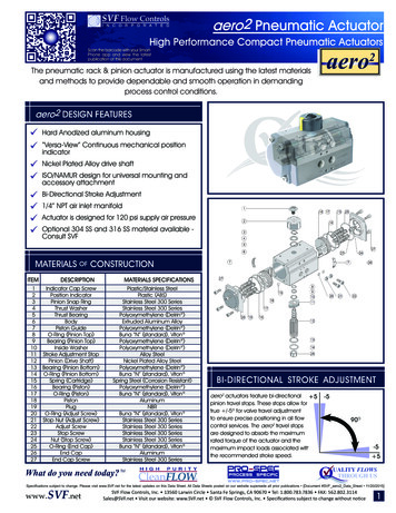
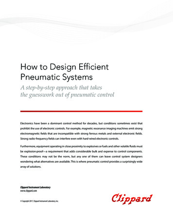
Top Quality Valve ActuatorsMade in SwedenRC88InstructionPneumatic actuatorsType and designAccording to Fig.4:DAAO-Actuator with adjustable open valve position (counter clockwise end of travel).SR-Actuator with spring closing (clockwise direction),adjustable “open” valve position (counter clockwise end oftravel).The possibility to turn the pistons can be used in severalways in order to suit the actuators to the customer’srequirements.DA Double Acting actuator with pneumaticoperation in both directions.SR Spring Return actuator with spring return.Operating mediumIf the operating medium is instrument air, it shall bedustand oil-free. Accepted operating medium: Non-dangerous fluids (group 2 according to directive 97/23/EC).The dew point shall be equal to –20 C or, at least, 10 Cbelow the ambient temperature. The maximum particlesize must not exceed 40 μm. The exhaust air must passthrough a filter silencer before it is let out into the workshop.Installation and adjustmentWARNING!RC actuators must only be used as actuators on valves.Levers, racks and similar cannot be used to transmitmovement without protective equipment.Hand operationAll types of actuators can be mounted in various positions,e.y. vertical or horizontal. When mounting on a valve,ensure that the actuator shaft and the valve stem are centered, and that a play of ca. 1–2 mm exists between shaftand driving bush. After mounting, it may be necessary toadjust the turning angle of the actuator.WARNING!It is very risky to try to operate the actuator manually byusing the key grip on the driving shaft. The accumulatedenergy inside the actuator may instantaneously be setfree.Tightening torques for screws and lock nuts onpage 6.The actuator can be equipped with disengagable gearboxon the underside of the actuator for manual operation.As mentioned previously, the DA actuators can, asstandard, be adjusted in ”closed” valve position and theSR actuators in ”open” position. The adjustment occursby loosening the lock nut on the end plate and turning theset screw clockwise for reduced and anti-clockwise forincreased rotary motion. The adjustment degree is 3 .RC88 has 4 adjustment screws. It is important that allscrews are in contact with the piston in question.WARNING!All manual operation must be carried out using a ventedactuator.The possibilities of the Scotch YokeconstructionWARNING!The Scotch Yoke of the RC actuators has canted slots.Thus the actuator can be given different function depending on how the pistons are mounted in the actuator. Thepistons are mounted according to Fig.1, page 3, or Fig.4,in order to achieve the following functions.According to Fig.1:DA-Actuator with adjustable closed valve position (clockwise end of travel).SRF-Actuator with spring opening (counter clockwisedirection), adjustable “closed” valve position (clockwiseend of travel).Pinch risk in the valve opening when test runningnon-installed valves.www.remotecontrol.seRemote Control SwedenTel 46 (0)23 587 00Fax 46 (0)23 587 45www.remotecontrol.seinfo @ remotecontrol.seRemote ControlTel 49 (0)2131 795 760Fax 49 (0)2131 795 76115www.remotecontrol.deinfo @ remotecontrol.deRemote Control LtdTel 44 (0)1889 576 888Fax 44 (0)1889 577 676www.remotecontrol.co.ukinfo @ remotecontrol.co.uk-1-Remote Control AsiaTel 65 6848 7150Fax 65 6746 5815www.remotecontrol.com.sginfo@ remotecontrol.com.sgRemote Control IncTel 1 (0)401 294 1400Fax 1 (0)401 294 3388www.rciactuators.cominfo@ remotecontrol.us
Service of RC88LubricationWARNING!RC actuators are permanently lubricated and additionallubrication is normally not required. Howewer, for actuators performing 100,000 operation cycles or more undervery heavy load, an oil mist lubrication is recommended.Oil mist lubrication requires a mineral oil type ISO VG32acc. to DIN 51524 HLP for usage in temperature range–10 to 70 C. Oil mist lubricator must be set at lowestpossible value. Commenced oil mist lubrication must continue. If the actuator is equipped with pneumatic or electropneumatic positioner, oil mist must not be used.Before dismantling, check that the compressedair and possible power supply are disconnected.Dismantling of SR unit: See instruction on page 5.Exchange of piston sealings andsupport element1.2.3.4.Please read the warning above!Dismantle the actuator from the console.Dismantle the end plates (5) or the spring houses (25).Fasten the actuator shaft between soft jaws in a viceand turn the actuator until the pistons reach the cylinder end.Then place a few rods in the holes on theoutside of one piston. By pressing together and pullingthese rods simultaneously, the piston is dismantledfrom the cylinder.5. If the O-rings (12) are worn, they must be replaced.6. Replace the support band (14) if it is worn.7. Replace the support element (9) if it is worn. If it hasbeen glued, the whole piston is replaced.8. Grease the cylinder surfaces with a high qualitygrease, for instance a ball bearing grease.9. Mount the pistons.10. Mount the end plates and adjust the turning angle .Recommended Lubrication GreaseCylinderbore anddrive shaftwith shaft sealingsGreaseRC88 StandardKlübersynth AR 34-402RC88 high tempKlübertemp HM 83-402RC88 low tempKlüber Isoflex Topas NCA 52Piston roller (21) bearingAll RC88GreaseCargo Red GreaseOil mist lubrication and grease containing polyglycole,ester or other aggressive additives shall be avoided.Converting to SR actuatorsExchange of shaft sealings andsupport washersThe O-rings (18) and the support washers (33) can easilybe replaced as below.1. Please read the warning above!2. Dismantle the actuator from the console.3. Dismantle the retaining rings (31) around the shaft.4. Dismantle worn details.5. Fit the new O-rings (18).6. Fit new washers (32) and (33) under the retaining rings.7. Use a grease according to the lubrication list whenmounting.8. Fit the new retaining rings.9. Check that the retaining rings are tightly fitted withoutplay in their grooves.Exchange of shaft bearingsThe bearings (16) can easily be replaced when the pistonsand shaft sealings are dismantled as above.All DA-actuators can be changed into SR actuators byadding spring conversion kits according to the following:1. Please read the warning above!2. Dismantle the end plates.3. Dismantle the pistons. See ”Exchange of pistonsealings and support element”.4. Mount the pistons according to fig. 4 on page 3.5. Check that the spring is correctly pre-tensioned. The”A” measure in fig. 3 should be 137 mm.6. The spring guide (22) is centered towards the pistonwith the aid of 2 pins.7. The SR units must be turned so that one of the threesupport points lies between the bosses on the piston(10).8. Mount the SR unit when the pistons are in their innermost positions.9. Put the screws (4) in place. When tightening thescrews, the spring force is transmitted from the tensioning screw (26) to these screws. Tighteningtorques according to page 6.10. The turning angle of the actuator is adjusted with thetensioning screws (26). It is important that all screwsare in contact with the piston in question.www.remotecontrol.seRemote Control SwedenTel 46 (0)23 587 00Fax 46 (0)23 587 45www.remotecontrol.seinfo @ remotecontrol.seRemote ControlTel 49 (0)2131 795 760Fax 49 (0)2131 795 76115www.remotecontrol.deinfo @ remotecontrol.deRemote Control LtdTel 44 (0)1889 576 888Fax 44 (0)1889 577 676www.remotecontrol.co.ukinfo @ remotecontrol.co.uk-2-Remote Control AsiaTel 65 6848 7150Fax 65 6746 5815www.remotecontrol.com.sginfo@ remotecontrol.com.sgRemote Control IncTel 1 (0)401 294 1400Fax 1 (0)401 294 3388www.rciactuators.cominfo@ remotecontrol.us
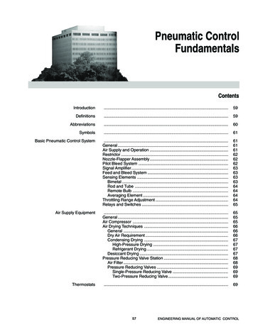
Fig. 1RC88-DA actuator. Upper cylinder from above.Drawing 007188AUpper sideFig. 3Drawing 007195AFig. 2Fig. 4RC88-SR actuator. Upper cylinder from above.Drawing 007180BDrawing 007192Awww.remotecontrol.seRemote Control SwedenTel 46 (0)23 587 00Fax 46 (0)23 587 45www.remotecontrol.seinfo @ remotecontrol.seRemote ControlTel 49 (0)2131 795 760Fax 49 (0)2131 795 76115www.remotecontrol.deinfo @ remotecontrol.deRemote Control LtdTel 44 (0)1889 576 888Fax 44 (0)1889 577 676www.remotecontrol.co.ukinfo @ remotecontrol.co.uk-3-Remote Control AsiaTel 65 6848 7150Fax 65 6746 5815www.remotecontrol.com.sginfo@ remotecontrol.com.sgRemote Control IncTel 1 (0)401 294 1400Fax 1 (0)401 294 3388www.rciactuators.cominfo@ remotecontrol.us
Material table for RC88Part 3132333441515354555657585960DescriptionAdjusting screwLock nutO-ring1ScrewEnd plateO-ring1Cylinder, upperScotch YokeSupport element1PistonLocking screwO-ring1Support band1Driving shaftBearingO-ring1Support ringPiston shaftPiston rollerSpring steeringSpring, externalSpring, internalSpring housingPre-tensioning screwIndicatorO-ring1Lock nutMarking washerRetaining ring1Middle washer1Support washer1Sealing plugNutGuide ringSpacerSpacing sleeveGuide pinO-ring1O-ring1Plane sealing1ScrewCylinder, lowerNo. 88-DA44432441244244144444122222142818441No. teelPOM/PTFEAluminiumSteelNitrilePTFE, filledSteelPolymer materialNitrilePolymer materialSteelSteelAluminiumSpring steelSpring steelAluminiumSteelPolymer materialNitrileSteelAluminiumSpring steelStainless spring steelStainless spring steelNitrileSteel/nylonAluminiumStainless steelStainless steelStainless ace treatmentZinc platedZinc platedZinc platedPowder coatedAnodizedCorrosion protectedChemically zincHardenedHardenedCorrosion protectedCorrosion protectedPowder coatedZinc platedZinc platedAnodizedCorrosion protectedZinc platedAnodizedCorrosion protectedZinc platedAnodized1) Included in seal kit.www.remotecontrol.seRemote Control SwedenTel 46 (0)23 587 00Fax 46 (0)23 587 45www.remotecontrol.seinfo @ remotecontrol.seRemote ControlTel 49 (0)2131 795 760Fax 49 (0)2131 795 76115www.remotecontrol.deinfo @ remotecontrol.deRemote Control LtdTel 44 (0)1889 576 888Fax 44 (0)1889 577 676www.remotecontrol.co.ukinfo @ remotecontrol.co.uk-4-Remote Control AsiaTel 65 6848 7150Fax 65 6746 5815www.remotecontrol.com.sginfo@ remotecontrol.com.sgRemote Control IncTel 1 (0)401 294 1400Fax 1 (0)401 294 3388www.rciactuators.cominfo@ remotecontrol.us
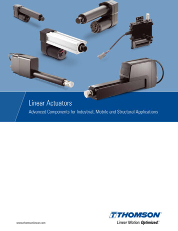
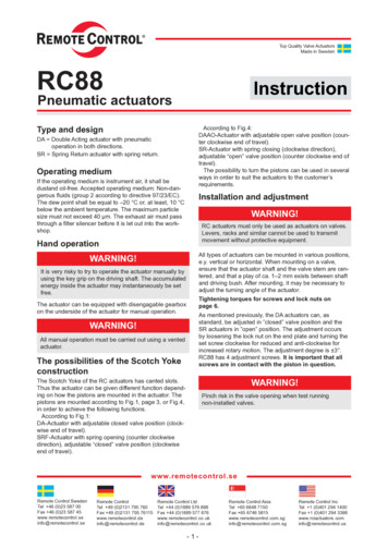
Instructions for dismantling of RC88-SR actuatorsFig. 5Drawing 007196AFig. 6Drawing 007198A6. Turn the upper left tensioning bolt (26) anticlockwiseuntil it lies against the spring steering (22) accordingto figure 6 and dismantle the left spring housing byloosening the screws (4).7. Dismantle the upper right spring housing by using thesame method as with the left one.8. Dismantle the lower spring housings in the same manner as the upper ones.9. Dismantling must be carried out with the utmost care.In the case of the slightest uncertainty – contact thesupplier!VARNING!This procedure must be followed for safe dismantling ofpretensioned spring housings.1. Check that the springs can press the piston intostarting position according to figure 5.2. The actuator must be pressureless.3. Disconnect all possible power supply.4. Loosen the lock nuts (29).5. Turn tensioning bolts (26) clockwise until they canbe turned with the minimum force.www.remotecontrol.seRemote Control SwedenTel 46 (0)23 587 00Fax 46 (0)23 587 45www.remotecontrol.seinfo @ remotecontrol.seRemote ControlTel 49 (0)2131 795 760Fax 49 (0)2131 795 76115www.remotecontrol.deinfo @ remotecontrol.deRemote Control LtdTel 44 (0)1889 576 888Fax 44 (0)1889 577 676www.remotecontrol.co.ukinfo @ remotecontrol.co.uk-5-Remote Control AsiaTel 65 6848 7150Fax 65 6746 5815www.remotecontrol.com.sginfo@ remotecontrol.com.sgRemote Control IncTel 1 (0)401 294 1400Fax 1 (0)401 294 3388www.rciactuators.cominfo@ remotecontrol.us
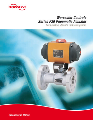
Tightening torques for screws andlocknutsThe actuators must be screwed onto the console with thecorrect torque in order to remain stable during operation.Please use as long screws as possible without the threadsgrounding. ”L” is the screw length according to fig. 6.Fig. 6Tightening torques in Nm:Fixing screw against console:L 16, Mv 125 NmL 18, Mv 140 NmL 20, Mv 155 NmL 22 (max), Mv 170 Nm(the information also applies for screwswhen mounting a console on the upperside of the actuator)End plate screw: 76 NmLock nut for adjustment screw, DA and SR:120 Nm.Drawing 55594AFunction and calibration of the RC88Manual Override1. The Actuator works pneumatically when the handle (A)is in its lower, normal position. The wheel is freely rotating in both directions.Adjustment screws and lockingscrews for the end positions of theActuator (C) (4x)Calibration of the Manual Override, Actuator and GearBox, mounted on valve:Handle for engagingand disengaging theGear Box (A)Adjustment screws andlocking screws for the endpositions of the Gear Box (B)Fig. 7Drawing 007604www.remotecontrol.seRemote Control SwedenBox 80Kontrollvägen 15SE-791 22 FalunSwedenTel 46 (0)23 587 00Fax 46 (0)23 587 45www.remotecontrol.seinfo @ remotecontrol.seRemote ControlGutenbergstr. 22DE-41564 Kaarst-BüttgenGermanyTel 49 (0)2131 795 760Fax 49 (0)2131 795 76115www.remotecontrol.deinfo @ remotecontrol.deRemote Control LtdUnit 40, Trent Valley WorksStation Road, RugeleyStaffordshire WS15 3HBEnglandTel 44 (0)1889 576 888Fax 44 (0)1889 577 676www.remotecontrol.co.ukinfo@ remotecontrol.co.uk-6-Ref No 706B / Art nr 9807062. Unscrew the adjustment screws (B) on the gear box.Then pressurize the Actuator in the left port. Inorder to make it easier when handling the adjustmentscrews, lower the air pressure to 50 % of the nominalvalue once the end position is reached. The adjustmentscrews (C) of the Actuator are then set to the preferredposition. All four of the screws must be applied. Tightenthe locking nuts.3. Pressurize the Actuator and tighten the adjustmentscrews (B) on the Gear Box until they are in contact withthe cog segment at each end position. After the calibration the locking nuts are locked in place.4. Apply the Manual Override to the de-pressurized Actuator by slowly turning the wheel and bringing the handleto the top position. Counter clock-wise to open andclock-wise turning to close. Check the calibration byturning the wheel to both end positions. When everything is correct the Manual Override is disengaged andtransition to normal pneumatic operation is taking place.We reserve the right toalterations without previous notice.Remote Control AsiaNo. 9, Kaki Bukit Road 1#03-03, Eunos TechnolinkSingapore 415938Tel 65 6848 7150Fax 65 6746 5815www.remotecontrol.com.sginfo@ remotecontrol.com.sgRemote Control IncPO Box 355386 Dry Bridge RdNorth Kingstown, RI 02852USATel 1 (0)401 294 1400Fax 1 (0)401 294 3388www.rciactuators.cominfo@ remotecontrol.us
Converting to SR actuators All DA-actuators can be changed into SR actuators by adding spring conversion kits according to the following: 1. Please read the warning above! 2. Dismantle the end plates. 3. Dismantle the pistons. See "Exchange of piston sealings and support element". 4. Mount the pistons according to fig. 4 on page 3. 5.