Transcription
WIRELESS EMERGENCY ALERTSCOMPUTER MODEL AND SIMULATIONRESULTSJuly 2013
TABLE OF CONTENTSSectionPageExecutive Summary . iv1BACKGROUND . 1-12WEA REFERENCE ARCHITECTURE OVERVIEW . 2-13WEA MODELING AND SIMULATION . 3-13.13.23.34Modeling and Simulation Software . 3-1Modeling Constraints . 3-2Modeling Approach . 3-2COMPUTER MODEL ARCHITECTURE . 4-14.1Simulating Network Connections . 4-24.1.1 Wired Connections . 4-24.1.2 IP Cloud Connections . 4-24.1.3 Handset RF Connections . 4-24.2 Simulating Alert Origination . 4-34.3 Simulating Alert Aggregation . 4-34.4 Simulating the Federal Alert Gateway . 4-44.5 Simulating the Combined CMSP Gateway and CBE . 4-44.6 Simulating the CBC. 4-54.7 Simulating a GSM Subnetwork . 4-54.8 Simulating an LTE Subnetwork . 4-64.9 Simulating Cellular Handset Devices . 4-74.10 Output Performance Parameters . 4-85SIMULATION ANALYSIS . 5-15.15.25.35.45.55.66General Assumptions . 5-2Cell Broadcast Network Traffic . 5-3Internet Delays and IPAWS-OPEN Load . 5-5Denial-of-Service Attack. 5-8Transmission Errors . 5-9Active Phone Calls . 5-10DISCUSSION OF RESULTS. 6-1AppendixPageACellular Network Models . A-1BList of Acronyms and Abbreviations . B-1iii
EXECUTIVE SUMMARYThis document describes work undertaken as part of the Wireless Emergency Alerts (WEA)Program, formerly known as Commercial Mobile Alert Service (CMAS), at The Johns HopkinsUniversity Applied Physics Laboratory for the U.S. Department of Homeland Security Science andTechnology Directorate (DHS S&T). A computer model was developed for the purposes ofinvestigating WEA system performance under specific scenarios and to identify recommendedenhancements. This report presents the modeling approach and the results of the simulationsperformed using the model. The results highlight potential improvements that should be consideredby DHS and the Federal Emergency Management Agency (FEMA) in future iterations of WEA.A public alert and warning system like WEA has to be able to operate continuously despitepossible extreme conditions (e.g., massive infrastructure damage, heavy network traffic, cyberattacks). Because it is not possible to generate these conditions for testing in a controlledenvironment, a WEA computer model was developed to simulate the transmission of alert messagesfrom alert origination through delivery to a citizen’s mobile device. This report presents an analysisof simulated system performance under a variety of conditions, including scenarios with extremeconditions.The WEA computer model was built using a discrete event simulation software package. Themodel employs a “black-box” approach because detailed design information about WEA systemcomponents was not available to the project team. With this approach, the model describes only theexternal behavior of the WEA components without detailed information about their specific internaldesign. The model employs numerous configurable equipment attributes, which can be tuned toreflect specific knowledge of these elements should additional design or performance informationbecome available in the future. The model uses alert delivery latency as the main performancemetric. In WEA, different handsets will in general receive an alert at different times. This variabilityis caused by several factors such as different service providers, different locations, interference andtransmission errors, handset state, and so forth. The study described in this document simulated theeffects of various delay factors on alert delivery latency.The main finding of the study is that under normal operating conditions, WEA can alert thepublic with latencies under 5 seconds. A five-second latency is expected to be adequate for manytypes of alerts and warnings. On the other hand, WEA latency can exceed 20 seconds under certainextreme conditions, such as high levels of Internet delay that can be encountered during a majordisaster, or high levels of cell broadcast traffic. The WEA alert delivery success rate is also stronglydependent on phone call volume because alerts are not received by mobile handsets during activephone calls. High levels of phone call volume can cause a significant portion of the target populationto receive an alert delayed by several tens of minutes. Finally, target populations that have poorcellular reception may also have alerts delayed for several tens of minutes.iv
The project team evaluated numerous disaster scenarios as simulation scenarios. Arepresentative subset of the scenarios was selected to study the potential effect of each major delayfactor. The first scenario employed a series of weather alerts to investigate WEA performance as afunction of background (non-alert) cell broadcast traffic load. WEA shares the same channel withother cell broadcast traffic. Therefore, alerts can potentially be delayed if a Commercial MobileService Provider (CMSP) sends substantial commercial broadcast to its subscribers. The simulationresults revealed that WEA latency can exceed 20 seconds when the cell broadcast load is greaterthan 80%. Therefore, the study recommends that CMSPs planning to offer commercial cell broadcastservices to their customers should assign a higher priority level to WEA alerts to reduce this latency.The second and third scenarios, a chemical attack and a major earthquake, respectively, wereemployed to analyze the impact of extremely high levels of Internet delays (e.g., 1 second) and publicalert traffic load on WEA performance. The simulation results revealed that WEA latency againexceeded 20 seconds under such extreme conditions. Most of the latency was due to the protocoloverhead associated with a Hypertext Transfer Protocol Secure setup. The study recommends thatAlert Originators (AO) who are expected to generate alerts with high delay sensitivity, such asearthquake and tornado warnings, use dedicated secure channels to reduce this latency. It alsorecommends the use of Internet Service Providers that offer Service-Level Agreements (SLAs) withguaranteed minimum bandwidth and maximum delay to reduce delays during extreme conditions.Services with such SLAs are typically more expensive, but can maintain a baseline service qualitydespite high network traffic.The fourth scenario analyzed the impact of a denial-of-service attack on the alert Aggregatorduring a series of weather alerts. The findings reveal the need for strong defenses against this typeof attack. The study recommends a distributed architecture for future enhancements to WEA. Theexisting centralized architecture would be unable to operate if the data centers were disabled by acyber attack or other means.The fifth scenario was a nuclear detonation. The study analyzed the impact of very high levelsof transmission errors that can result from electromagnetic noise in order to gauge the delays inWEA messages caused by such transmission errors. WEA relies on multiple repeat transmissions ofalerts to reach handsets that do not receive an alert during the first transmission. A variety ofcauses can increase the need for retransmission, including poor reception and active phone calls.Simulation results indicated that if 10% of the handsets cannot receive an alert due to transmissionerrors, three or more transmissions may be needed to alert at least 90% of a target population.Lastly, the sixth scenario was another series of weather alerts, this time to analyze the impactof high levels of phone call volume. Similar to the fifth scenario, simulation results revealed thatwhen there was heavy phone call volume (exceeding 50% load), four or more transmissions wereneeded to alert at least 90% of the target population.The results in the fifth and sixth scenarios demonstrate the need for optimizing the alerttransmission period. It must be tuned for the expected level of transmission errors and the expectedphone call volume in an area. Selecting a large transmission period increases alert delivery latencyfor some portion of the target population; selecting a small transmission period consumes morenetwork resources. Also, a small transmission period may lead to complaints and opt-outs by anover-alerted public.The results presented in this document can affect a number of important technical,programmatic, and policy decisions that must be made or endorsed by the Federal Communicationsv
Commission, FEMA, DHS, CMSPs, the AO community, and state and local first responders. WEAservice is most critical in the very same circumstances when it is most susceptible to unacceptabledegradations of service. The evolution of the WEA system must be coordinated in light of theconsequences—for the public, for first responders, and for federal disaster response—of thedegradation of service predicted by the WEA simulation results. AOs need to be aware of the worstcase consequences of alert initiation under extreme circumstances.vi
Section 1BACKGROUNDThe Department of Homeland Security (DHS) is committed to using cutting-edge technologiesand scientific talent in its quest to make America safer. The DHS Science and TechnologyDirectorate (S&T) is tasked with researching and organizing the scientific, engineering, andtechnological resources of the United States and leveraging these existing resources into tools to helpprotect the homeland.The Wireless Emergency Alerts (WEA) Program was established by the FederalCommunications Commission (FCC) in response to the Warning, Alert, and Response Act of 2006 toallow wireless service providers to send geographically targeted emergency alerts to theirsubscribers. Under Executive Order 13407, the Secretary of the DHS, in coordination with theDepartment of Commerce and the FCC, is responsible for implementing and administering thenational public emergency alert system and ensuring that the President can alert and warn theAmerican people in the case of an emergency. Within DHS, the Federal Emergency ManagementAgency (FEMA) is responsible for the implementation and administration of the Integrated PublicAlert and Warnings System (IPAWS). FEMA has established the IPAWS program office to, in criticalpart, develop and manage technologies and processes capable of accepting and aggregating alertsfrom the President, the National Weather Service, and state and local emergency operations centers(EOCs), as well as delivering validated, geographically targeted emergency alerts and warningsthrough WEA.The Johns Hopkins University Applied Physics Laboratory (JHU/APL) has been engaged bythe DHS S&T First Responders Group to develop a computer model to simulate WEA andinvestigate system performance under specific scenarios. The results highlight potentialimprovements that should be considered by DHS and FEMA in future iterations of WEA.1-1
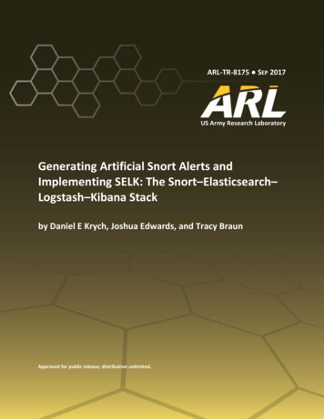
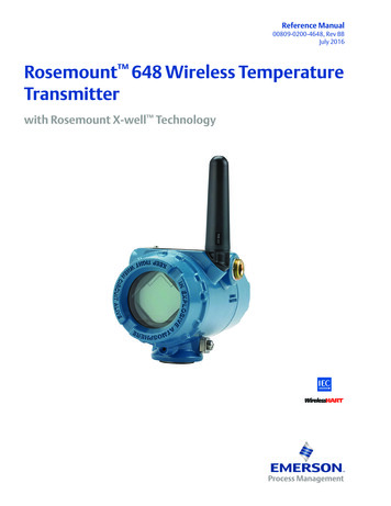
Section 2WEA REFERENCE ARCHITECTURE OVERVIEWIn December 2006, the FCC established the Commercial Mobile Service Alert AdvisoryCommittee (CMSAAC) to recommend system-critical protocols and capabilities for WEA. TheCMSAAC consisted of representatives from state and local governments, Federally recognizedNative American tribes, representatives of the communications industry (including wireless serviceproviders and broadcasters, vendors, and manufacturers), and national organizations representingpeople with special needs.1 In its recommendations, CMSAAC proposed the architecture for the WEAas shown in Figure 2-1.2 The Alert Aggregator and Alert Gateway functionality shown in the figureis currently implemented as part of FEMA’s IPAWS Open Platform for Emergency Networks(OPEN).Figure 2-1 WEA Reference ArchitectureAt a high level, the following actions take place under this reference model:The full list of CMSAAC members is found in “Notice of Appointment of Members to the Commercial MobileService Alert Advisory Committee; Agenda for 12 December 2006 Meeting”, Public Notice, 21FCC Rcd 14175(PSHSB 2006).2 “Commercial Mobile Alert Service Architecture and Requirements,” 12 October 2007.12-1
a. Alert Origination Systems (AOS) at the local, state, and Federal levels generate emergencyalert messages for WEA using a data standard called the Common Alerting Protocol(CAP). These messages are transmitted to the Alert Aggregator via Interface A.b. The Alert Aggregator receives, authenticates, and aggregates emergency alerts from theAOS’s and forwards them to the Federal Alert Gateway.c.The Federal Alert Gateway generates a Commercial Mobile Alert Message (CMAM).d. Based on Commercial Mobile Service Provider (CMSP) profiles maintained in the FederalAlert Gateway, the Federal Alert Gateway delivers the CMAM over Interface C toGateways maintained by the appropriate CMSPs.e.The CMSP Gateway is responsible for formulating the alert in a manner consistent withthe individual CMSP’s available delivery technologies, and handling congestion within theCMSP infrastructure. WEA messages are mapped to an associated set of cell sitetransceivers and transmitted using Cell Broadcast Service (CBS) over the air interfaces.f.Lastly, the alert is received on a customer’s mobile device. The major functions of themobile device are to authenticate interactions with the CMSP infrastructure, monitor forWEA alerts, maintain customer options (such as the subscriber’s opt-out selections), andactivate the associated visual, audio, and mechanical (e.g., vibration) indicators that thesubscriber has chosen as alert options.The WEA Reference Architecture forms the basis of the computer model architectureexplained in Section 4.2-2
Section 3WEA MODELING AND SIMULATIONA public alert and warning system such as WEA must be able to operate continuously evenunder extreme conditions (e.g., massive infrastructure damage, heavy network traffic, cyber attacks).Because it is not possible to generate these conditions for testing in a controlled environment, a WEAcomputer model was developed. This model can simulate the transmission of alert messages fromAOS’s through delivery to a customer’s mobile device and estimate system performance when avariety of conditions are assumed. This includes scenarios with extreme conditions.There are several factors that can delay or prevent sending alerts to a portion of the targetpopulation.3 These factors include the availability of communication paths between WEAcomponents, transmission delays across various interfaces, and message processing and queuingdelays at WEA components. Availability of the WEA service at a given location is also an importantfactor; a handset cannot receive an alert if it is outside of the provider coverage area or WEA servicearea, if some infrastructure damage or system failure prevents WEA service at that location, or if thehandset is simply inside a poor reception area. Radio frequency (RF) interference can causetransmission errors in over-the-air broadcast and prevent reception of the alerts. Finally, handsetstatus (e.g., on/off, active call) will also affect whether a WEA broadcast can be received by ahandset. The WEA computer model was designed with capabilities to simulate the effects of thesefactors and is explained in detail in Section 4.3.1MODELING AND SIMULATION SOFTWAREThe project team evaluated several commercial modeling and simulation (M&S) tools suitablefor WEA model development. Based on evaluation criteria such as available features, ease ofdevelopment, ease of use, customer support, and cost, OPNET Modeler was selected to design anddevelop the WEA computer model. It includes built-in models for networking devices such as routersand switches, network protocols, wired and wireless communication links, servers, and networkclouds. It also allows for the development of custom models and customization of the built-in OPNETmodels. Built-in models and customization features of OPNET Modeler were used to simulate alertorigination, aggregation, Federal and CMSP Gateways, CMSP CBS infrastructure, handsets, andtheir connectivity.OPNET Modeler is a discrete event simulator that simulates the transmission of everynetwork packet from its source to its destination. This allows for highly accurate simulations of realsystems, but requires a lot of processing cycles and memory utilization for large and complexnetworked systems. The tool supports different levels of abstraction at the expense of simulationaccuracy as a workaround for modeling such complex systems.3In this document the term “target population” refers to the intended recipients of a public alert or warning.3-1
3.2MODELING CONSTRAINTSA number of constraints shaped the development of M&S capabilities for WEA. First, the verylarge number of cell towers and cellular devices that can potentially receive an alert makes itimpractical to run simulations at full accuracy. Certain simplifications were used to develop feasiblesimulations, such as more abstract models of cellular transmission and scaling down the number ofcell towers and cellular devices.Limited information was available about the internal architecture and performance attributesof the AOS’s, IPAWS-OPEN, and CMSP network components. For example, IPAWS-OPEN usesAkamai services over Interface A for load balancing and failover switching between two data centers.However, detailed information about these services is sensitive and subsequently restricted.Validation of the WEA computer model requires WEA performance data, such as processingand transmission delays, network capacity, and cell broadcast reception statistics, obtained bysystem testing or field measurements. However, the only performance data available to JHU/APL atthe time of this study were the results of an IPAWS-OPEN performance test.4 The test consisted ofposting 1000 alert messages to IPAWS-OPEN and retrieving messages from the system while thealerts were being posted. This operation took 17 minutes to complete. These data were used toconfigure the alert processing capacity of the IPAWS Aggregator model. Other components of thecomputer model were configured using other sources of information, including relevant systemperformance requirements.Generic models of Universal Mobile Telecommunications System (UMTS) and Long-TermEvolution (LTE) technologies were available in OPNET Modeler and some other commercialsoftware tools, but research uncovered no available commercial or open-source models for CBSdelivery over Global System for Mobile Communications (GSM), UMTS, or LTE. Furthermore,existing equipment models generally supported simulating equipment failure, but very few modelssupported realistic recovery behavior.Lastly, timelines are required for simulation scenarios, but there is no body of agreed-uponemergency alerting timelines for incidents where WEA might be involved.3.3MODELING APPROACHGiven the absence of detailed information about IPAWS-OPEN elements and internal CMSPequipment, the decision was made to use the standard OPNET Modeler network, server, andprotocol models. WEA- and CBS-specific extensions were added to these standard models, and theywere used to represent alert origination, aggregation, Federal and CMSP Gateways, Cell BroadcastEntity (CBE), and Cell Broadcast Controller (CBC) functions, and their connectivity including theAkamai services. These models have been used successfully by many network analysts to representgeneral processing and network routing in situations where specific data are lacking. They areconfigurable by setting equipment attributes so that they can reflect specific knowledge of theseelements, should these data become available in the future. Without specific design data, the WEAcomponents were modeled using a “black-box” approach which does not include detailed modeling of4“FEMA IPAWS-OPEN Active-Active Release 3.02 Quality Assurance Independent Validation and VerificationPerformance Test and Evaluation Report,” Version 1.0, 29 August 2012.3-2
their internal dynamics. This approach captured the external behavior of WEA components in themodel, without internal details.It is not feasible to simulate tens of thousands of cellular devices directly in OPNET Modeleror any other discrete event simulator. For this reason, the numbers of cell towers and cellulardevices have to be scaled down during the simulation runs. In this case the results should beextrapolated to reflect the actual system performance.The simulation of each scenario requires a schedule of WEA alerts relevant for that scenario todrive the model. Furthermore, each scenario may contain various external events that could beexamined as part of the model. Therefore, events such as changes in equipment characteristics (e.g.,being non-operational) or network characteristics (e.g., delays across Interface A or Interface C) arealso inputs to a simulation analysis. To make the simulation configuration easy for the analyst tocreate and easy for the alert community of interest to review, all these events were expressed in asimple text scenario file ingested by the model.The ability to examine the effects of equipment outages is a key element in the assessment ofthe effectiveness of WEA in response to certain types of events. This was accomplished by disablingthe nodes and links that represent the failed equipment in OPNET Modeler. When re-enabled, mostof these equipment models continue from the internal state they were in before being disabled. Theydo not support a more realistic recovery that represents the behavior of equipment in the process ofcoming back online. This was not a significant issue for the simulation scenarios selected in thisstudy because the scenarios had durations that were too short to see any recovery after failure. Forthis reason, the disable feature was used without any need for creating custom code for recovery.After an initial examination of the cellular system models available with OPNET Modeler, itwas decided to customize two of them with the addition of CBS modeling:a. A basic GSM model formerly developed for the Department of Defense (DoD)b. The built-in LTE model in OPNET ModelerThe models of these two cellular systems were different enough that rather than trying to create acommon capability used in both, a distinct, custom CBS model was made for each one.OPNET Modeler also has a built-in UMTS network model. Adding CBS support to this modelwas considered as an option in the early stages of WEA model design, but because cell broadcast overUMTS networks is expected to show similar performance to cell broadcast over GSM networks, itwas decided that the GSM and LTE models would be sufficient for the purpose of this work. If thereis specific need to simulate UMTS cell broadcast, this can be accomplished by using a genericwireless broadcast model based on the built-in Worldwide Interoperability for Microwave Accessmodel with radio characteristics made similar to UMTS. Future addition of CBS support to the builtin UMTS model is also possible, if desired.Table 3-1 lists all WEA functional components and networks that have been modeled.Communication link models and models used for simulation configuration are not listed. The tablealso shows the base model used for each WEA component and added functionality to the base modelto simulate the WEA system. A detailed description of each model is provided in Section 4.3-3
Table 3-1 List of WEA ModelsModeled FunctionalComponentBase ModelModificationAlert OriginationAOSBuilt-in workstation modelAdded AOS functionalityIPAWS-OPENAlert AggregatorBuilt-in server modelAdded alert AggregatorfunctionalityFederal Alert GatewayBuilt-in server modelAdded Federal Alert GatewayfunctionalityNetworksInternetBuilt-in Internet Protocol(IP) cloud modelNoneCMSP Backbone NetworkBuilt-in IP cloud modelNoneCMSP (all)CMSP Gateway and CBEBuilt-in Gateway modelAdded CMSP Gateway and CBEfunctionalityCBCBuilt-in Ethernet servermodelAdded CBC functionalityCMSP (GSM)Base Station Controller (BSC)DoD GSM modelAdded CBS functionalityBase Transceiver Station (BTS)DoD GSM modelAdded CBS functionalityMobile Station (MS)DoD GSM modelAdded CBS functionalityCMSP (LTE)Evolved Packet Core (EPC)Built-in LTE modelNoneEnhanced Node B (eNodeB)Built-in LTE modelAdded CBS functionalityUser Equipment (UE)Built-in LTE modelAdded CBS functionality3-4
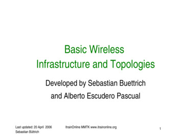
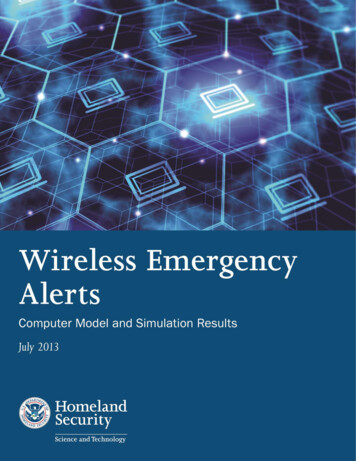
Section 4COMPUTER MODEL ARCHITECTUREThe WEA computer model uses the same architecture as the WEA network architecture.Figure 4-1 shows representative models for AOS’s (labeled as Emergency Operations Center (EOC)),Aggregator and Federal Alert Gateway functionality at two data centers, connections to multipleCMSP networks, and the Internet.Figure 4-1 WEA Computer Model ArchitectureAlthough only three EOCs and three provider networks are shown in the figure for simplicity,the model supports much larger numbers of instances for each. The Master Node is responsible forthe scenario configuration. It reads a text file that describes all events in a scenario—such as alertgeneration and equipment failure—and orchestrates these events using the appropriate OPNETModeler methods. Each of the three Provider Network nodes in Figure 4-1 is actually a full CMSPinfrastructure, hidden from view for simplicity. Each of these nodes can be a GSM network model or4-1
an LTE network model, based on the scenario being analyzed. These representative elements areexplained in subsequent sections of this document.4.1SIMULATING NETWORK CONNECTIONSThree kinds of connections were modeled for the WEA simulation studies: simple wiredconnections, IP cloud connections, and cell phone RF connections.4.1.1WIRED CONNECTIONSSimple wired connections are used between the Aggregators and Federal Alert Gateways andfor connections within the CMSP domain between the CMSP core network and cell towers. They areassigned a capacity and a level of background (non-WEA) traffic. These connections can model pointto-point communication between two nodes with various transmission effects, such as delay andpacket loss. They can also model logical interfaces between two functional entities without anytransmission delay or loss.4.1.2IP CLOUD CONNECTIONSThe Internet connectivity between AOS’s, IPAWS data centers, and the CMSP networks wasmodeled using a single IP cloud. This model supports associating capacity, delay, and packet losscharacteristics with multiple interfaces. These characteristics can be adjusted to meet specificscenario conditions. The model also supports simulating network congestion caused by highbackground traffic, and has the ability to disable interfaces into the cloud for a period of time. Theconnectivity between AOS’s and IPAWS data centers through the cloud model (Interface A) usesTransport Layer Security (TLS) and Hypertext Transfer Protocol Secure (HTTPS). The connectivitybetween IPAWS data centers and CMSP networks through the cloud model (Interface C) usesInternet Protocol Security (IPSec). The IP backbone inside the CMSP networks was also modeled bya single IP cloud model, but with attributes different from the Internet cloud model.4.1.3HANDSET RF CONNECTIONSThe over-the-air connection between the CMSP network (i.e., cell towers) and the handsets is acritical element of the WEA simulation capability. OPNET Modeler uses a series of code modulescalled pipeline stages to model the transmission and reception of RF signals. Some are associatedwith the radio transmitter in an OPNET model and some are associated with the radio receiver.Each pipeline stage receives certain inputs from the simulation framework and from the previouspipeline stage, and must set values for the next pipeline stage. There are default radio pipelinestages as well as those customized for specialize
This document describes work undertaken as part of the Wireless Emergency Alerts (WEA) Program, formerly known as Commercial Mobile Alert Service (CMAS), at The Johns Hopkins . dependent on phone call volume because alerts are not received by mobile handsets during active phone calls. High levels of phone call volume can cause a significant .