Transcription
Biomedical Research 2015; 26 (4): S29-33ISSN 0970-938Xwww.biomedres.infoFinite Element Analysis in Additive Manufactured Customised BoneScaffoldRashia Begum S a*, Arumaikkannu GbaDepartment of Mechanical Engineering , bDepartment of Manufacturing Engineering, College of Engineering Guindy,Anna University, Chennai, Indiae-mail:, arumai@annauniv.edu*Corresponding Author. Tel: 91 9444786046, E-mail: rashia ibrahim@yahoo.comAbstractBio Additive Manufacturing (BAM), an interdisciplinary field of Additive Manufacturing (AM)and Tissue Engineering (TE), aims to manufacture the customised bone scaffold for bone replacement. One of the current challenges in bone tissue engineering is to create customised scaffolds with suitable mechanical properties, high porosity, full interconnectivity and suitable poresize. In this paper, the patient’s CT scan data in DICOM format is exported into MIMICS software to convert the 2D images into 3D IGES data. The customised bone scaffolds with pore sizeof 0.8mm and inter pore distance ranging from 0.6 mm to 1 mm are developed in modeling software and porosities of customised bone scaffolds are determined. The customised bone porousscaffold and ASTM standard compressive specimens were fabricated through AM technique. Finite element analysis (FEA) was carried out to study the mechanical properties oKeywords: Additive Manufacturing, Bone Scaffold, Pore size, Finite Element Analysis , Tissue Engineering, PorosityAccepted July 27 2015IntroductionAdditive Manufacturing processes produce end-usecomponents from CAD models by additive materiallayer by layer, and the final components are often produced in a single step without the requirement for anyadditional processing. [1].Earlier Additive Manufacturing techniques were used for “Rapid Prototyping” in thedomain of product design and development for conceptmodelling, pattern building, assembly verification andfunctional testing. In the recent times, Additive Manufacturing techniques are being used for the productionof actual end-use products for various sectors. One ofthe interesting sector with significant potential impact isthe medical field, where implants, scaffolds and prosthesis are being manufactured using Additive Manufacturing Technique[2]. Traditional methods of scaffoldfabrication include fiber bonding, solvent casting andparticulate leaching [3], membrane lamination, gasfoaming, cryogenic induced phase separation [4,5] andso on. However, all of these techniques are mainlybased on manual work and lack of corresponding designing process, so extra procedure was needed to obtain suitable shape and the microstructure. These traditional techniques also have many disadvantages such aslong fabrication periods, poor repeatability and insufficient connectivity ofpores[6]. To overcome the limitations of these conventional techniques, automated computer controlled fabrication techniques, such as Additive Manufacturing(AM), are being explored.Many of the researchers [7,8] present the patient specific implant fabrication and its property evaluation. Thispaper presents the fabrication of the customised boneporous scaffold and its compressive property evaluationusing FEM.In this paper, Patient data derived from CT (Computerised Tomography) scan was used in Materialise MIMICS (Materialise Interactive Medical Image ControlSystem) software to convert two dimensional data inDICOM (Digital Imaging and Communications in Medicine) format into three dimensional data in IGES (Interactive Graphic Exchange Specification) format. Thecustomised bone porous scaffold with pore size of 0.8mm diameter and inter pore distance ranging from 0.6mm to 1 mm in steps of 0.1 mm were created usingDassault Systems SOLIDWORKS 2011 modeling soft-Biomed Res- India 2015 Volume 26 Issue 4Special section: Applications of Rapid Prototyping Techniques in Bio-Materials –ARTBM201529
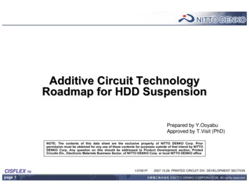
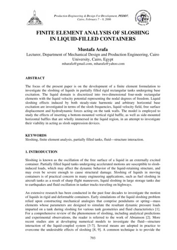
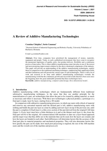
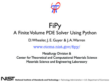
Begum/Arumaikkannuware. The customised bone porous scaffold and ASTMstandard compressive specimens were fabricatedthrough SLS technique. Finite element analysis (FEA)was carried out to study the mechanical properties of thepolyamide scaffolds.Materials and MethodsModeling of customised bone porous structuresThe patient’s DICOM images from Computed Tomography (CT) scan are used in Materialise InteractiveMedical Image Control System (MIMICS) software toget three dimensional details of the bone. The medCAD module in MIMICS is used to export the 3D model data from the imaging system to the CAD system inIGES file format. This IGES format is imported intoDassault Systems SOLIDWORKS 2011 software togenerate the solid model. The total length of the tibiabone was 376 mm. Fig.1 shows the region selected forstudy and considered as defective bone.During the SLS process, a powder bed is formed in thebuild chamber and a laser scans across the powder bedin a series of lines parallel to the x-axis , moving slightly in the y direction after each line. As it scans, the laserliquefies and fuses powder material in a selected regionof the part chamber determined by a cross –section in a3D CAD model of the part being produced. After eachcross-section is finished, a layer of powder is spreadover the newly sintered layer, and the sintering processbegins again. In this way, the part is built up layer bylayer. After SLS processing was completed, the scaffolds were allowed to cool inside the machine processchamber and were then removed from the part bed. After the scaffolds were fabricated, loose powder was removed from the pores via sandblasting. The five customized. bone porous scaffolds were fabricated using3Dfast Srl on a Formiga P100 system (EOS GmbH) inpolyamide EOSINT P/PA2200.Compression TestThe compressive cubic test specimens conforming to theASTM D695: ISO 604. The five compressive cubic testspecimens with size 25.4 mm x 25.4 mm x 25.4 mmwere fabricated using 3Dfast Srl on a Formiga P100system (EOS GmbH) in polyamide EOSINT P/PA2200as shown in Fig. 2.Figure 1.Region considered as defective boneThis region has been taken at a distance of 164 mm fromthe knee. The height of this region was taken as 5 mm andmodeled as 4 layers each of 1.25 mm thickness. In the present work, five customised bone porous scaffolds with poresize of 0.8 mm diameter [9] and inter pore distance rangingfrom 0.6 mm to 1 mm in steps of 0.1 mm were createdusing Dassault Systems SOLIDWORKS 2011 software.Table 1 presents the 3D CAD model developed for the fivecustomised bone scaffolds.FabricationFigure. 2 SLS processed Polyamide compressive specimens with inter pore distance 0.6, 0.7, 0.8, 0.9,1 mmrespectively.Compressive specimens were mechanically tested usinga TINNUS OLESAN Universal Testing Machine. Thespecimen was placed between compressive steel platesparallel to the surface. The specimen was then compressed to 50 % strain between the two steel plates at arate of 1 mm/minFE model and load conditionsThe compressive specimen was made of PolyamideSLS is a laser-based solid free form technique in whichPA2200 material, simulated as a linear, elastic and isoan object is built layer–by-layer using powdered materitropic material. For compressive analysis, all the nodesals, radiant heaters, and a computer controlled laserat the bottom surface were arrested, and compressive[10].The CAD data for the customised bone porousload of 2000 N was applied at the top surface as thescaffolds were exported from Dassault Systemspressureload in the Z - direction. Finite element analySOLIDWORKS software in .stl (stereolithography) filesiswascarriedout on five compressive specimens informat and processed via the SLS application software.ANSYS 13 software.Biomed Res- India 2015 Volume 26 Issue 430Special section: Applications of Rapid Prototyping Techniques in Bio-Materials –ARTBM2015
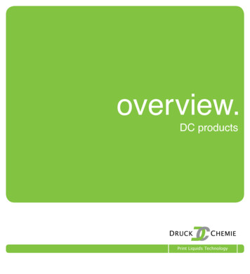
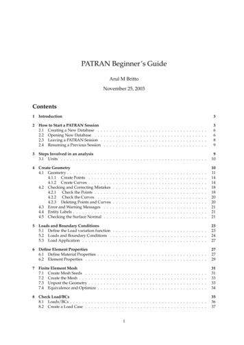
Finite Element Analysis in Additive Manufactured Customised Bone ScaffoldResults and DiscussionCustomised bone porous scaffold fabricationThe customised bone porous scaffolds made of polyamide PA2200 with pore size of 0.8 mm diameter and inter pore distance ranging from 0.6 mm to 1 mm in stepsof 0.1 mm were fabricated by using Selective Laser Sintering Technique. All the fabricated customised boneporous scaffolds possessed well defined pores (illustrated in Fig. 3.a.) and its structural configuration was alsoobserved to be consistent with the CAD data. (illustratedin Fig.3.b.)particulates, rather than the pore size distribution andinterconnectivity in high volume fraction void open-cellfoams [11]. In the present work, the pore size distributionin the porous structure could be easily controlled andmeasured as the customised bone porous structures wasmodeled using computer aided solid modeling package.Figure 3b. Scaffold CAD modelThe porosity was calculated using the formula given inEquation 1Figure 3a. Fabricated scaffold ( Pore size 0.8 mm, inter pore distance 1 mm)Determination of porosityThe conventional technique used to measure the porosityis mercury intrusion porosimetry, which is bettersuited for characterising the average channel size between (1-) x100(1)WhereV1 Volume of porous scaffold with pores mm3.V2 Volume of porous scaffold without pores mm3.Φ Porosity in %Table 1. 3D CAD model of customised bone scaffoldPore size(mm)0.80.60.70.80.91Using the equation 1, the theoretical porosities weredetermined based upon the volumes computed from thethe volumes of customised polyamide scaffold withsolid model package and provided in Table 2. The popores (V1) and the volumes of customised polyamidescaffold without pores (V2) were determined. Using therosity was also determined experimentally by determinequation 1, the experimental porosities were determineding the mass of the fabricated customised polyamidefor the five customised bone porous structures underscaffold with pores and the customised polyamide scafstudy. The relationship between experimental and theofold without pores. Knowing the density of polyamide,Biomed Res- India 2015 Volume 26 Issue 431Special section: Applications of Rapid Prototyping Techniques in Bio-Materials –ARTBM2015
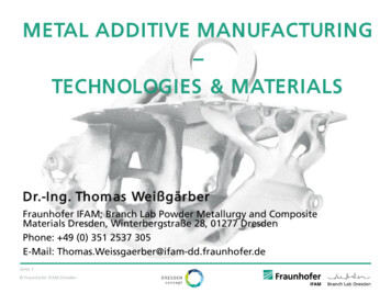
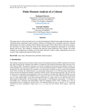
Begum/Arumaikkannuretical porosity is shown in Figure3.strength for the polyamide specimens are shown in Table 2.Figure. 3. Relationship between Experimental Porosityand Theoretical PorosityThe level of porosity, pore size distribution, pore morphology and the degree of pore interconnectivity inbone grafts significantly influence the extent of boneingrowth [12]. The average experimental porosity of thecustomised bone porous structures is 27.3 % against thetheoretical porosity of 31.8 %, showing the reduction of14 % compared to theoretical porosity. This can be attributed to the limitations of the Additive ManufacturingProcess employed where clogging of pores leads in increase in volume of customised bone porous structuresand decrease in experimental porosity.Figure. 4. Stress strain curve for the compressive cubictest specimensTable 2. Details of Compressive stiffness and compressive strengthS.No Inter poreCompressiveCompressivedistance(mm) Stiffness (MPa) Strength (MPa)10.658.595.7620.71087.25Mechanical Properties of Polyamide samplesIn tissue engineering applications, porous implants musthave sufficient mechanical strength to retain their initialstructures after implantation, particularly in the reconstruction of hard, load – bearing tissues, such as bonesand cartilages. The bio stability of many implants depends on factors such as strength, elasticity, absorptionat the material interface and chemical degradation.Therefore, the investigation of compressive properties isof primary importance in determining the suitability ofthe designed porous scaffold.In this study, the response of ASTM standard cubic testspecimens under compression loading was determined.The stress – strain relations obtained from the compressive cubic test specimens are shown in Fig. 4.Three definite regions could be observed from the stressstrain curve for all the five samples namely, a linearelastic region, a region where rate of increase of stresswith strain reduces steadily and a region where thestress increases steeply. The deformation of the cubicpolyamide sample was elastic and, hence, recoverable,while those in the subsequent two regions were nonrecoverable. The compressive stiffness and compressive30.81114.6340.91085.915192.165.66Finite Element Analysis of Compression Testing SamplesFinite Element Analysis was carried out using ANSYS13 software, to compare the stress fields developed underuniaxial compression. It was found from the compressiontesting that the behaviour of the material is linear at 2000N. In finite element simulation the same compressiveload was applied, and the finite element analysis was carried out using ANSYS 13, for the five compression testing samples. The details of the experimental stress andnumerical stress are presented in Table 3. Further, it maybe noted that the experimental results of polyamide cubicspecimens closely matches with the numerical resultswith a maximum variation of 11 %.S.No12345Table 3. Details of Compressive stressInter poreExperimental NumericalDistanceCompressiveCompressive(mm)Stress (MPa)Stress 6Biomed Res- India 2015 Volume 26 Issue 4Special section: Applications of Rapid Prototyping Techniques in Bio-Materials –ARTBM201532
Finite Element Analysis in Additive Manufactured Customised Bone ScaffoldConclusionThe customised bone porous scaffolds made of polyamide with pore size of 0.8 mm diameter and inter poredistance ranging from 0.6 mm to 1 mm in steps of 0.1mm were designed and fabricated using Additive Manufacturing Techniques and differences in porositieswere evaluated. The use of this Additive Manufacturingtechniques promises new cost-effective and rapid solutions to customized made– to–order bone porous scaffold production. Mechanical properties of porous polyamide samples were determined. Finite element analysisof polyamide specimen was completed and therebycompared the properties with the properties of humanbone. Thus SLS process has been able to produce thecustomised bone porous polyamide scaffold with properties similar to human trabecular bone and maxillofacial cancellous bone.Reference1.2.3.4.5.6.7.8.9.Franco A., et al.” Experimental analysis of selectivelaser sintering of polyamide powders: an energy perspective”, Journal of cleaner production 2010;18(1): 1722–1730.Goodridge RD, Tuck CJ., Hague RJM. “Laser sintering of polyamides and other polymers”, Progressin Materials Science 2012; 57(1): 229-267.Linbo,W., Jiandong, D. “Compression Molding ofPorous Scaffolds with complicated shape for TissueEngineering”, Polymer Material Science and Engineering 2005; 25 (1): 296–299.Deville, S., Saiz, E.,Tomsia, A.P., “Freeze casting ofhydroxyapatite scaffolds for bone tissue Engineering”, Biomaterials 2006; 27(1): 5480–89.Madihally, S.V., Howard, W.T. “Porous chitosanScaffolds for tissue engineering”,Biomaterials1999; 20(1):1133–1142.Junmin, Q., Kai.C.,Hao A., Zhihao, J. “Progress inresearch of preparation technologies of porous ceramics”, Ordnance Material Science and Engineering 2005; 28(5): 60-64.Cruz, F., Coole, T., “Fabrication of bioceramic/biopolymer bone implants using selectice lasersintering”, International Journal of Computer Applications in Technology 2009; 36(1): 16–24.Harrysson,O., Cormier,D., “Direct fabrication ofcustom orthopedic implants using electron beammelting technology” Advanced manufacturing technology for medical applications 2006; 191-206.Chu, T.M.G., Hollister, S.J., Feinberg, S.E. “Hydroxyapatite implants with design internal Architecture”, Journal of Materials science Materials inMedicine 2001; 12(1): 471-78.10.11.12.13.14.15.Deckard et al, “Selective Laser Sintering. Mechanical Engineering. Austin” 1998; University of Texasat Austin.Atwood, R.C. et al., “Analysis of pore interconnectivity in bioactive glassfoams using X-ray 9 -1033.Tancred, D.C., et al., “ A synthetic bone implantmacroscopically identical to cancellous bone”, Biomaterials 1998;19(1): 2303- 2311.Goldstein, S.A., et al “The mechanical properties oftrabecular bone: Dependance on anatomic locationand function”, J Biomech 1987; 20(11):1055- 1061.Sudarmaji,N., Tan,J.Y., Leong,K.F., Chua,C.K.,Loh,Y.T. “Investigation of the mechanical properties and porosity relationships in selective lasersintered polyhedral for functionally graded scaffolds”, J.Acta Biomaterialia 2011; 7(1): 530-537.Misch,C.E.,Qu,Z., Bidez,M.W. “Mechanical properties of trabecular bone in the human mandible:implications for dental implant treatment planningand surgical placement” ,J.Oral Maxillofac.Surg.1999; 57(1): 700-706.Correspondence to:S. Rashia BegumAsst. Professor (Sr.Gr)Department of Mechanical EngineeringCollege of Engineering Guindy, Anna UniversityChennai,Tamilnadu, IndiaBiomed Res- India 2015 Volume 26 Issue 4Special section: Applications of Rapid Prototyping Techniques in Bio-Materials –ARTBM201533
Keywords: Additive Manufacturing, Bone Scaffold, Pore size, Finite Element Analysis , Tissue Engineering, Porosity Accepted July 27 2015. Introduction . Additive Manufacturing processes produce enduse - components from CAD models by additive material layer by layer, and the final components are often pro-