Transcription
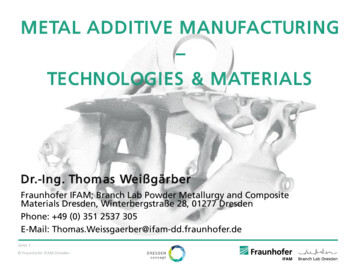
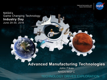
Journal of Research and Innovation for Sustainable Society (JRISS)Volume 3, Issue 1, 2021ISSN: 2668-0416Thoth Publishing HouseDOI: 10.33727/JRISS.2021.1.4:25-32A Review of Additive Manufacturing TechnologiesCosmina Chiujdea1, Sorin Cananau11Doctoral School of Industrial Engineering and Robotics Faculty, University Politehnica ofBucharest, RomaniaE-mail: q.cosmina@yahoo.comAbstract. Over time, companies have prioritized the management of money, materials,equipment and people. Today, in such a globalized environment, they have come to recognizethe paramount importance of quality, price, fast product delivery, flexibility and a continuousprocess of innovation. This is where additive manufacturing comes into play as one of the newestand most promising improvement solution for the above mentioned components of the industry.This paper will provide an understanding of the additive manufacturing technologies, analizethem in comparison to the traditional machining techniques, emphasizing their application fieldsand their limitations and will present the various types of said technologies. There is still a lot ofwork and research to be done until additive manufacturing technologies overtake themanufacturing world but the continuous growth and successful results that have been seen sincethe beggining show the great undeniable potential that these technologies have.Keywords: additive manufacturing, computer-aided design, three-dimentional model.1. IntroductionAdditive manufacturing (AM), technologies which are fundamentally different from traditionalsubstractive manufacturing techniques, in the sense that they use another principle for thematerialization of a part, are technologies that allow the part to be created by adding material, as muchas necessary and where is necessary. With these new technologies a physical product, a prototype or afinal part is made, layer by layer, starting from a 3D model.In comparison with subtractive manufacturing processes, in which one starts with a block of materialand removes any unwanted material until the desired part is left, additive manufacturing starts withnothing and builds the part one layer at a time by adding each new layer on top of the previous one, untilthe part is complete.[1] Each layer is a thin cross-section of the part derived from the original CAD data(figure 1). Every layer must have a finite thickness to it and so the thinner each layer is, the closer thefinal part will be to the original. All commercialized AM machines to date use a layer-based approachand the major ways that they differ are in the materials that can be used, how the layers are created, andhow the layers are bonded to each other. Such differences will determine factors like the accuracy of thefinal part plus its material properties and mechanical properties. They will also determine factors likehow quickly the part can be made, how much post-processing is required, the size of the AM machineused, and the overall cost of the machine and process.[2]25
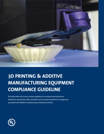
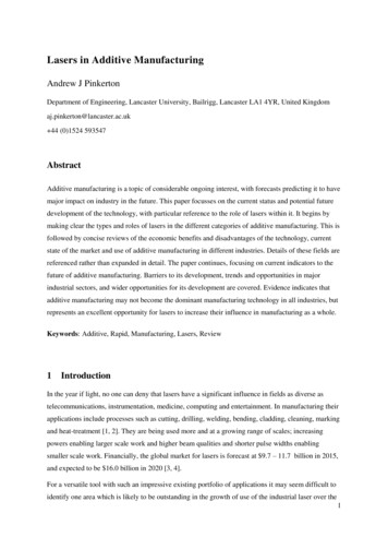
Journal of Research and Innovation for Sustainable Society (JRISS)Volume 3, Issue 1, 2021ISSN: 2668-0416Thoth Publishing HouseFigure 1. Slicing of a part into layers.1.1. The additive manufacturing process chainAM involves a number of steps that move from the virtual CAD model to the physical resultant part.The additive manufacturing process chain is shown in figure 2.Figure 2. The additive manufacturing process chain.The first step in the additive manufacturing process is always the creation of the digital model. Thereis a vast variety of 3D computer aided design (CAD) software that can be used to obtain a fully enclosedvolume. There are other methods to obtain the desired model too, such as reverse engineering ortomography, but these are not as flexible as the first mentioned.The next step is the conversion of the CAD model to an STL file (STereoLithography). STL hasseveral backronyms such as "Standard Triangle Language" and "Standard Tessellation Language". MostCAD system can output an STL file, which is used as the basis of layering the model. STL is a simpleway of describing the shape of the model by approximating the model surface with triangular facets.[4]After an STL file has been generated, the file is imported into a slicer program. This program takes theSTL file and converts it to G code. G code is a numerical control (NC) programming language. It is usedin computer aided manufacturing (CAM) to control automatic machine tools (including CNC machinesand 3D printers). The slicing program allows the designer to customize the construction parameters,including the support, the layer height and the orientation of the part.Once the software has sent the part build instructions to the machine, it starts to build the part layerupon layer. There are several ways to form a cross section, depending on the particular technology beingused. Some AM machines use computer-controlled scan head (laser scanner, nozzle, cutting knife, etc.)to scan lines in order to form a layer cross section (through curing resin, sintering powder, bindingpowder, cutting paper, etc.). The newly formed layer will be bonded to the previous one until the wholepart is finished.[4]After the part is finished being built, it has to be removed from the machine and post-processed. Theremoval requires interaction with the machine, thus safety measures must be taken. Post-processing hasto be done next, with extreme caution, since the parts might be weak at this point, or they still havesupport material in need of removal. Cleaning the part of left-over powder or resin might also berequired, and, in many cases, even further processing such as machining, if a surface requires a finerfinish than the AM machine can provide, infiltration to make the part stronger, heat treatment for metalparts, or colouring and painting if the part needs to be in a colour other than that provided by the AMmaterial.[1]1.2. Current Usage of Additive ManufacturingIn recent years, AM technologies have been increasingly applied in various industry sectors to improvethe material performance and enhance energy efficiency and have been considered as one of the nextgeneration solutions coming with advantages such as cost reduction, speed, accessibility, sustainability,ability to create complex geometries. [5]Wohlers Associates is a company that helps define, coordinate, and review the results of experimentsthat test methods of rapid product development, additive manufacturing, and 3D scanning/imaging.26
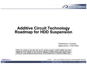
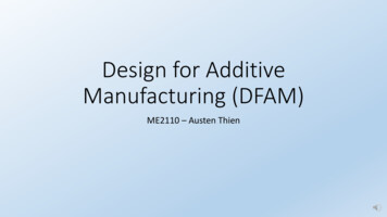
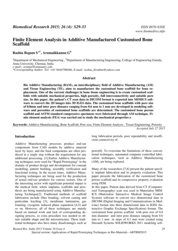
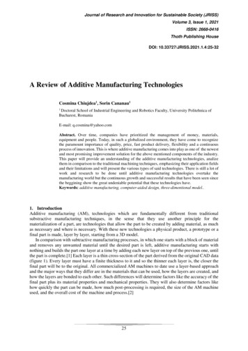
Journal of Research and Innovation for Sustainable Society (JRISS)Volume 3, Issue 1, 2021ISSN: 2668-0416Thoth Publishing HouseAccording to their 2018 annual ‘state of the industry’ report [6] the areas of use for AM are as shown infigure 3.Figure 3. Industries using additive manufacturing, according to the 2018 Wholers Report.Although there are many advantages in choosing these technologies, as they have been scarcelypointed out in this paper thus far, AM also comes with its disadvantages. These include the relativelyhigh cost of the machines and operation, slow production rate, limited materials and the shrinkage offabricated parts.2. Types of additive manufacturing technologiesThere are many additive manufacturing processes available and there has yet to be determined an idealclassification of all of them. What makes it difficult to do so are the their differences in terms ofmaterials, energy sources, types of feedstocks used and conveyance of feedstocks.The struggle is to finda classification that will not exclude any of the processes while also allow room to accommodate newones that have not been discovered yet.[3]Although the classification of AM processes is an ongoing debate, with new process techniquesemerging every day, this present paper will only introduce the categories published by the AmericanSociety for Testing and Materials (ASTM) Committee F42 on Additive Manufacturing Technologies(Standard Terminology for Additive Manufacturing Technologies, 2012), which, broadly, divides thembased on how the material is solidified, as follows: Vat Photopolymerization, Material Jetting, BinderJetting, Material Extrusion, Powder Bed Fusion, Sheet Lamination and Directed Energy Deposition.[7]2.1. Vat PhotopolymerizationVat Polymerisation technologies uses a vat of liquid photopolymer resin, out of which the model isconstructed layer by layer. An ultraviolet (UV) light is used to cure or harden the resin where required,whilst a platform moves the object being made downwards after each new layer is cured. The maintechnologies in this category are stereolithography (SLA) using either lasers or DLPs (Digital LightProcessing), and Continuous Liquid Interface Production (CLIP).[7] Out of these three,Stereolithography is the first version of additive technology invented and is the most widely used AMprocess technique nowadays.As it can be seen in figure 4 the platform starts at one layer’s thickness beneath the surface of thepolymer. The computer uses the sliced model information to control the dynamic mirrors, which directthe laser beam over the vat surface, scanning the cross section of one layer of the part. The platform thendescends into the resin, allowing a fresh thin film to form over the previous one . The laser startsscanning the new layer, building the next slice as well as bonding it to the previous one. The process isrepeated until the desired part is built. The waste-free quality of this process is highlighted by the fact27
Journal of Research and Innovation for Sustainable Society (JRISS)Volume 3, Issue 1, 2021ISSN: 2668-0416Thoth Publishing Housethat the leftover resin can be used for a future builds. For overhanging features of the part, easilyremovable synthetic supports can be designed to ensure the correct formation.[1][4]Figure 4. Schematic representation of the Stereolithography process.2.2. Material JettingMaterial jetting creates objects in a similar manner to an inkjet printer. Material is jetted onto a buildplatform using either a continuous or Drop on Demand (DOD) approach.The printer head moves horizontally above the platform, depositing liquid photopolymer materialonto it for each layer of the model. The material is then cured by UV light or allowed to cool and harden.Machines vary in complexity and in their methods of controlling the deposition of material. The materiallayers are then cured or hardened using ultraviolet light. The process is then repeated until thecompletion of the part. In figure 5 it can be seen that the print-head is designed to deposit both the partmaterial, as well as any required support material that will subsequently need to be removed.As material must be deposited in drops, the number of materials available to use is limited. Polymersand waxes are suitable and commonly used materials, due to their viscous nature and ability to formdrops.[7]Figure 5. Schematic representation of the Material Jetting process.2.3. Binder JettingSimilar to the technologies presented so far, the Binder Jetting process makes use of a descendingplatform, building the product layer by layer. In this case the materials used in the process are a powderbased material that is spread over the build platform using a roller, and a binder, usually liquid, that isdeposited on top of the powder where necessary. The print head moves horizontally depositingalternating layers of the build material and the binding material thus creating the final piece. Figure 6shows the schematic representation of the Binder Jetting process.28
Journal of Research and Innovation for Sustainable Society (JRISS)Volume 3, Issue 1, 2021ISSN: 2668-0416Thoth Publishing HouseIn contrast to the others, this process does not require additional supports as the unbound powderserves this role, being easily removed after completion.Figure 6. Schematic representation of the Binder Jetting process.2.4. Material ExtrusionThe Fuse deposition modelling (FDM) is shown in figure 7. This is one of the most common andaccessible additive manufacturing technologies. Material is being fed to a nozzle, where it is heated andthen deposited in a continuous stream onto the moving platform. Each new layer fuses automatically tothe previous because of its melted state.Figure 7. Schematic representation of the Material Extrusion process.2.5. Powder Bed FusionPowder Bed Fusion technologies includes: Direct metal laser sintering (DMLS), Electron beam melting(EBM), Selective heat sintering (SHS), Selective laser melting (SLM) and Selective laser sintering(SLS).The Powder Bed Fusion process, shown in figure 8, makes use of a moving platform on which thebuild material, in powder form, is spread. This method uses a laser or an electron beam to both melt thecurrent layer and, at the same time, bond it to the previous one. Wherever the fusing agent has beenprinted, the powder absorbs enough of the heat energy to melt, whereas the rest of the material remainsin unfused powder form. These technologies can produce parts in both a variety of polymers (in the caseof LS) and metals (in the case of SLM and EBM).[1]29
Journal of Research and Innovation for Sustainable Society (JRISS)Volume 3, Issue 1, 2021ISSN: 2668-0416Thoth Publishing HouseFigure 8. Schematic representation of the Powder Bed Fusion process.2.6. Sheet LaminationSheet lamination processes include laminated object manufacturing (LOM) and ultrasonic additivemanufacturing (UAM).LOM involves layer-by-layer lamination of paper material sheets, cut individually, each sheetrepresenting one layer of the CAD model. In LOM, the excess portions of the paper sheet is sliced intocubes using a cross-hatch cutting operation for easy removal post build, as it can be seen in figure 9.[2]The UAM process uses sheets or ribbons of metal. The material is cut into shape using a laser andthen bound together with the previous layer using ultrasonic welding. These two steps areinterchangeable as the material can be bonded before being cut. The process does require additionalCNC machining and removal of the unbound metal, often during the welding process.[7]Figure 9. Schematic representation of the Sheet Lamination process.2.7. Directed Energy DepositionDirected Energy Deposition (DED) covers a range of technologies including LENS (Laser engineerednet shaping), DMD (direct metal deposition), CLAD (3D laser cladding). It is a process commonly usedto repair or add additional material to existing components.A DED machine functions on the same principle as material extrusion, with the difference that thenozzle is fixed on a 4 or 5 axis arm that moves around a fixed object. Figure 10 shows how the material,which can be deposited from any angle, is melted upon deposition with a laser or electron beam. Theprocess can be used with polymers, ceramics but is typically used with metals, in the form of eitherpowder or wire.[7]Figure 10. Schematic representation of the Directed Energy Deposition process.30
Journal of Research and Innovation for Sustainable Society (JRISS)Volume 3, Issue 1, 2021ISSN: 2668-0416Thoth Publishing House3. Surface quality in additive manufacturingAdditive Manufacturing technologies have progressed in the past few years and are even capable ofproducing functional parts instead of just prototypes, but so far it has some drawbacks. One of the mainissues, that needs significant improvement, is the surface texture and integrity. The surface quality isvery important, as it can influence the accuracy and performance of the product, and minimize thequantity of post-processing operations.The surface roughness of the produced surface has been the mainconcern of many studies focused on determining and controlling the different factors affecting it.Sikder et al.[8] proposes a new adaptive algorithm which globally optimizes a texture error functionproduced by the staircase effect for a user-defined number of layers. The adaptive slicing algorithmdynamically calculates optimized slicing thicknesses based on the rapid prototyping machine’sspecifications to minimize the texture error function. By comparing their results with the commonpractice for several other case studies, they showed that utilizing this approach can lead to the numberof prototyping layers to be reduced by 20-50, while maintaining or improving the accuracy of the finalmanufactured surfaces. Anitha et al.[9] used the Taguchi statistical approach in the attempt to obtainthe optimum process conditions for a minimised surface roughness on FDM prototypes. The parametersthey studied are layer thickness, road width and speed of material deposition on the surface roughness.They used three levels for each parameter and studied the effect of each one of them on the final surfaceroughness. Bacchewar et al.[10] studied the effect of build orientation, laser power, layer thickness,beam speed, and hatch spacing, on surface roughness of SLS parts. They used central rotatablecomposite design (CCD) to plan the experimental work and analysis of variance (ANOVA) to study thesignificance of process variables on the surface roughness. They found that in the case of upward-facingsurfaces (surface angle less than 90 degrees) , build orientation and layer thickness have been thesignificant parameters. In downward facing surfaces (surface angle between 90 and 180 degrees), otherthan build orientation and layer thickness, laser power has also been found to be significant.Safdar et al.[11] developed a mathematical model based upon response surface methodology (RSM)in order to study the variation of surface roughness with changing process parameter settings on EBMfabricated Ti-6Al-4V metallic parts. They studied the surface roughness of the test slabs produced withdifferent parameter settings and thickness under confocal microscope, revealing that the surfaceroughness parameter 𝑅𝑎 varies between 1-20 mm in each different case. It was found that the 𝑅𝑎 valueincreases with increasing sample thickness and beam current, and decreases with the increase in offsetfocus and scan speed.Ahn et al.[12] present a methodology to quantify the surface roughness of parts processed byLaminated Object Manufacturing (LOM). They studied the surface profiles of the parts by surface anglevariation, and constructed a schematic that can express surface profiles by considering the LOM processfactor geometrically. A theoretical model to quantify the average surface roughness was proposed, andthe expressions required for numerical computation were deduced and defined. The proposed approachwas verified by comparing measured data with computed values. Additionally, the effects of the processvariables related to surface quality, such as surface angle, layer thickness, cutting shape, and penetrationdepth, were analyzed and evaluated. Their method can be used to predict the surface roughness of AMfabricated millimeter structures or micro parts.When using powder-bed fusion, the part is being built by melting metal-powder particles with alaser, a process that leaves rough surfaces, with partially melted powder particles potentially beingstuck to the sides of the part. Rombouts et al.[13] studies the effects of surface inclination angle andstrategies to improve the surface finish of Laser Metal Deposition (LMD) components. The experimentthey conduct show that by laser remelting after powder deposition a substantial improvement in surfacequality of both the side and top surfaces can be obtained.An industry-related survey [14] inffered that most AM parts require post-processing (computernumerical control machining, abrasive machining, laser machining, chemical treatments, etc.) to fulfillthe minimum surface roughness levels required by the industry.To conclude this chapter, it is important to point out that the surface quality, an imperial factor forthe functionality of most parts, can be affected by various different factors in the AM process. These31
Journal of Research and Innovation for Sustainable Society (JRISS)Volume 3, Issue 1, 2021ISSN: 2668-0416Thoth Publishing Housefactors are present in all production stages, from pre-processing, processing to post-processing, varyingfrom one AM machine to another.4. ConclusionsIn conclusion, this paper shows that additive manufacturing benefits from multiple and importantadvantages. These advantages allow the successful use of AM in many different fields.Like any new technology though, AM still has limitations and disadvantages that still require quitea lot of experimental research. The low number of usable materials, surface quality issues and accuracylevels, tolerances, and the limited build chamber volumes are major technical barriers that need to beovercome in order to achieve the large-scale industrial use of AM technologies. Nevertheless, even ifAM will not eliminate conventional manufacturing technologies any time soon, it will most definitelyoperate side by side with them from now on.The present study gives a small insight in the world of AM technologies, the multitude of differentprocesses there are and the effect of process parameters on the final product. Since materials play adominant role in additive manufacturing , for the future, a more detailed study regarding how theseinfluence the surface quality of the built part is desired. An engineer could make use of such a study inorder to make the optimal choices well in advance of the manufacturing the part.5. References[1] Olaf Diegel, Axel Nordin, Damien Motte. “A Practical Guide to Design for AdditiveManufacturing”. Springer Series in Advanced Manufacturing, 2019.[2] Brent Stucker, David Rosen, Ian Gibson. “Additive Manufacturing Technologies: 3D Printing,Rapid Prototyping, and Direct Digital Manufacturing”. Springer, 2010.[3] Sanjay Kumar. “Additive Manufacturing Processes”. Springer, 2020.[4] Lian Q., Xiangquan W., Dichen L. “Additive Manufacturing Technology”. Digital Orthopedics.Springer, 2018[5] Cheng Sun, Yun Wang, Michael D. McMurtrey, Nathan D. Jerred, Frank Liou, Ju Li.“Additivemanufacturing for energy: A review”. Nano energy, ScienceDirect, 2010.[6] Wohlers Report 2018: 3D printing and additive manufacturing state of the industry. 2018. ISBN978-0-9913332-3-3[7] The Additive Manufacturing Reasearch Group (AMRG) at Loughborough University. “AboutAdditive Manufacturing”. Loughborough University, 2021. viewed 15 January 2021, tegoriesofadditivemanufacturing/ .[8] Sikder S., Barari A., & Kishawy H. A. “Global adaptive slicing of NURBS based sculpturedsurface for minimum texture error in rapid prototyping”. Rapid Prototyping Journal, 2015[9] Anitha R., Arunachalam S., & Radhakrishnan P. “Critical parameters influencing the quality ofprototypes in fused deposition modelling”. Journal of Materials Processing Technology,2001.[10] Bacchewar P. B., Singhal S. K., & Pandey P. M. “Statistical modelling and optimization ofsurface roughness in the selective laser sintering process”. Proceedings of the Institution ofMechanical Engineers, Part B: Journal of Engineering Manufacture, 2007.[11] Safdar A., He H. Z., Wei L., Snis A. & Chavez de Paz L. E. “ Effect of process parameters settingsand thickness on surface roughness of EBM produced Ti‐6Al‐4V”. Rapid PrototypingJournal, 2012.[12] Ahn D., Kweon J.-H., Choi J., & Lee S. “Quantification of surface roughness of parts processedby laminated object manufacturing”. Journal of Materials Processing Technology, 2012.[13] Rombouts M., Maes G., Hendrix W., Delarbre E., & Motmans F.”Surface Finish after Laser MetalDeposition”. Physics Procedia, 2013.[14] Kretzschmar N.; Chekurov S.; Salmi M.; Tuomi J. “Evaluating the readiness level ofadditivelymanufactured digital spare parts: an industrial perspective”. Appl. Sci, 2018.32
The additive manufacturing process chain AM involves a number of steps that move from the virtual CAD model to the physical resultant part. The additive manufacturing process chain is shown in figure 2. Figure 2. The additive manufacturing process chain. The first step in the additive manufacturing process is always the creation of the digital .