Transcription
Toma 9-11 Layout 1 8/11/11 4:27 PM Page 153SUPPLEMENT TO THE WELDING JOURNAL, SEPTEMBER 2011Sponsored by the American Welding Society and the Welding Research CouncilComparison between DC( ) and SquareWave AC SAW Current Outputs to WeldAISI 304 for Low-Temperature ApplicationsA change in the electrical welding output and flux type can enhance themechanical properties of AISI 304 stainless steels for low-temperature applicationsABSTRACTWelded equipment for cryogenic applications is utilized in chemical, petrochemical, and metallurgical industries. One material suitable for cryogenic application isaustenitic stainless steel, which usually doesn’t present ductile/brittle transition temperature, except in the weld metal, where the presence of ferrite and micro inclusionscan promote a brittle failure, either by ferrite cleavage or dimple nucleation andgrowth, respectively. A 25-mm- (1-in.-) thick AISI 304 stainless steel base metal waswelded with the SAW process using a 308L solid wire and two kinds of fluxes and constant voltage power sources with two types of electrical outputs: direct current electrode positive and balanced square wave alternating current. The welded joints wereanalyzed by chemical composition, microstructure characterization, room temperature mechanical properties, and CVN impact test at –100 C (–73 F). Results showedthat an increase of chromium and nickel content was observed in all weld beads compared to base metal. The chromium and nickel equivalents ratio for the weld beadswere always higher for welding with square wave AC for the two types of fluxes thanfor direct current. The modification in the Creq/Nieq ratio changes the delta ferritemorphology and, consequently, modifies the weld bead toughness at lower temperatures. The oxygen content can also affect the toughness in the weld bead. The highestabsorbed energy in a CVN impact test was obtained for the welding condition withsquare wave AC electrical output and neutral flux, followed by DC( ) electrical output and neutral flux, and square wave AC electrical output and alloyed flux.IntroductionCryogenics can be defined as the science and technology of temperaturesbelow –153 C (120 K). This limiting temperature was proposed based upon theboiling point of the main atmospheregases, as well as methane, which are belowthis temperature (Ref. 1). According toLebrun (Ref. 2), cryogenics arose two centuries ago from the search to liquefy theatmospheric gases considered until thattime incondensable. In 1877, L. Cailletetand R. Pictet liquefied air for the firsttime, and in 1883, K. Olszewski and S.Wroblewski separated oxygen from nitroR. E. TOMA is a graduate student, and S. D.BRANDI (sebrandi@usp.br) is associate professor, University of São Paulo, Metallurgical andMaterials Engineering Department, São Paulo,Brazil. A. C. SOUZA and Z. MORAIS, LincolnElectric do Brasil, Guarulhos, São Paulo, Brazil.gen. However, the increase in cryogenicsapplications started in 1908, when H.Kamrelingh Onnes made the first heliumliquefaction. There is also equipment inthe chemical and petrochemical industriesthat work in temperatures as lowas –100 C, which is not exactly a cryogenicapplication according to the definitionpresented above.In both cases (cryogenics or low-tem-KEYWORDSCryogenicsLow TemperatureStainless SteelPetrochemicalSubmerged Arc Weldingperature applications), the 300 stainlesssteels series is widely used, and the AISI304 and 304L stainless steels are usuallyemployed. They are recommended forthese applications because theirductile/brittle transition temperature isnegligible at temperatures above –269 C(Ref. 3). On the other hand, theductile/brittle transition temperature inferritic and martensitic stainless steels occurs a few degrees below zero, dependingon the steel chemical composition andgrain size.According to Hertzberg (Ref. 4), thetemperature effect on the necessary energy to crack the material is related in theferritic steels to a change in the mechanism of microscopic fracture, which happens due to cleavage at low temperaturesand has a brittle behavior. On cleavage,fracture occurs on the crystallographicplanes of different grains, and the fracturesurface presents a morphology similar toa river.For structural applications, it is necessary to have an adequate combination between the fracture resistance (KIc, JIc, orCTOD) and the yield point (σy), dependingon the service temperature. However, theseproperties are inversely proportional at anygiven temperature. The toughness in stainless steels, as a function of temperature, decreases monotonically with the yield pointand the temperature (Refs. 5, 6).At low temperatures above the rangeof cryogenic applications, stainless steelstend to fail exclusively by a ductile rupturemechanism, in which occurs a coalescenceof dimples, generated by second-phaseparticles present in the material. Therefore, the fracture resistance is controlledby the volumetric fraction, size, distribution, and morphology of second-phaseparticles. The interface between secondphase and the matrix can be easily separated at low plastic deformation associatedwith low temperatures. In this case, theWELDING JOURNAL 153-sWELDING RESEARCHBY R. E. TOMA, S. D. BRANDI, A. C. SOUZA, AND Z. MORAIS
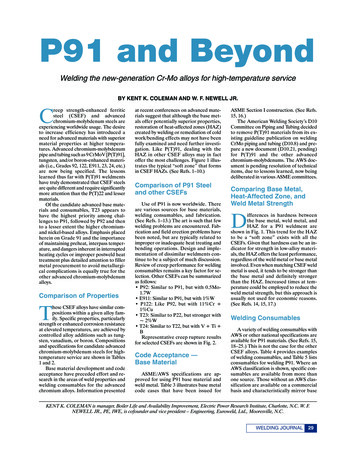
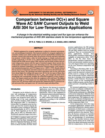
Toma 9-11 Layout 1 8/15/11 9:01 AM Page 154WELDING RESEARCHFig 1 — Chromium and nickel contents in weld beads according to the experimental conditions used in this work.Fig. 2 — Change in weld metal chemical composition as a function of experimental welding conditions. Weld metal is compared to base metal chemicalcomposition.Fig. 3 — Dilution in weld bead as a function of experimental weldingconditions.Fig. 4 — Comparison among oxygen and nitrogen contents for base metal(BM) and four experimental weld metal conditions.toughness measured by Charpy V-notch(CVN) absorbed impact energy or cracktip opening displacement (CTOD) decreases with temperature.Furthermore, in the case of stainlesssteel weld metal, the matrix is a dual-phasetype, with ferrite and austenite, dependingupon the solidification mode (Refs. 7–10).The presence of ferrite, even in smallamounts, usually less than 10%, can alsogenerate a ductile or a brittle path, depending upon the test temperature. Athigh and room temperatures, ferrite isductile and, consequently, its volumetricfraction and its morphology don’t controlthe rupture mechanism. In this case, thefracture mechanism is due to the volumetric fraction of inclusions. At low or cryo-genic temperatures, ferrite can be brittleand can lead to reduction in the toughnessof the weld by a cleavage mechanism.The ferrite morphology and its volumetric fraction in the weld metal are important in determining the crackingmechanism at low and cryogenic temperatures. Solidification mode, ferrite morphology, and its amount are determinedTable 1 — Tension Test Results for All Tested SamplesTensile Strength (MPa)ExperimentalConditionNumberof ile Strength(MPa)Sample FailureLocalization515Weld 4(AC/A)606.0154-s SEPTEMBER 2011, VOL. 90
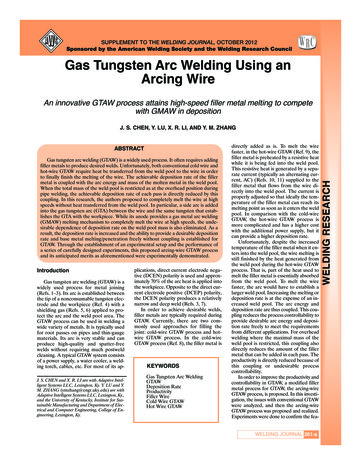
Fig. 5 — Comparison among sulfur, phosphorus and carbon contents for basemetal (BM) and four experimental weld metal conditions.Fig. 6 — Change in C, S, P, O, and N chemical composition as a function ofexperimental welding conditions. Weld metal is compared to base metal chemical composition.Fig. 7 — Weld bead delta ferrite content for the experimental weldingconditions.Fig. 8 — Creq/Nieq ratio for the experimental conditions used in this work.by chemical composition (Creq/Nieq ratio)and by the orientation between 100 γdirection and heat flow flux direction during weld pool solidification (Refs. 11–13).As presented before, the Creq/Nieqratio is one factor that determines theweld pool solidification mode, ferrite morphology, and the volumetric fraction ofdelta ferrite in the weld bead (Refs. 7–10).If Creq/Nieq ratio is below 1.48, the solidification mode produces a weld bead withan austenitic microstructure. When theCreq/Nieq ratio is between 1.48 and 1.95, aferrite-austenite solidification mode takesplace in the weld pool, which produces anaustenitic-ferritic microstructure with 2 to10% ferrite. Vermicular ferrite morphology is more frequent than lath ferritewhen Creq/Nieq ratio is in the lower part ofthe 1.48 to 1.95 range. Lath ferrite usuallyoccurs more often than vermicular morphology while Creq/Nieq ratio is closer to1.95. As Creq/Nieq ratio is higher than 1.95,a primary ferrite microstructure is produced in the weld bead, with austenite precipitation during cooling by ferritedecomposition.The weld pool chemical compositioncan be changed due to thermochemicaland electrochemical reactions on themolten droplet at the wire tip, duringdroplet transfer, and in the weld pool incontact with the electric arc or molten slagin submerged arc welding (SAW) and electroslag welding (ESW) processes (Refs.14–17). According to Blander and Olson(Ref. 14), the anodic reaction (electrodepositive) at the molten droplet-slag interface in the wire tip is responsible for theoxide formation, and the anodic reaction(electrode negative) of the metal ion is responsible for the electrodeposition of metals at the weld pool. The chemicalcomposition due to cathodic reactions isadjusted by chemical reactions. Also, thewelding pool chemical composition can bechanged due to dilution. Usually, directcurrent (electrode positive) polarity produces a higher penetration and direct current (electrode negative) increasesdeposition rate, using the same SAWprocess flux type. Thus, using direct current (electrode positive) or alternatingcurrent during SAW can produce a different chemical composition in the weld pool.Therefore, the change in chemical composition can alter the ferrite morphology.The heat flow flux condition can also affect the ferrite morphology. In the casewhere 100 γ directions and heat flowTable 2 — Charpy V-Notch Test Results at –100 C (–73 F) for All Experimental ConditionsExperimentalConditionMean Absorbed Energy(J)Mean LateralExpansion (mm)1(AC/N)65 50.783 0.0972(DC/N)56 50.740 0.0683(DC/A)36 50.661 0.0874(AC/A)53 60.694 0.134WELDING JOURNAL 155-sWELDING RESEARCHToma 9-11 Layout 1 8/15/11 8:51 AM Page 155
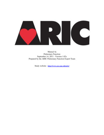
Toma 9-11 Layout 1 8/11/11 4:29 PM Page 156ABFig. 9 — Typical ferrite morphology for 3(DC/A) weld metal experiment. A — Presents both ferrites morphologies types; B — detail of a ferrite transition morphology region. Electrolytic etching: oxalic acid 10%. Optical microscope.WELDING RESEARCHAFig. 10 — Dimple mean size as a function of oxygen content in weld metalfor the experimental conditions tested in this work.flux direction during weld pool solidification are parallel, delta ferrite can beformed with a lath or vermicular morphology, depending upon the existence, ornot, of Kurdjumov-Sachs orientation relationship between delta ferrite and austenite (Ref. 12). On the other hand, if the 100 γ direction and heat flow directionduring weld pool solidification are not parallel, the delta ferrite morphology is vermicular (Ref. 12).These delta ferrite morphologies andvolumetric fraction are also related to thetoughness of the microstructure. Depending upon the temperature, a smallscale yielding (cryogenic temperature) ora large-scale yielding (low temperature,room temperature, and above) conditiontakes place during crack propagation.Lath ferrite usually presents bettertoughness than vermicular ferrite in anaustenitic-ferritic matrix for small-scaleyielding (Ref. 12). This is due to the crackpropagation in the ferrite at low or cryogenic temperatures. Vermicular ferrite isusually a more continuous and aligned156-s SEPTEMBER 2011, VOL. 90BFig. 11 — Mechanism of low and cryogenic temperatures for two ferritesmorphologies Refs. 11,12. A — Vermicular ferrite morphology B — lathferrite morphology.ferrite than lath ferrite, which has a ferrite crack propagation mean path lowerthan vermicular ferrite, mainly due to theductile austenite that acts as a crackarrester.The objective of this work is to determine the differences in chemical composition and low-temperature mechanicalproperties of an AISI 304 base metalweld joint caused by changing submergedarc welding parameters such as flux type(neutral and alloyed fluxes) and electriccondition (direct current electrode positive or square wave alternating current).Experimental ProcedureA 25-mm- (1-in.-) thick AISI 304 stainless steel base metal was welded by theSAW process using an AWS A5.9 ER308Lfiller metal with 3.25-mm (1 8-in.) diameterand two kinds of fluxes: neutral andchromium autocompensating alloyed. Thewelds were made by a constant voltagepower source with two electrical outputtypes: direct current electrode positive andbalanced square wave alternating current.Samples 1 and 4 were made with alternating current, balanced square wave with a70-Hz frequency with neutral (AC/N) andchromium autocompensating alloyedfluxes (AC/A), respectively. Samples 2 and3 were welded with continuous currentelectrode positive, using neutral (DC/N)and chromium autocompensating alloyedfluxes (DC/A), in that order. All four samples were welded with a mean heat inputclose to 2.2 kJ/mm (0.87 kJ/in.) and a double-V bevel type.The welded joints were analyzed by different methods. The chemical compositionof base metal, weld metal, and filler metalwere analyzed using an optical emissionspectroscopy and LECO equipment forcarbon, sulfur, oxygen, and nitrogen measurements. Dilution was determined by aratio between melted base metal area toweld metal area. Microstructure characterization was done using an optical microscope and scanning electron microscopewith an energy dispersive microanalysis.Samples observed in the optical microscope
Toma 9-11 Layout 1 8/11/11 4:30 PM Page 157AFig. 12 — A view of CVN crack propagation. A — Flat propagation type insample 3DC/A; B — rounded propagation type for sample 4(AC/A).ABBFi
WELDING JOURNAL 155-s WELDING RESEARCH Fig. 5 — Comparison among sulfur, phosphorus and carbon contents for base metal (BM) and four experimental weld metal conditions. Fig. 7 — Weld bead delta ferrite content for the experimental welding conditions. Fig. 6 — Change in C, S, P, O, and N chemical composition as a function of experimental welding conditions. Weld metal is