Transcription
Chen 10-12 Layout 1 9/6/12 2:23 PM Page 261SUPPLEMENT TO THE WELDING JOURNAL, OCTOBER 2012Sponsored by the American Welding Society and the Welding Research CouncilGas Tungsten Arc Welding Using anArcing WireAn innovative GTAW process attains high-speed filler metal melting to competewith GMAW in depositionABSTRACTGas tungsten arc welding (GTAW) is a widely used process. It often requires addingfiller metals to produce desired welds. Unfortunately, both conventional cold wire andhot-wire GTAW require heat be transferred from the weld pool to the wire in orderto finally finish the melting of the wire. The achievable deposition rate of the fillermetal is coupled with the arc energy and mass of the molten metal in the weld pool.When the total mass of the weld pool is restricted as at the overhead position duringpipe welding, the achievable deposition rate of each pass is directly reduced by thiscoupling. In this research, the authors proposed to completely melt the wire at highspeeds without heat transferred from the weld pool. In particular, a side arc is addedinto the gas tungsten arc (GTA) between the wire and the same tungsten that establishes the GTA with the workpiece. While its anode provides a gas metal arc welding(GMAW) melting mechanism to completely melt the wire at high speeds, the undesirable dependence of deposition rate on the weld pool mass is also eliminated. As aresult, the deposition rate is increased and the ability to provide a desirable depositionrate and base metal melting/penetration freely without coupling is established forGTAW. Through the establishment of an experimental setup and the performance ofa series of carefully designed experiments, this proposed arcing-wire GTAW processand its anticipated merits as aforementioned were experimentally demonstrated.IntroductionGas tungsten arc welding (GTAW) is awidely used process for metal joining(Refs. 1–3). Its arc is established betweenthe tip of a nonconsumable tungsten electrode and the workpiece (Ref. 4) with ashielding gas (Refs. 5, 6) applied to protect the arc and the weld pool area. TheGTAW process can be used in welding awide variety of metals. It is typically usedfor root passes on pipes and thin-gaugematerials. Its arc is very stable and canproduce high-quality and spatter-freewelds without requiring much postweldcleaning. A typical GTAW system consistsof a power supply, a water cooler, a welding torch, cables, etc. For most of its apJ. S. CHEN and X. R. LI are with Adaptive Intelligent Systems LLC, Lexington, Ky. Y. LU and Y.M. ZHANG (ymzhang@engr.uky.edu) are withAdaptive Intelligent Systems LLC, Lexington, Ky.,and the University of Kentucky, Institute for Sustainable Manufacturing and Department of Electrical and Computer Engineering, College of Engineering, Lexington, Ky.plications, direct current electrode negative (DCEN) polarity is used and approximately 70% of the arc heat is applied intothe workpiece. Opposite to the direct current electrode positive (DCEP) polarity,the DCEN polarity produces a relativelynarrow and deep weld (Refs. 3, 7).In order to achieve desirable welds,filler metals are typically required duringGTAW. Currently, there are two commonly used approaches for filling thejoint: cold-wire GTAW process and hotwire GTAW process. In the cold-wireGTAW process (Ref. 8), the filler metal isKEYWORDSGas Tungsten Arc WeldingGTAWDeposition RateProductivityFiller WireCold Wire GTAWHot Wire GTAWdirectly added as is. To melt the wirefaster, in the hot-wire GTAW (Ref. 9), thefiller metal is preheated by a resistive heatwhile it is being fed into the weld pool.This resistive heat is generated by a separate current (typically an alternating current, AC) (Refs. 10, 11) supplied to thefiller metal that flows from the wire directly into the weld pool. The current isproperly adjusted so that ideally the temperature of the filler metal can reach itsmelting point as soon as it enters the weldpool. In comparison with the cold-wireGTAW, the hot-wire GTAW process ismore complicated and has a higher costwith the additional power supply, but itcan provide a higher deposition rate.Unfortunately, despite the increasedtemperature of the filler metal when it enters into the weld pool, the wire melting isstill finished by the heat generated fromthe weld pool during the hot-wire GTAWprocess. That is, part of the heat used tomelt the filler metal is essentially absorbedfrom the weld pool. To melt the wirefaster, the arc would have to establish alarger weld pool. Increasing the melting ordeposition rate is at the expense of an increased weld pool. The arc energy anddeposition rate are thus coupled. This coupling reduces the process controllability toprovide desirable arc energy and deposition rate freely to meet the requirementsfrom different applications. For overheadwelding where the maximal mass of theweld pool is restricted, this coupling alsodirectly reduces the amount of the fillermetal that can be added in each pass. Theproductivity is directly reduced because ofthis coupling or undesirable processcontrollability.In order to improve the productivity andcontrollability in GTAW, a modified fillermetal process for GTAW, the arcing-wireGTAW process, is proposed. In this investigation, the issues with conventional GTAWwere analyzed, and then the arcing-wireGTAW process was proposed and realized.Experiments were done to confirm the fea-WELDING JOURNAL 261-sWELDING RESEARCHJ. S. CHEN, Y. LU, X. R. LI, AND Y. M. ZHANG
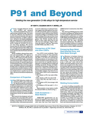
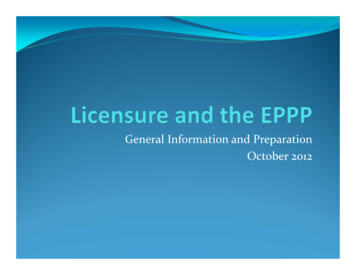
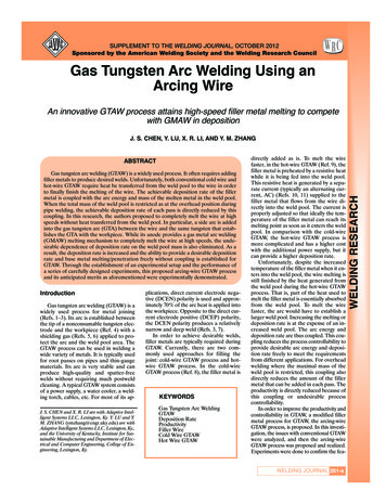
Chen 10-12 Layout 1 9/6/12 2:23 PM Page 262Fig. 2 — Plot of deposition rate vs. arc energy in cold-wire and hot-wireGTAW processes (Ref. 14).Fig. 1 — Principles of hot-wire GTAW system (Ref. 12).WELDING RESEARCHBAFig. 4 — The comparison of hot-wire welding and modified filler metalGTAW process. A — Arc and weld pool in hot-wire GTAW; B — arcs andweld pool in arcing-wire GTAW.Fig. 3 — Arc-assisted hot-wire GTAW (Ref. 15).sibility and effectiveness of the proposedarcing-wire GTAW in decoupling the arc energy and the deposition rate. The achievablecombination range of GTAW current vs.wire melting current are given to demonstrate the desirable controllability of the arcing-wire process for separate control of arcenergy and deposition.Analysis of Conventional GTAWIn the conventional cold-wire GTAWprocess, the filler metal is primarily meltedwithin and by the molten pool. In otherwords, the heat used to melt the fillermetal is essentially absorbed from theweld pool on the workpiece. The wire deposition rate is limited by the heat inputinto the workpiece. Attempting to increasethis rate will have to be at the expense ofincreased heat input.As a further development to the coldwire GTAW process, the hot-wire GTAWprocess was invented by Manz and thenTable 1 — Comparison of Energy EfficienciesCaseWire MaterialExtension (mm)Wire Resistance (Ω)Cable Length (m)Cable Resistance (Ω)Wire Current (A)Energy Efficiency: Hot-wireEnergy Efficiency: Arcing-wireImprovement Ratiop I w2 Rw1234Carbon 3100.0021420030%75%247%Carbon 200.0042820014%73%517%262-s OCTOBER 2012, VOL. 91developed by Linde Division of UnionCarbide in 1964 (Ref. 13). Figure 1 illustrates the block diagram of a typical hotwire GTAW system. As shown in Fig. 1, ahot-wire loop commonly includes a wirefeeder, a wire heating power supply (typically alternating current), a contact tube,and a ceramic isolation guide. After thegas tungsten arc is established, the wire isfed into the weld pool. As a result, the hotwire current loop is closed and the currentflowing through the wire generates the resistance heat in the wire.( )Rw ρl / π r 2(1)(2)where P is the power of the resistanceheat; Iw is the current passing through thewire; Rw is the resistance of the wire extension; ρ is the electrical resistivity of thewire; l is the length of the wire extension;and r is the radius of the wire.It is clear that the wire diameter and
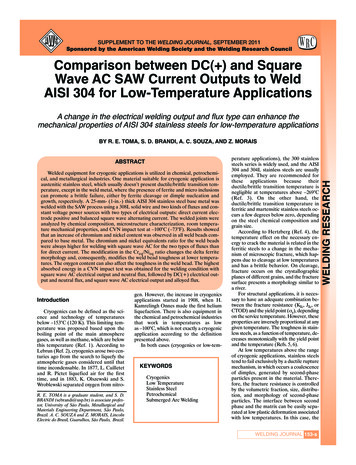
Chen 10-12 Layout 1 9/6/12 2:23 PM Page 263BAFig. 6 — Welding currents and voltages in Experiment No.1.Fig. 7 — Weld bead of Experiment No. 1 (welding direction: left to right).Fig. 8 — Welding currents and voltages in Experiment No. 2.Fig. 9 — Weld bead of Experiment No. 2 (welding direction: left to right).Fig. 10 — Welding currents and voltages in Experiment No. 3.Fig. 11 — Weld bead of Experiment No. 3 (welding direction: left to right).length of wire extension determine the resistance and thus the resistance heat. Byusing this heat, ideally the filler metal is ableto heat up close to its melting point. As a result, the wire deposition rate can be increased significantly. Figure 2 shows thecomparison of the deposition rate betweenthe cold- and hot-wire GTAW processes(Ref. 14). It can be seen that the arc energyin the hot-wire GTAW significantly increases the deposition rate. That is, the deposition rate is coupled with the arc energy.In addition to the coupling between thedeposition rate and arc energy, there areother issues associated with the hot-wireGTAW. One of these issues is that its dep-osition rate is still limited especially whenthe electrical resistivity of the wire material is relatively low. To resolve this issue,a second arc was added to increase thepreheat temperature of the wire using thesystem as shown in Fig. 3 (Refs. 15, 16).This effort is a demonstration of theawareness of the welding communityWELDING JOURNAL 263-sWELDING RESEARCHFig. 5 — Arcing-wire GTAW system. A — System diagram; B — system.
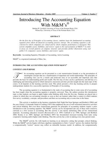
Chen 10-12 Layout 1 9/10/12 1:35 PM Page 264Fig. 13 — Weld bead of Experiment No. 4 (welding direction: left to right).Fig. 12 — Welding currents and voltages in Experiment No. 4.Fig. 14 — Welding currents and voltages in Experiment No. 5.WELDING RESEARCHabout the dependence of the effectivenessof the hot-wire GTAW on the wire material. Another issue is that, in all cases forhot-wire GTAW process, the resistanceheat generated within the cable becomessignificant in comparison with the effective heat that preheats the wire. This partof resistance heat is not only wasted ration-inconvenience of the cable.To overcome the issues associated withthe hot-wire GTAW, the wire meltingmechanism in GMAW is introduced intothe GTAW, and the arcing-wire GTAW isproposed.Arcing-Wire GTAWThe authors propose an innovativelymodified GTAW, namely the arcing-wireGTAW, as being compared with the hotwire GTAW in Fig. 4. As shown in Fig. 4B,a wire with higher potential than the tungsten is sent into the main GTA. The potential difference between the wire andtungsten can be established using a secondFig. 15 — Weld bead of Experiment No. 5 (welding direction: left to right).power supply. As a result, a side arc is established between the tip of the tungstenand the filler metal inside the main GTA.The primary difference between thehot-wire GTAW process and the arcingwire GTAW process lies in the meltingmechanism for the filler metal. As can beseen in Fig. 4A, in the hot-wire GTAWprocess, the filler metal is preheated atfirst by the resistance heat generated bythe current inside the wire, and thenmelted within the weld pool. Similarly, asin cold-wire GTAW, the heat that finishesthe melting of the filler metal is still theheat absorbed from the weld pool. Thereis no gap between the filler metal and weldpool. However, in the arcing-wire GTAWprocess shown as Fig. 4B, the wire is actually completely melted by the side arc established between the tungsten and thewire. The wire can thus be melted similarlyas in GMAW process at high speeds despite possible low resistivity of the wire.Further, this melting process does not depend on the weld pool. The coupling between the deposition rate and arc energy isdecoupled.Table 2 — Arcing-Wire Experimental System ComponentsEquipment and AccessoriesModel, Material or SizeGTA power supplyWire heating power supplyWire feederGTAW torchFiller metal torchDiameter of filler metalShielding gas of GTAW torchShielding gas of filler metalThermal Arc Power-Master 500Miller PM 200Miller S-74DWeldcraft WP-18P 500-A GTAW torchBernard GMAW gun — 400-A Q-gun0.045 in.Pure argonnone264-s OCTOBER 2012, VOL. 91Comparative AnalysisMelting SpeedThe hot-wire GTAW uses the resistiveheat to preheat the wire at power Pw I2wRw IwVw where Iw ,Vw, and Rw are thewire current, voltage, and resistance. In thearcing-wire GTAW, this resistive heat stillheats the wire, but an additional power,IwVanode where Vanode is the anode voltagedrop, is added. The heat the arcing wireGTAW provides to heat/melt the wire isI wVw lwVanodelwVw 1 Vanode / Vwk (3)times of that provided by the hot-wireGTAW. Because Rw is small for the metalwire as an excellent conductor, Vw IwRwis typically much smaller than Vanode unless an extremely high current is used. Thewire in the arcing-wire GTAW is melted atthe same speed as in GMAW for the same(wire) current. It is true that the hot-wireGTAW also uses part of the heat from theweld pool to finish the melting of the wire.However, the deposition rate achievableby hot-wire GTAW is much lower thanthat achievable by GMAW. Because thedeposition rate achievable by arcing-wireis the same as that by GMAW, the deposition/melting rate for the arcing-wire ismuch improved.Energy EfficiencyDenote the resistance of the cable asRc. This is apparent that the energy efficiency for hot-wire GTAW is
Fig. 16 — Welding currents and voltages in Experiment No. 6.Fig. 17 — Weld bead of Experiment No. 6 (welding direction: left to right).Fig. 18 — Welding currents and voltages in Experiment No. 7.Fig. 19 — Weld bead of Experiment No. 7 (welding direction: left to right).Fig. 20 — Welding currents and voltages in Experiment No. 8.Fig. 21 — Weld bead of Experiment No. 8 (welding direction: left to right).RwRc Rw(4)For the arcing-wire GTAW, this efficiency isη2 (IwRw Vanode)/(Vanode Vcathode Vvolume IwRc IwRw)(5)η1 where Vanode
Gas tungsten arc welding (GTAW) is a widely used process for metal joining (Refs. 1–3). Its arc is established between the tip of a nonconsumable tungsten elec-trode and the workpiece (Ref. 4) with a shielding gas (Refs. 5, 6) applied to pro-tect the arc and the weld pool area. The GTAW process can be used in welding a wide variety of metals. It is typically used