Transcription
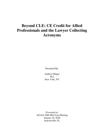
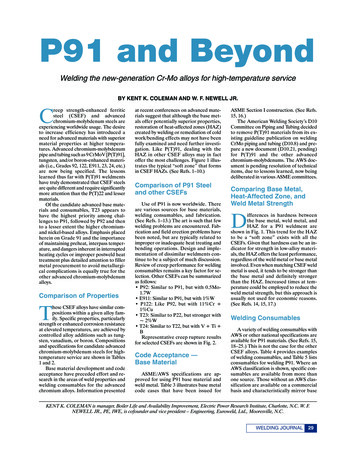
Newell Feature August 2007:Layout 17/9/0711:02 AMPage 29P91 and BeyondWelding the new-generation Cr-Mo alloys for high-temperature serviceBY KENT K. COLEMAN AND W. F. NEWELL JR.reep strength-enhanced ferriticsteel (CSEF) and advancedchromium-molybdenum steels areexperiencing worldwide usage. The desireto increase efficiency has introduced aneed for advanced materials with superiormaterial properties at higher temperatures. Advanced chromium-molybdenumpipe and tubing such as 9 CrMoV [P(T)91],tungsten, and/or boron-enhanced materials (i.e., Grades 92, 122, E911, 23, 24, etc.)are now being specified. The lessonslearned thus far with P(T)91 weldmentshave truly demonstrated that CSEF steelsare quite different and require significantlymore attention than the P(T)22 and lessermaterials.Of the candidate advanced base materials and consumables, T23 appears tohave the highest priority among challenges to P91, followed by P92 and thento a lesser extent the higher chromiumand nickel-based alloys. Emphasis placedherein on Grade 91 and the importanceof maintaining preheat, interpass temperature, and dangers inherent in interruptedheating cycles or improper postweld heattreatment plus detailed attention to fillermetal procurement to avoid metallurgical complications is equally true for theother advanced chromium-molybdenumalloys.CComparison of Propertieshese CSEF alloys have similar compositions within a given alloy family. Specific properties, particularlystrength or enhanced corrosion resistanceat elevated temperatures, are achieved bycontrolled alloy additions such as tungsten, vanadium, or boron. Compositionsand specifications for candidate advancedchromium-molybdenum steels for hightemperature service are shown in Tables1 and 2.Base material development and codeacceptance have preceded effort and research in the areas of weld properties andwelding consumables for the advancedchromium alloys. Information presentedTat recent conferences on advanced materials suggest that although the base metals offer potentially superior properties,restoration of heat-affected zones (HAZ)created by welding or remediation of coldwork/bending effects may not have beenfully examined and need further investigation. Like P(T)91, dealing with theHAZ in other CSEF alloys may in factoffer the most challenges. Figure 1 illustrates the typical “soft zone” that formsin CSEF HAZs. (See Refs. 1–10.)Comparison of P91 Steeland other CSEFsUse of P91 is now worldwide. Thereare various sources for base materials,welding consumables, and fabrication.(See Refs. 1–13.) The art is such that fewwelding problems are encountered. Fabrication and field erection problems havebeen noted, but are typically related toimproper or inadequate heat treating andbending operations. Design and implementation of dissimilar weldments continue to be a subject of much discussion.Review of creep performance for weldingconsumables remains a key factor for selection. Other CSEFs can be summarizedas follows: P92: Similar to P91, but with 0.5Mo1.7W E911: Similar to P91, but with 1%W P122: Like P92, but with 11%Cr 1%Cu T23: Similar to P22, but stronger with 2%W T24: Similar to T22, but with V Ti BRepresentative creep rupture resultsfor selected CSEFs are shown in Fig. 2.Code Acceptance —Base MaterialASME/AWS specifications are approved for using P91 base material andweld metal. Table 3 illustrates base metalcode cases that have been issued forASME Section I construction. (See Refs.15, 16.)The American Welding Society’s D10Committee on Piping and Tubing decidedto remove P(T)91 materials from its existing guideline publication on weldingCrMo piping and tubing (D10.8) and prepare a new document (D10.21, pending)for P(T)91 and the other advancedchromium-molybdenums. The AWS document is pending resolution of technicalitems, due to lessons learned, now beingdeliberated in various ASME committees.Comparing Base Metal,Heat-Affected Zone, andWeld Metal Strengthifferences in hardness betweenthe base metal, weld metal, andHAZ for a P91 weldment areshown in Fig. 1. This trend for the HAZto be a “soft zone” exists with all theCSEFs. Given that hardness can be an indicator for strength in low-alloy materials, the HAZ offers the least performance,regardless of the weld metal or base metalinvolved. Even when matching CSEF weldmetal is used, it tends to be stronger thanthe base metal and definitely strongerthan the HAZ. Increased times at temperature could be employed to reduce theweld metal strength, but this approach isusually not used for economic reasons.(See Refs. 14, 15, 17.)DWelding ConsumablesA variety of welding consumables withAWS or other national specifications areavailable for P91 materials. (See Refs. 15,18–25.) This is not the case for the otherCSEF alloys. Table 4 provides examplesof welding consumables, and Table 5 listsconsumables for welding P91. Where anAWS classification is shown, specific consumables are available from more thanone source. Those without an AWS classification are available on a commercialbasis and characteristically mirror baseKENT K. COLEMAN is manager, Boiler Life and Availability Improvement, Electric Power Research Institute, Charlotte, N.C. W. F.NEWELL JR., PE, IWE, is cofounder and vice president – Engineering, Euroweld, Ltd., Mooresville, N.C.WELDING JOURNAL29
Newell Feature August 2007:Layout 17/9/0711:02 AMPage 30Fig. 1 — Representative microhardness across a typical P91 weldment(Ref. 10).metal compositions. In most cases, AWSA5.01, Filler Metal Procurement Guidelines, provides the means to specify andobtain satisfactory material for materialswith a classification and those that mustbe ordered with the “-G” classification.elding consumables for Type P/T92, 122, 23, or 24 alloys do nothave recognized specifications atthis writing. Filler metals for these alloysare formulated to provide weld depositssimilar in composition and performanceas the base material. In lieu of a specification, manufacturers should be consultedfor consumables that are available forthese alloys. Typical compositions areshown in Table 6.Crater cracking and other undesirablegrain boundary phenomena can be minimized by ordering weld metal with lowresidual element content and a –15 coating as well as observing a Mn/S ratiogreater than 50. These recommendationsare offered to reduce the potential forproblems that occur as a result of lowWFig. 2 — 103 h creep rupture values of T/P22, T/P23, T/P24, andT/P91 as a function of temperature. (Kimura/Prager, Refs. 13–15).melting constituents or other precipitatesthat influence grain boundary integrity.Shielded metal arc welding (SMAW)and flux cored arc welding (FCAW) electrodes should undergo actual chemicaland mechanical testing. A satisfactorychemical analysis does not guarantee acceptable mechanical properties, especiallytoughness. Mechanical testing, includingtensile and impact tests, is recommendedon a lot to lot, per size per diameter basis.Testing and reporting only actualchemical analysis on a per size, per heatsupplied basis for gas tungsten arc welding (GTAW) and submerged arc welding(SAW) bare wires is normally satisfactory.Heating Operationsroper application of heating operations is critical to success. Application and rigorous control of preheat,interpass, and postweld heat treatmentoperations are required to ensure that de-Psired toughness and creep resistance areobtained. Control of preheat and interpass temperatures and even postbakingoperations are necessary to avoid hydrogen retention/cracking problems in thisextremely hardenable alloy family. Flame,furnace heating, electrical resistance, andelectrical induction heating have beenused successfully. Temperature monitoring and control of thermal gradients is extremely important. For these reasons,local flame heating is not recommendedand should not be permitted. Changes insection thickness, chimney, and positioneffects must also be considered. If unknown, mock-ups should be used to establish heated band, soak times, and actual thermal gradients. (See Refs. 18,22–26.)PreheatThe literature suggests that 200 C( 400 F) is adequate for preheating P91and P92 weldments. Fabricators typicallyTable 1 — CSEF Base Material Typical Composition RangesBase Material T23T24P1220.08–0.120.30–0.600.20–0.50 0.010 0.0208.00–9.50 �0.070— 0.040—0.07–0.130.30–0.60 0.50 0.010 0.0208.50–9.50 90.030–0.07010–60 ppm 0.040—0.10–0.130.30–0.600.10–0.30 0.010 0.0208.50–9.50( 100.050–0.080———0.04–0.100.10–0.60 0.50 0.010 .300.02–0.08 0.0305–60 ppm 0.030—0.05–0.100.30–0.700.15–0.45 0.010 0.0202.2–2.6——0.90–1.10—0.20–0.30— 0.01215–70 ppm 0.0200.05–0.100.07–0.140.30–0.70 0.50 0.010 0.02010.00–12.50 04–0.100.040–0.10 0.005 0.040—AUGUST 2007
Newell Feature August 2007:Layout 17/9/0711:03 AMPage 31Table 5 — Consumables Listed in ASME/AWSSpecifications for Welding P91Table 2 — Example Specification Designations (Refs. 1–7, 11, 12)AlloyCode/JurisdictionSpecification or Designation91ASTMA 213 T91 (seamless tubes)A 335 P91 (seamless pipes)A 387 Gr 91 (plates)A 182 / A336 F91 (forgings)A 217 C12A (castings)A 234 WP91A 369 FP91EN 10222-2; 1.4903 (X10CrMoVNb 9-1)1503 Gr 91NF A-49213/A-49219 Gr TU Z 10CDVNb 09-01DIN/ENBSAFNOR911JapanDIN92ASTM1.4905 (X11CrMoWVNb 9 1 1)G-X12CrMoWVNbN 10 1 1 (cast)A 213 T92 (seamless tubes)A 335 P92 (seamless pipes)A 387 Gr 92 (plates)A 182 F92 (forgings)A 369 FP92 (forged & bored pipe)X10CrWMoVNb 9-2Nf 616KA-STPA29 (pie)KA-SFVAF29 (forging)KA-STBA29 (tube)HCM12AHCM12, KA-SUS410J2TBA 213 T23 (seamless 9E90XX-B9EB9 fluxER90S-B9E91T1-B9lems with interpass temperature on heavysections (Refs. 9, 20).Postweld ‘Bake-Out’postweld “bake-out” may be ofcritical importance, especially forheavy sections or where flux-typeprocesses are used. This involves maintaining the preheat/interpass temperaturefor an extended period of time subsequentto interruption or completion of the weld.When establishing the length of time necessary, factors that play a role includethickness of the material, length of timethe weldment has been exposed to theheat regime, and the extent of “low hydrogen” practices used. Where properpreheat, consumables, and storage/handling are implemented, bake-outs can beminimized or even eliminated.AHCM2SKA-STPA24J1 (pipe)KA-SFVAF22AJ1 (forging)KA-STBA24J1 (tube)7 CrMoVTiB 10-10GermanyProcessInterruption of Heating CycleTable 3 — ASME Code AcceptanceTrade NameGradeMaterial (seamless)Code CaseIssue t 8, 1994August 8, 1994June 5, 1995May 2, 2000Table 4 — Example Welding *E9015-B9ER90S-B9E91T1-B9EB9XXXXXXXXXXXXXX* Filler metals available to manufacturer or OEM specifications only.aim for 200 –250 C ( 400 –500 F), but willgo as low as 121 C (250 F) for root and hotpass layers, thin-walled components, orwhere GTAW is utilized. Experience indicates that no elevated preheat is requiredfor T23 or T24 weldments; however, somecode bodies including ASME require preheat or postweld heat treatment (PWHT)for these alloys (Table 7).InterpassA typical maximum interpass temperature is 300 C (572 F); less is acceptablebut no more than 370 C (700 F). The interpass maximum helps to prevent thepossibility of hot cracking due to the silicon and niobium content of the weldmetal. Field operations rarely have prob-Interruption of the heat cycle shouldbe avoided if at all possible. The mass ofthe weldment must be considered. Increases in pipe wall thickness translateinto increases in the restraint on the weldand the cooling rate from welding temperatures. Therefore, the weld area is subjected to high residual stresses at a timewhen it may have minimum section thickness (or strength) and be less ductile. Ifinterruption is unavoidable, at least onefourth of the wall thickness should be deposited and preheat must be maintaineduntil the groove is completed or a postbake implemented.Postweld Heat Treatmentpplication of PWHT is absolutelynecessary with Grade 91, 911, 92,and 122 weldments, regardless ofdiameter or thickness. PWHT is one of the most important factors in producing satisfactory weldments. The PWHT methodology andimplementation must be verified to ensure that the weldments are actually receiving PWHT at the proper temperature. Additional thermocouples or qualification testing may be required.Proper tempering of the martensiticmicrostructure is essential for obtainingAWELDING JOURNAL31
Newell Feature August 2007:Layout 17/9/0711:03 AMPage 32Table 6 — Typical Weld Metal Deposit Compositions and Mechanical Properties (Refs. 15, 18–25)Weld MetalCMnP, maxS, maxSi, maxCrMoWNi, maxVNbN, maxAl, maxBTiCu, maxUlt, ksiYield, ksiElong. , as-welded)[90–102; 1365 2 h]581(126, as-welded)[74–89; 1365 2 h]201(18–19, as-welded)[19; 1365 2 03-0.09—852(116–136, as-welded)[91–126; 1365F 2 h]652(96–102, as-welded)[74–86; 1365F 2 h]202(17–19, as-welded)[20–22; 1365F 2 0.070.04–0.070.020.005——903(107–116; 1400 F 2–4 0–0.601.5–2.00.80 0.005—0.15904(107–116; 1400F 2–4 h)643(91–102; 1400 F 2–4 h)644(91–102; 1400F 2–4 h)203(16–22; 1400 F 2–4 h)204(16–22; 1400F 2–4 h)1. Base Material; ASME Code Case 21992. Base Material; Vallourec-Mannessman3. Base Material; ASME Code Case
A variety of welding consumables with AWS or other national specifications are available for P91 materials. (See Refs. 15, 18–25.) This is not the case for the other CSEF alloys. Table 4 provides examples of welding consumables, and Table 5 lists consumables for welding P91. Where an AWS classification is shown, specific con-sumables are available from more than one source. Those without