Transcription
MH fluid coolerengineering dataand specifications
MH Fluid Cooler — Table of ContentsEngineering DataSchematic – Single-Flow Models 4Schematic – Double-Flow Models 5Support 6Freeze Prevention 7Water Quality 8Specifications / BaseBase 9Thermal Performance 9Performance Warranty 10Coil 10Design Loading 10Construction 11Mechanical Equipment 11Fill, Louvers and Drift Eliminators 12Distribution Basin 13Casing, Fan Deck and Fan Guard 13Access 14Collection Basin 14Warranty 14Specifications / OptionsAlternate Material OptionsAll Stainless Steel Fluid Cooler 15Stainless Steel Collection Basin 15Stainless Steel Distribution Basin 16Copper Coil 16Stainless Steel Coil 16Convenience and Safety OptionsGuardrail and Ladder 17Distribution Basin Access Platform 17Ladder Extension 17Ladder Safety Cage 17Ladder Safety Gate 18Access Door Platform 18Plenum Walkway 18Interior Mechanical Equipment Access Platform 19Control OptionsCombination Fan and Pump Motor Control Panel 19Pump Motor Control Panel 20Vibration Limit Switch 20Basin Heater 20Water Level Control 21Fan Motor Variable Speed Drive 21Miscellaneous OptionsDampers 24Motor Out of the Airstream 24High Temperature Fill 24Air Inlet Screens 24FM Approval 25Basin Sweeper Piping 25Sound Control 25Inlet Sound Attenuation 26Quiet Fan 26Ultra Quiet Fan 26Dry Cooling Operation 27Extended Geareducer Lube Line with Dip Stick 27Fan Cylinder Extensions 272
MH Fluid CoolerThe Marley MH Fluid Cooler is one of the most efficientclosed-circuit heat rejection products on the market—andyour best choice for industrial and HVAC applications.By keeping the process fluid in a clean, closed loop,and combining the function of a cooling tower and heatexchanger into one system, the MH Fluid Cooler canprovide superior operational and maintenance benefits.The specifications portion of this publication not only relatesthe language to use in describing an appropriate MH FluidCooler—but also defines why certain items and features areimportant enough to specify with the intention of insistingupon compliance by all bidders. The left hand column ofpages 9 thru 27 provides appropriate text for the variousspecification paragraphs, whereas the right hand columncomments on the meaning of the subject matter andexplains its value.3Pages 9 thru 14 indicate those paragraphs which willresult in the purchase of a basic fluid cooler—one thataccomplishes the specified thermal performance, but whichwill lack many operation—and maintenance-enhancingaccessories and features that are usually desired by thosepersons who are responsible for the continuing operationof the system of which the fluid cooler is part. It will alsoincorporate those standard materials which testing andexperience has proven to provide acceptable longevity innormal operating conditions.Pages 15 thru 27 provide paragraphs intended to add thosefeatures, components, and materials that will customize thefluid cooler to meet the user's requirements.
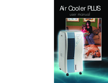
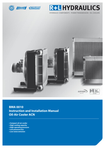
MH Fluid Cooler — Engineering Data: Schematic4Use this data for preliminary layouts only.Obtain current drawing from your Marley salesrepresentative.UPDATE web-based selection software, availableat spxcooling.com/update provides MH Fluid Coolermodel recommendations based on customer'sspecific design requirements.2'-3" MAXPLAN VIEWLWHFLUID OUTINSTALLEDHEIGHTACCESSDOORFLUID INPUMPSIDE ELEVATIONAIR INLET ELEVATIONShipping WeightSteel Coil lbDimensionsModelLMHF7101 A6'-0 3 8"WHWeightHeaviestSection8'-41 16"12'-10 3 4"Shipping WeightCopper Coil 03,1503 - 152MHF7101 B6'-0 8"8'-4 16"14'-4 3 4"5,6203,7904,4303,6803 - 152MHF7101 D6'-0 3 8"8'-41 16"14'-7"5,0503,0504,2903,1503 - 152MHF7101 E6'-0 3 8"8'-41 16"16'-1"5,7903,7904,6003,6803 - 152MHF7103 A9'-0 3 4"8'-41 16"14'-7"7,5904,4606,2803,1505 - 203MHF7103 B9'-0 3 4"8'-41 16"16'-11 8"8,8305,7006,8103,6805 - 203MHF7103 D9'-0 3 4"8'-41 16"15'-113 16"7,8104,4606,5003,3505 - 203MHF7103 E9'-0 3 4"8'-41 16"17'-51 16"9,0505,7007,0303,6805 - 203MHF7105 A12'-0 3 4"8'-41 16"14'-7"9,2705,5307,8004,0607.5 - 255MHF7105 B12'-0 3 4"8'-41 16"16'-11 8"10,6306,8908,5904,8507.5 - 255MHF7105 D12'-0 3 4"8'-41 16"15'-113 16"9,5305,5308,0604,0607.5 - 255MHF7105 E12'-0 3 4"8'-41 16"17'-51 16"10,8906,8908,8504,8507.5 - 255MHF7107 A12'-0 3 4"11'-11"17'-51 8"14,6809,07011,9006,29010 - 407.5MHF7107 B12'-0 3 4"11'-11"18'-111 8"3117,00011,39013,3307,72010 - 407.5MHF7107 D12'-0 4"11'-11"18'-91 4"15,0309,07012,2506,29010 - 407.5MHF7107 E12'-0 3 4"11'-11"20'-31 4"17,35011,39013,6807,72010 - 407.5MHF7109 A18'-0 3 4"11'-11"17'-5 3 16"21,16013,320––15 - 4510MHF7109 B18'-0 3 4"11'-11"18'-113 16"25,68017,750––15 - 45103
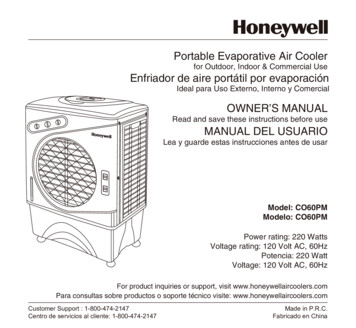
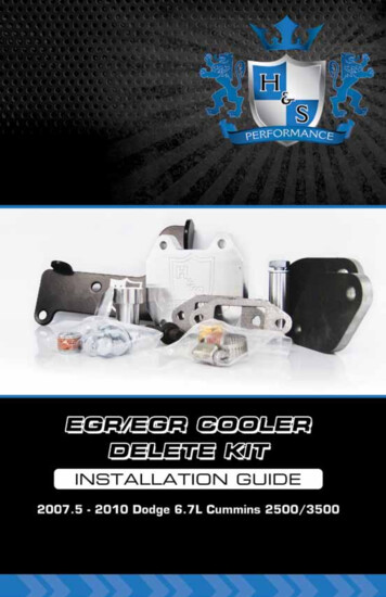
MH Fluid Cooler — Engineering Data: Schematic5Use this data for preliminary layouts only.Obtain current drawing from your Marley salesrepresentative.UPDATE web-based selection software, availableat spxcooling.com/update provides MH Fluid Coolermodel recommendations based on customer'sspecific design requirements.PLAN VIEWLWHINSTALLEDHEIGHTFLUID OUTACCESSDOORFLUID INSIDE ELEVATIONModelAIR INLET ELEVATIONDimensionsShipping Weight lbMotorPumpLWHWeightHeaviest SectionhphpMHF711111'-11"23'-103 16"21'-63 8"32,10020,01020 - 752@7.5MHF711313'-11"25'-103 16"21'-63 8"38,07024,62030 - 752@7.5
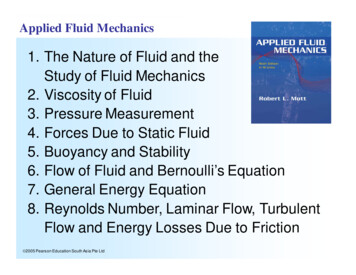
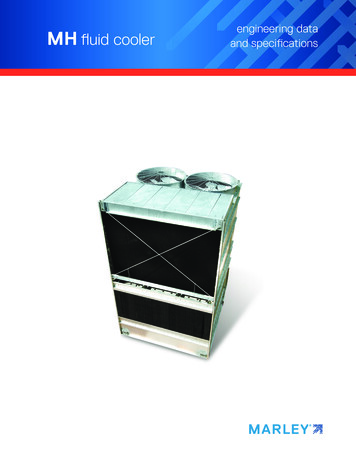
MH Fluid Cooler — Engineering Data: Support6AIR INLETFACEAIR INLETFACEAIR INLETFACECL ANCHOR BOLTANCHOR BOLT CLANCHOR BOLT CL CL ANCHOR BOLTDANCHOR BOLT CL CL ANCHOR BOLTD3 1/2"SINGLE-FLOW MODELS3 1/2"DOUBLE-FLOW MODELSMaximumDeflectionModelD 8"MHF711122'-9 3 4"1 8"MHF711324'-9 3 F710711'-9"1MHF710911'-9"1MaximumDeflection 2" 2" 8" 2" 2"Use this data for preliminary layouts only.Obtain detailed support drawings from yourMarley sales representative.Primary support consists of parallel I-beamsrunning the full length of the unit.
MH Fluid Cooler — Engineering Data: Freeze PreventionFLUID COOLER COILFLUID COOLING RECIRCULATING WATERWhen the ambient temperature falls below 32 F, heatloss from the coil be substantial even without recirculatingwater flowing over the coil. The process fluid, without anapplied heat load, may be prone to freezing. There are variousmethods to protect against coil freezing.When the ambient air temperature falls below 32 F, therecirculating water within the fluid cooler can freeze. MarleyTechnical Report #H-003 “Cooling Towers and FreezingWeather” describes how to prevent freezing during operation.Ask your Marley sales representative for a copy or downloada copy at spxcooling.com.Ethylene and propylene glycol solutions are the bestmeans to protect against coil freezing and are recommendedfor most installations. The appropriate concentration ofethylene or propylene glycol should be determined based onthe required protection from low ambient temperatures.If the use of an industrial antifreeze solution is notcompatible with the system, another accepted method ofpreventing coil freezing is to maintain a sufficient flow rateand heat load on the process fluid. The fluid exiting the coilmust be maintained at or above 45 F at the full process flowrate. If the process load does not yield such a heat load, itmay be necessary to apply a supplementary heat load to theprocess fluid.Draining galvanized steel coils is not considered to be anacceptable means of protection against freezing. Introducingair to the inside of the heat exchanger coil will promotecorrosion. In an emergency, this alternative can be usedin the event that the process fluid drops below 45 F, theambient temperature is below freezing and the coils are notprotected with industrial antifreeze. Copper coils and series300 stainless steel coils may be drained as necessary withoutsignificantly increasing corrosion risk.Cycling of the recirculating water pumps to controlprocess flow temperatures must be approached with caution.Frequent cycling of the recirculating water pump may leadto an excessive scale buildup resulting in a decrease inefficiency.During shutdown, water collects in the basin and mayfreeze solid. You can prevent freezing by adding heat to thewater left in the basin—or, you can drain the tower and allexposed pipework at shutdown.ELECTRIC BASIN HEATERSAn automatic basin water heater system, consisting of thefollowing components: Stainless steel electric immersion heater(s).Threaded couplings are provided in the side ofthe collection basin. NEMA 4 enclosure containing:Magnetic contactor to energize heater.Transformer to convert power supply to 24 voltsfor control circuit.Solid state circuit board for temperature andlow-water cutoff.The enclosure may be mounted on the side of thefluid cooler. Control probe in the collection basin to monitorwater temperature and level.The basin heater option is only for freeze protection of therecirculation water in collection basin. The basin heater optiondoes not protect the coil during freezing weather.Heater components are normally shipped separately forinstallation by others.INDOOR STORAGE TANKCAUTIONFreezing ambient conditions could cause significantdamage to the heat exchanger coil of the MH FluidCooler. To avoid possible damage, it is imperative toprovide for adequate freeze protection.With this type of system, water flows from an indoor tankand back to the tower where it is cooled and recirculated. Thewater flows by gravity from the fluid cooler to the tank locatedin a heated space. At shutdown, all exposed water drains intothe tank where it is safe from freezing.The amount of water needed to successfully operate thesystem depends on the fluid cooler size on volume of watercontained in the piping system to and from the tower. Youmust select a tank large enough to contain those combinedvolumes—plus a level sufficient to maintain a flooded suctionon your pump. Control makeup water according to the levelwhere the tank stabilizes during operation.7
MH Fluid Cooler — Engineering Data: Water QualitySYSTEM CLEANLINESSWATER TREATMENTThe MH Fluid Cooler can be a very effective air washer.Atmospheric dust able to pass through the relatively smalllouver openings will enter the recirculating water system.Increased concentrations can intensify systems maintenanceby clogging screens and strainers—and smaller particulatescan coat system heat transfer surfaces. In areas of low flowvelocity—such as the collection basin—sedimentary depositscan provide a breeding ground for bacteria.To control the buildup of dissolved solids resulting fromwater evaporation, as well as airborne impurities and biologicalcontaminants including Legionella, an effective consistentwater treatment program is required. Simple blowdown maybe adequate to control corrosion and scale, but biologicalcontamination can only be controlled with biocides.In areas prone to dust and sedimentation, you shouldconsider installing some means for keeping the collectionbasin clean. Typical devices include side stream filters and avariety of filtration media.BLOWDOWNBlowdown or Bleedoff is the continuous removal of asmall portion of the water from the open recirculating system.Blowdown is used to prevent the dissolved solids fromconcentrating to the point where they will form scale. Theamount of blowdown required depends on the cooling range—the difference between the hot and cold water temperaturesof the closed circuit— and the composition of the makeupwater. The MH Fluid Cooler is equipped with a blowdownline with metering valve connected directly to the overflow.Specific blowdown adjustment instructions and additionalblowdown information can be found in the MH Fluid CoolerUser Manual.CAUTIONThe fluid cooler must be located at suchdistance and direction to avoid the possibilityof contaminated discharge air being drawninto building fresh air intake ducts. Thepurchaser should obtain the services of aLicensed Professional Engineer or RegisteredArchitect to certify that the location of the fluidcooler is in compliance with applicable airpollution, fire and clean air codes.An acceptable water treatment program must becompatible with the variety of materials incorporated in a fluidcooler—ideally the pH of the recirculating water should fallbetween 6.5 and 9.0. Batch feeding of the chemicals directlyinto the fluid cooler is not a good practice since localizeddamage to the fluid cooler is possible. Specific startupinstructions and additional water quality recommendationscan be found in the MH Fluid Cooler User Manual whichaccompanies the fluid cooler and also is available from yourlocal Marley sales representative.8
MH Fluid Cooler — Specifications: BaseSpecifications1.0Base:1.1Provide an induced-draft, crossflow-type,factory assembled, galvanized steel,closed circuit fluid cooler. Unit shall consist of cell(s), as shown on plans.The limiting overall dimensions of thefluid cooler shall be wide,long, and high to the top of thefan guard. Total operating horsepower ofall fans shall not exceed hp. Fluidcooler shall be similar and equal in allrespects to Marley Model .2.0Thermal Performance:2.1Water as the heat transfer fluid.The fluid cooler shall be capable ofcooling gpm of water from F to F at a design entering airwet-bulb temperature of F. Coilpressure drop shall not exceedpsi. The thermal performance rating shallbe Certified by the Cooling TechnologyInstitute and Eurovent.2.1Aqueous glycol solution as the heattransfer fluid.The fluid cooler shall be capable of cooling gpm of % by volumeethylene/propylene glycol solution from F to F at a design entering air wet-bulb temperature of F. Coil pressure drop shall not exceedpsi. The thermal performancerating shall be Certified by the CoolingTechnology Institute and Eurovent.2.2The closed circuit cooling fluid coolershall be capable of a minimumgpm/hp efficiency per ASHRAEStandard 90.1.2.3Heat loss from the fluid cooler shall belimited to Btu/h for the standardfluid cooler/fluid cooler with positive closure dampers/fluid cooler with positiveclosure dampers and insulation, based on50 F inlet fluid temperature and -10 Fambient temperature with 45 mph windand fan(s) and pump(s) off.9Specification Value Your specification base establishes the type, configuration, base material, andphysical limitations of the fluid cooler to be quoted. During the planning and layout stages of your project, you will have focused your attention on a fluid coolerselection that fits your space allotment, and whose power usage is acceptable.Limitations on physical size and total operating horsepower avoid the introduction of unforeseen operational and site-related influences. Specifying the number of cells, and the maximum fan hp/cell will work to your advantage.The benefit of crossflow fluid coolers is that they are inherently easy to operate,access, and maintain. Unlike counterflow fluid coolers, crossflow fluid coolers have a spacious plenum between banks of fill for easy access to all of thetower’s internal components, and the water distribution system is adjacent tothe fan deck. C ertification means that the fluid cooler has been tested under operating conditions and found to perform as rated by the manufacturer under those circumstances. It assures the buyer that the tower is not intentionally or inadvertentlyundersized by the manufacturer. The MH Fluid Cooler has been tested and performance certified with water, ethylene glycol solutions up to 50% concentrationand propylene glycol solutions up to 50% concentration.The minimum efficiency per ASHRAE Standard 90.1-2010 for axial-fan closedcircuit cooling towers applied to comfort cooling is 14.0 gpm/hp at 102 F /90 F / 75 F, where hp is the sum of the fan motor nameplate power and theintegral spray pump motor nameplate power. If a greater efficiency is desired, ahigher ASHRAE Standard 90.1 gpm/hp can be specified. Each model’s ratingat ASHRAE Standard 90.1 conditions can be viewed in our online selectionsoftware at spxcooling.com/update.
MH Fluid Cooler — Specifications: BaseSpecifications3.0Performance Warranty:3.1CTI and Eurovent Certification notwithstanding, the fluid cooler manufacturershall guarantee that the fluid coolersupplied will meet the specified performance conditions when the fluid cooleris installed according to plans. If, becauseof a suspected thermal performance deficiency, the owner chooses to conduct anon-site thermal performance test underthe supervision of a qualified, disinterested third party in accordance with CTI,Eurovent or ASME standards during thefirst year of operation; and if the fluidcooler fails to perform within the limits oftest tolerance; then the fluid cooler manufacturer will pay for the cost of the testand will make such corrections as areappropriate and agreeable to the ownerto compensate for the performance deficiency.4.0Coil:4.1Coil(s) shall consist of fully welded boxheaders with serpentine tube circuits andshall be hot-dip galvanized after fabrication. The coil(s) shall be designed for freedrainages of fluid at shutdown. Minimumdesign operating pressure shall be 150psi. Coil(s) shall be warranted against anyfailure caused by defects in materials andworkmanship for a period of eighteen(18) months from the date of shipment.5.0Design Loading:5.1The structure and anchorage shall bedesigned to withstand a wind loadof 50 psf while operating, based onInternational Building Code ASCE7-10,as well as a .3g seismic load. The fluidcooler shall be designed to withstandshipping and hoisting loads of 2g horizontal or 3g vertical. The fan deck and hotwater basin covers on doubleflow modelsshall be designed for 50 psf live load ora 200 lb concentrated load. Guardrails,where specified, shall be capable of withstanding a 200 lb concentrated live loadin any direction, and shall be designed inaccordance with OSHA guidelines.10Specification Value However, certification alone is not sufficient to assure you that the fluid coolerwill perform satisfactorily in your situation. Certification is established under relatively controlled conditions, and fluid coolers seldom operate under such idealcircumstances. They are affected by nearby structures, machinery, enclosures,effluent from other sources, etc. Responsible and knowledgeable bidders willtake such site-specific effects into consideration in selecting the fluid cooler—but the specifier must insist by the written specification that the designer/manufacturer guarantee this “real world” performance. Any reluctance on the part ofthe bidder should cause you some concern. T he MH Fluid Cooler coil is suitable for cooling water, oils, andother fluids compatible with carbonsteel in a closed, pressurized system. Eachcoil is constructed of all-prime surface, continuous steel tubing, formed into a serpentine shape andwelded into an assembly. The complete assembly is thenhot-dip galvanized after fabrication. Tubes are sloped to provide free drainagewhen vented. The indicated design values are the minimum allowables under accepteddesign standards. They give you assurance that the fluid cooler can be shipped,handled, hoisted—and ultimately operated in a normal fluid cooler environment.Most MH Fluid Cooler models will withstand significantly higher wind and seismic loads. If your geographic location dictates higher wind load or seismic loadvalues, please make the appropriate changes, after discussion with your Marleysales representative.
MH Fluid Cooler — Specifications: BaseSpecifications11Specification Value6.0Construction:6.1Except where otherwise specified, allcomponents of the fluid cooler shall befabricated of heavy-gauge steel, protected against corrosion by G-235 galvanizing. After passivation of the galvanizedsteel (8 weeks at pH 7-8, and calciumhardness and alkalinity at 100-300 ppmeach), the fluid cooler shall be capable ofwithstanding water having a pH of 6.5 to9.0; a chloride content up to 500 ppm asNaCl (300 ppm as Cl-); a sulfate content(as SO4) up to 250 ppm; a calcium content (as CaCO3) up to 500 ppm; silica(as SiO2) up to 150 ppm. The circulatingwater shall contain no oil, grease, fattyacids, or organic solvents. In the history of fluid coolers, no other coating for carbon steel has exhibitedthe success and longevity of galvanization in exposure to the normal fluid coolerwater quality defined at left. No paints or electrostatically-applied coatings, however exotic they may be, can approach galvanization's history of success.If extended longevity of the fluid cooler is required—or unusually harsh operatingconditions are expected—consider specifying stainless steel as either the baseconstruction material, or the material utilized for specific components of yourchoice. See Stainless Steel Options on page 14.6.2The specifications, as written, are intendedto indicate those materials that will becapable of withstanding the above waterquality in continuing service, as well as theloads described in paragraph 6.1. They areto be regarded as minimum requirements.Where component materials unique toindividual fluid cooler designs are notspecified, the manufacturers shall takethe above water quality and load carryingcapabilities into account in the selection oftheir materials of manufacture.7.0Mechanical Equipment:7.1MHF7101, MHF7103, MHF7105,MHF7107 and MHF7109 - Fan(s) shallbe driven through a one-piece multigroove, solid back V-type belt. Bearingsand fan shaft shall be contained in a caststeel housing to insure proper fan shaftalignment, pillow block bearings are notallowed. Bearings shall be rated at anL10A service life of 40,000 hours orgreater Axial-flow fans require only half the operating hp of blower-type fans. The Marleydrive system features all-aluminum sheaves, matched belts, and long-life bearings for dependable service.MHF7111 and MHF7113 – Fan(s) shallbe heavy duty, high efficiency, low soundaxial design, incorporating aluminum alloyblades attached to galvanized steel hubswith U-bolts. Blades shall be individuallyadjustable. Fan(s) shall be driven througha right angle, industrial duty, oil lubricated,geared speed reducer that requires nooil changes for the first five (5) years ofoperation. All gearbox bearings shall berated at an L10A service life of 100,000 The exclusive Marley System5 Geareducer requires no oil changes for fiveyears, offering you unmatched reliability and low maintenance.7.1 To reduce cost, some manufacturers may use TEAO motors, whose only sourceof cooling is the flow of air produced by the fluid cooler fan. They are sometimesapplied at horsepowers significantly beyond their nameplate rating.Unless otherwise specified, motor speed will be 1800 RPM, 60 Hertz on standard models.
MH Fluid Cooler — Specifications: BaseSpecifications12Specification Valuehours or greater and the gear sets shallhave AGMA Quality Class of 9 or greater.The gearbox shall include any modifications to enable operation down to 10% offull speed.7.2Fan motor(s) shall be hp maximum,NEMA Premium Efficiency TEFC, 1.15service factor, variable torque, inverterduty and specially insulated for coolingfluid cooler duty (Class F). Speed andelectrical characteristics shall beRPM, single-winding, 3 phase, 60 hertz,volts. Motors shall operate in theshaft-vertical position for belt-drivefluid coolers and in the shaft-horizontalposition for gear drive fluid coolers.Nameplate power shall not be exceededat design operation. TEAO motors shallnot be acceptable.7.3The fan and fan drive assembly for eachcell shall be supported by a rigid, galvanized steel structural support that resistsmisalignment. The mechanical equipmentassembly shall be warranted againstany failure caused by defects in materials and workmanship for no less thanfive (5) years following the date of fluidcooler shipment. This warranty shall coverthe fan(s), premium efficiency motor(s),geared speed reducer(s), drive shaft(s)and couplings, and the mechanical equipment support. Bearing assemblies andV-belts shall be warranted for 18 months.8.0Fill, Louvers and Drift Eliminators:8.1Fill shall be film-type, thermoformed ofheavy duty PVC, with louvers and eliminators formed integrally in each fill sheet.Fill shall be suspended from galvanizedstructural tubing supported from the fluidcooler structure. The air inlet face(s) ofthe fluid cooler shall be free of watersplash out.8.2Coil air-inlet louvers shall be a minimumof 0'-5" air travel, triple-pass PVC to limitwater splash out and prevent direct sunlight from entering the collection basin.PVC louvers shall be easily removable foraccess to the coil(s). Louvers with lessthan three changes in air direction areunacceptable. The value of a 5 year mechanical equipment warranty speaks for itself. Louvers integral with the fill keep the flowing water within the confines of the fill.The separate external louvers used by others permit water to escape the fill andform ice or produce an unsightly situation adjacent to the tower. If you plan touse your tower in the wintertime, particularly for free cooling, integral louvers willput your operating concerns to rest.
MH Fluid Cooler — Specifications: BaseSpecifications8.3Drift eliminators shall be heavy duty PVCwith a minimum of three changes in airdirection, and shall limit drift losses to0.005% or less of the design recirculatingwater flow rate.9.0Distribution Basins:9.1An open basin above the fill with removable interchangeable polypropylenenozzles installed in the floor of the basinshall provide full coverage of the fill bygravity flow. Basin shall be installed andsealed at the factory and assembled withbolted connections. Tap screws shall notbe allowed. The basins shall be equippedwith removable, galvanized steel covers capable of withstanding the loadsdescribed in paragraph 5.1. The waterdistribution system shall be accessibleand maintainable during fan and wateroperation.9.2A redistribution basin below the fill withpolypropylene nozzles installed in the floorof the basin shall provide full coverage ofthe coil at a flow rate sufficient to ensurecomplete wetting of the coil duringoperation. The basin shall be installed andsealed at the factory and assembled withbolted connections. Tap screws shall notbe allowed.10.0Casing, Fan Deck and Fan Guard:10.1The casing and fan deck shall be heavygauge G-235 galvanized steel panels.The top of the fan cylinder(s) shall beequipped with a conical, non-sagging,removable fan guard, fabricated of welded5/16" and 7 gauge rods and hot-dip galvanized after fabrication.11.0Access:11.1A large galvanized steel, rectangularaccess door shall be located on bothendwalls for entry into the cold waterbasin and fan plenum area. Access doorsshall be a minimum of 24" wide and 42"tall and shall be operable from inside aswell as outside of the fluid cooler.13Specification Value Drift rate varies with design water loading and air rate, as well as drift eliminator depth and number of directionalchange
The Marley MH Fluid Cooler is one of the most efficient closed-circuit heat rejection products on the market—and your best choice for industrial and HVAC applications. By keeping the process fluid in a clean, closed loop, and combining the function of a cooling tower and heat exchanger into one system, the MH Fluid Cooler can