Transcription
Air Cooler ManualCustomized air cooler
Index1.Preface2.Refrigeration - introduction and key definitions3.Conceptual knowledge of air cooler4.Types of ammonia refrigeration systems5.Air cooler design fundamentals6.Air cooler selection basis – DT1 or DTM?7.Air cooler design & selection guidelines8.Air side fundamentals and guidelines9.Defrosting methods10. Air cooler trouble-shooting guidelines11. Sample project specification sheet
PrefaceIn vapour compression refrigeration systems the majorcomponents are compressor, evaporator and condenserbesides expansion device. Although compressor is called asheart of the system, since it is the only moving componentand most expensive one, the stored products do notrecognize as to what is the Refrigeration tonnage or what isthe type of compressor, condenser etc. The preservation ofthe product quality is predominantly dependent on theevaporator performance and the high side of the systembecomes the back end or supporting part since it is the aircooler which is directly exposed to the stored commodity.The evaporator or air cooler used for preservation of foodstherefore plays the most important part since it circulates theair in the cold room at a temperature and humidity required tobe maintained for a particular product to be stored. Tomaintain uniform temperature in the room and of the product,the air circulation distribution is also very important.The air cooler selection for each application is unique whichwould meet the expected requirements. The selection of aircooler for high humidity storages for products such asvegetables, fruits is much different than air cooler selectionfor low humidity product storages such as onions, seedgrains etc. The requirement of blast freezers or precoolingrequires altogether different approach while selecting the aircoolers.In view of large range of evaporators available in the markethaving different coil geometries, material of construction,defrosting methods, circuit options, there is no uniformity intechnical specifications of air coolers offered by variousmanufacturers/suppliers. Many important factors arepresented in a manner which makes the “real” comparisondifficult. Often the selections are based manufacturersoftware & the comparison of different air coolers offeredmakes it difficult for the buyer to decide as to which is the rightcooler for his requirement.This guide book is intended to provide refrigeration plantdesigners, operators, consultants and end users theinformation needed to make appropriate selection and toserve as a desk reference.The information presented deals with ammonia air coolers forcold storages, and freezer rooms, blast freezers, processinghalls, pre-cooling chambers or any other related end uses forpreservation of food.The document has been prepared and information compiledbased on various papers published, text books, ASHRAEvolumes, IIAR publications to meet the requirements ofengineers, contractors, dealers, actual users etc. withoutgoing in to too much theoretical aspects so that it is easy forthe reader to absorb the information without missing theimportant aspects while selecting the air coolers for particularapplication he has in mind.The guidebook is prepared by Mr. Ramesh Paranjpey ASHRAE Fellow Life member and Alfa Laval India team tomake the decision makers and other concerned personsaware of the different aspects which need to be consideredwhile comparing air coolers available in the market.We are sure that the information presented would lead tomore appropriate selection of forced circulation air coolersand successful commodity storage application leading tomaintain top class product quality without deterioration orweight loss while retaining all the nutritional values.
Refrigeration, Introductionand key definitionsIntroductionRefrigeration is essential and absolute must for foodpreservation. Heat removal from product via cooling orfreezing of product prevents, or slows down microbial andchemical changes in the product. Temperature and humidityas well as air distribution within refrigerated spaces are majorconsiderations in food preservation processes such as postharvest cooling, blast freezing, and product processing orproduct storage. The timing associated with producttemperature pull down, heat removal, is critical to the finalcondition and market life.The evaporator is the crucial component within anyrefrigeration system being responsible for removal of the heatfrom product and maintaining uniform temperature and airdistribution to ensure no stagnant area exist or noappreciable weight loss takes placeDefinitions:1. Forced-Air Circulation Unit Coolers (UnitCoolers). A factory-made assembly, including fans for forced aircirculation and coil by which heat is transferred from air torefrigerant. These may also be referred to as Air Coolers,Cooling Units, Air Units, unit coolers, product coolers orEvaporators.2. Liquid Overfeed Unit Cooler. A Unit Cooler in which the refrigerant liquid is supplied at aRecirculation Rate greater than one. It can be gravity floodedor forced feed pump circulation system design.3. Gross Total Cooling Effect (Cooling Capacity).The heat absorbed by the refrigerant, W(Btu/h) . This is thesum of the Net Total Cooling Effect and the heat equivalent ofthe energy required to operate the Unit Cooler. This includesboth sensible and latent cooling.4. Net Total Cooling Effect. The refrigeration capacity available for space and productcooling, W (Btu/h). It is equal to the Gross Total Cooling Effectless the heat equivalent of energy required to operate theUnit Cooler. This includes both sensible and latent cooling.5.Overfeed Ratio. The mass ratio of liquid to vapor at the outlet of the LiquidOverfeed Unit Cooler. This may also be referred to asoverfeed rate.6.Recirculation rate(Overfeed rate 1) or The mass ratio of liquid circulated to theamount of liquid vaporized7.Refrigerant Saturation TemperatureRefrigerant temperature at the Unit Cooler inlet or outletdetermined either by measuring the temperature at the outletof the two-phase refrigerant flow, for a Liquid Overfeed UnitCooler, or by measuring refrigerant pressure and determiningthe corresponding temperature from referencethermodynamic tables or equations for the refrigerant.8.Temperature Difference (TD)The difference between the dry-bulb temperature of the airentering the Unit Cooler and the Refrigerant SaturationTemperature at the unit cooler outlet.9.Enthalpy Difference (HD).The difference between the enthalpy of the air entering theUnit Cooler and the calculated enthalpy of saturated air at theRefrigerant Saturation Temperature at the Unit Cooler outlet,J/kg (Btu/lb).10.Rated Power.For single phase motors, total fan motor input power, W orkW.For poly phase motors, individual fan motor output power,kW (hp).11.Standard Air Conditions. Dry air at 21 ºC (70 ºF) andabsolute pressure 101.325kPa(29.92 in Hg). Under theseconditions, dry air has a mass density of 1.2 kg/m3 (0.075lb/ft3).
1.What is Air Cooler-Evaporator:Air cooling ammonia Industrial evaporators are refrigerant toair heat exchangers widely used in industrial refrigerationapplications. They are also known as forced circulation aircoolers or air cooling evaporators, or other names asindicated n the definition 12.What is the principal of operation:These are the heat exchangers using tubes that carryammonia refrigerant inside the tubes. The tubes areexternally provided with fins to increase outside heattransfer area. Liquid refrigerant evaporates inside the tubesas it absorbs heat from air flowing over & coming incontact with outside surface of fins and tubes. Individualtubes of heat exchanger are arranged in multiple rows ofparallel circuits to achieve increased thermal performance.The external cold fin surface cools the air coming incontact is circulated by fans at a designed velocity.3.What are the fields of applications:The ammonia refrigeration air coolers are widely used tocool and circulate air in cold storages, warehouses andother food processing facilities.4.What is the Function of Air Cooler:Heat removal from the product via cooling or freezing ofthe product prevents, or retards, microbial and chemicalchanges in the product. In today's world product quality isparamount for the end user and vital to realized revenue.Whether this is related to post harvest cooling, blastfreezing, process cooling or product storage many factorswill ultimately determine the quality of the product beingrefrigerated. Temperature and air distribution withinrefrigerated warehouses are major considerations. Thetiming associated with product temperature pull down,heat removal, is critical to the final condition, and marketlife, of the respective product. Temperature deviations of2 F (1.1K) to 3 F (1.6K) above or below the desired setpoint are often too great and could be harmful to theproduct. Air distribution within the facility should beconstant throughout and care should be exercised toensure no stagnant areas exist within the refrigeratedspace.5.The evaporator/s is the crucial component within anyrefrigeration system and performs all these functions. Theair coolers are widely used in commercial and industrialrefrigeration applications in various segments of foodpreservation to cool and circulate air in cold storagewarehouses.a. In Fruit and vegetable and other positive temperaturecold storages the function of air cooler is to cool theproduct from ambient temperature to desired temperatureand humidity levels in prescribed time limit as also to storethe product for a expected duration in the cold storageswithout deteriorating product quality or weight loss. Thecooling unit is not supposed to improve the quality ofincoming product but to maintain the same qualitythroughout its storage life retaining the quality which wasthere at the time of loading.b. The unit coolers can be used in processing halls,grading and sorting halls, ante rooms etc.c. The air coolers are used for negative temperature forstoring frozen products such as meat ,fish, vegetablesgenerally at -200Cd. The unit coolers are used for Ice cream storage atmuch lower temperature around -300Ce. The unit coolers are used in food freezing applicationssuch as blast freezers, tunnel freezers, spiral freezers, IQF, and many other products generally at -400Cf. The unit coolers are also used in variety of otherapplications
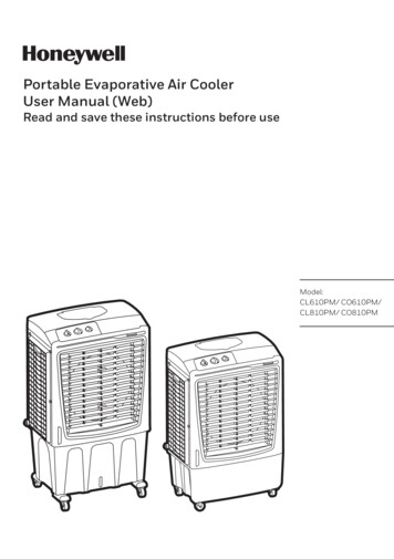
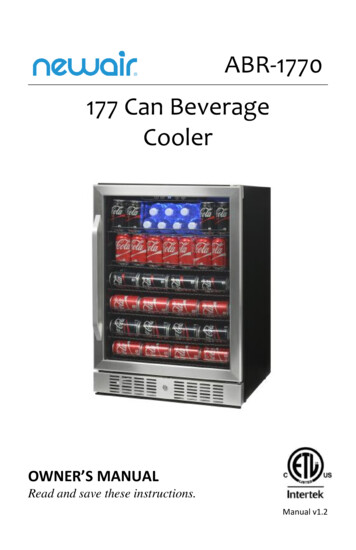
Conceptual knowledgeof air coolerThese are the heat exchangers using tubes that carryammonia refrigerant inside the tubes. The tubes areexternally provided with fins to increase outside heat transferarea. Liquid refrigerant evaporates inside the tubes as itabsorbs heat from air flowing over & coming in contact withoutside surface of fins and tubes. Individual tubes of heatexchanger are arranged in multiple rows of parallel circuits toachieve increased thermal performance. The external coldfin surface cools the air coming in contact, which is circulatedby fans at a designed velocity.23 4 5 678910removal, is critical to the final condition, and market life, of therespective product. Temperature deviations of 1.1 to 1.6Kabove or below the desired set point are often too great andcould be harmful to the product. Air distribution within thefacility should be constant throughout and care should beexercised to ensure no stagnant areas exist within therefrigerated space.Field of applications of Air cooler :The air coolers are widely used in commercial and industrialrefrigeration applications in various segments of foodpreservation to cool and circulate air in cold storagewarehouses.The following are few examples of applicator of an Air Cooler11)2)3)4)5)6)7)8)9)10)Drip trayEnd cover (left/right identical)Mounting feetFan cowl/ringFan unit completeFan ring heaterSafety/repair switchElectric defrost heaterAirsock ringConnection boxFig. 1Expectations from a good Air Cooler:Heat removal from the product via cooling or freezing of theproduct prevents, or retards, microbial and chemicalchanges in the product. In today's world product quality isparamount for the end user and vital to realized revenue.Whether this is related to post harvest cooling, blast freezing,process cooling or product storage many factors willultimately determine the quality of the product beingrefrigerated. Temperature and air distribution withinrefrigerated warehouses are major considerations. Thetiming associated with product temperature pull down, heata. In Fruit and vegetable and other positive temperature coldstorages the function of air cooler is to cool the product fromambient temperature to desired temperature and humiditylevels in prescribed time limit as also to store the product foran expected duration in the c o l d s t o r a g e s w i t h o u tdeteriorating product quality or weight loss. The cooling unitis not supposed to improve the quality of incoming p r o d u c tbut to maintain the same quality throughout its storage liferetaining the quality during the time of loading.b. The air coolers can be used in processinghalls, grading and sorting halls, ante rooms etc.c. The air coolers are used for negative temperature forstoring frozen products such as meat, fish, processedvegetables generally at -200Cd. The unit coolers are used for Ice cream storage at muchlower temperature around -300Ce. The unit coolers are used in food freezing applicationssuch as blast freezers, tunnel freezers, spiral freezers, IQF ,and many other products generally at -400Cf. The unit coolers are also used in variety of otherapplications
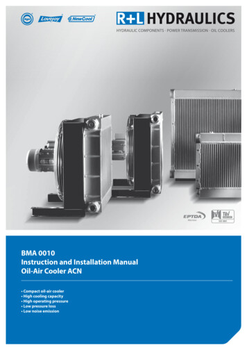
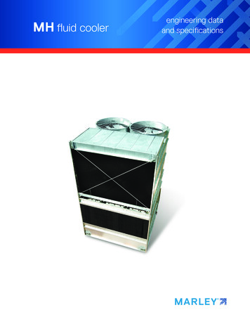
Types of ammoniarefrigeration systemsvery small requirements such as process, grading/sortinghalls etc.1.What are the standard methods of supplyingammonia refrigerant to the evaporatora. Direct Expansionb. Gravity Floodedc. Pump circulation-overfeed2.Describe operation of direct expansion(DX)system:Expansion ValueFinsTubeLiquidRefrigerantThe direct expansion air coolers in ammonia are seldomused due to high latent heat of ammonia and the flow rateto achieve a given refrigerant capacity will be too low with¾ or 1” tubes. Another important issue is to ensure oilreturn to compressor with such low ammonia velocitiessince ammonia and oil being not miscible the oil wouldtend to remain in the coil endangering the compressoroperation. The use of ammonia miscible oils has enableduse of Direct Expansion evaporators in above freezingtemperature applications in smaller capacities using tubesless than 5/8” diameter.3. Describe operation of Gravity FloodedEvaporator systems:TemperatureSensing BulbFinsSuperheatedRefrigerantVaporSungeDrum(a) Direct Expansion Air Coil - Fig 1The high pressure liquid ammonia is expanded in theexpansion valve and mixture of low temperature andpressure liquid plus vapour mixture enters the tubes. Themixture is having predominant part of liquid and somequantity of flash gas. In the evaporator tubes the liquidammonia gradually evaporates as it travels to wardssuction header by absorbing heat from air coming incontact with tubes and fins and in turn cools the air. Therefrigerant leaving the evaporator is superheated to theextend based on superheat setting of expansion valvewhich is normally around 50 C. the refrigerant liquid vapourmixture travels from inlet to outlet when liquid componentis reduced and vapour component increases and at theoutlet one gets only superheated vapour. The travel ofmixture is only in one direction from inlet to outlet and thereis no recirculation as the vapour coming out of evaporatordirectly goes to compressor suction and passes troughentire system before it enters the evaporator again.The direct expansion ammonia coolers are used generallyfor positive or above freezing temperature applications forRefrigerant VaporTubeLiquidRefrigerantFloat ControlValueLiquidLog(b) Flooded Air Control - Fig 2The refrigerant in the evaporator is mostly liquid (flooded)from the beginning to the end of the process. The floodedevaporator provides for recirculation of refrigerant within theevaporator by the addition of a accumulator/surge drum.The liquid refrigerant enters the accumulator drum throughthe metering device and gravity causes it to flow down tothe bottom tube.The entire coil surface is in contact with wet refrigerantunder any load condition. This design produces excellentheat transfer. The vapour produced in the evaporator isseparated from liquid in surge drum. The liquid is recirculated through the evaporator again, while the vapouris sucked by the suction action of compressor.
The flooded evaporator regulates refrigerant flow by a floatdevice, which is designed to maintain a predeterminedliquid level in surge drum. The vapour leaving the surgedrum is saturated and not superheated as in case of DXevaporator. Flooded evaporators are therefore moreefficient as entire coil surface is exposed to wet refrigerantand therefore the heat transfer is better. In dry evaporatorspart of coil area is wasted in superheating gas and the coilsurface is always in contact with part liquid and part gas.Although these are more efficient compared to DXevaporators, careful design has to be made to ensureproper liquid/vapour separation in surge drum, it’s locationto ensure that liquid is not carried over to the compressor.The design of surge drum, its various connections andvelocity of refrigerant has to be taken care of.Ammonia refrigeration systems normally work on floodedoperation principle.4. Describe functioning of Pump circulation(overfeed) systems:recirculation/overfeed systems are preferred. Normally formore than 3 to 5 evaporators & located considerably awayfrom machine room, liquid recirculation is the best option.Properly designed flooded evaporators and evaporatorsoperating with liquid recirculation operate with equaleffectiveness. What is then is the basis for choosingbetween flooded coils and a liquid recirculation systemserving multiple coils?”The dominant refrigeration system for intermediate to largestorage facilities is the liquid overfeed ammoniarefrigeration system. This system is suitable for low andmedium temperature cold storage.”The use of liquid overfeeds system is thereforeadvantageous:1.When there are more than 4 to 6 evaporators of largercapacity in medium or large cold size cold storages.2.Plant room is located far away from the processing areawhere evaporators are located involving lengthy refrigerantdistribution pipe work.3.Special evaporators like spiral freezers/IQF or platefreezers are involved.4.The requirement is for medium or low temperaturecommodity storage.5.Hot gas defrost systems to be usedPumped System - Fig 3In liquid overfeed systems the refrigerant liquid coming outof receiver is expanded to the requiredpressure/temperature and this liquid is stored in lowpressure receiver. It is then pumped in the variousoperating evaporators, like product coolers, blast freezersor plate freezers. It thus forms an independent low sidecircuit. The compressor sucks the vapour from this lowpressure receiver and the cycle repeats.The overfeed means much more liquid is fed to evaporatorthan the liquid actually vaporizes. Excess liquid is calledoverfeed, which returns to low pressure side accumulatoror known as L.P. receiver. Thus the mass flow rate handledby compressor is less than the mass flow rate circulated inthe evaporator.As the number of evaporators increase and as thetemperature requirement gets lower and lower, liquid
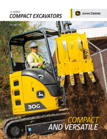
Air cooler design fundamentals1.Define what is Primary surface and Secondary surface:Evaporator coils are constructed using tubes and fins bonded to the tubes. Fins are referred to as 'secondary surfaceA0'and tubes are referred as 'primary surface A’I2.Which surface is more effective:For purpose of calculating evaporator performance, primary surface is more effective since the liquid ammonia at lowesttemperature is inside the tube and heat transfer rate is highest because of higher 'TD' between air and refrigerant. Theprimary surface is therefore considered as 100% effective in its contribution to its contribution to the total heat transfersurface area.The secondary surface has a surface effectiveness less than 100% due to the change in surface temperature from the rootto the tip of the finHow the effective heat transfer area required is then calculated?SdSfindTShdfinLfindhFig 4Where:ShSdSfinrdTdhLfinnisisisisFin height pert tubeFin depth per tubeFin Spacingratio of enhanced fin surface area to flat, claimed by applicant(to be supported by drawing and calculations if grater than 1)is Tube outside diameteris Diameter of other holes in fin e.g. heater holesis Finned lengthis Number of other holes (dh) per tube holes(dT)(Unit)(mm)(mm)(mm)(mm)(m)The Surface area per tube, per meter - finned length is: SA (2/Sfin/1000) x r x (Sh x Sd-p/4 x (dT2 n x dh2)) p x dT/1000The Total Surface Area(m2)TSA SA x Lfin x Number of Tubes
There are two important equations which cover theselectiona. The standard equation for heat flow isQ (A0 U LMTD)Where ‘Q’ Total heat transfer rate‘U’ overall Heat Transfer Co-efficient‘LMTD’ or DT logarithmic Mean Temperature DifferenceThis equation helps in determining the required heattransfer area for the cooling coil and onceselected/manufactured and supplied cannot be altered atsite.b. The second equation isQsensible m x Cp (T air entering-T air leaving)Orkgm3qs x ρ ( air density) x Cp (T air entering-T air leaving)m3hrOrq total kgm3x ρ ( air density) x Cp (h1 air entering-h2 air leaving)m3hrh1 Enthalpy of air entering coilh2 enthalpy of air leaving coilengineer, while selecting the air coolers uses differentcombinations of DT and A0 to arrive at cost effective andappropriate solution of air cooler to suit particularcommodity storage requirements1. Air quantity2. Cold room temperature3. Air inlet temperature to coil4. Air out let temperature from coil5. Whether blow through or draw through design6. Saturated evaporating temperature at coil outlet7. Coil pressure drop8. Air side pressure drop9. Air throw10. Fan characteristic-static v/s head at operatingtemperature11. Fan power consumption at operating parameters andinstalled motor powerWe shall now analyze the first equation in more details fromthe manufacturer's perspectiveQ (A0 U ΔT)Q Total sensible heat to be transferred per unit time (kW)'U' is the overall heat transfer coefficient and is mostly thecharacteristic of coil based on its design and applicationengineer has a limited role in its selection.Cross sectional area of typical fin-This equation allows us to select required air quantity to becirculated in order to maintain uniform temperature insidethe cold room. The air quantity can be varied by changingthe fan speed or switching off one or more fans and thiswould alter the air cooler performance and the conditionsin the cold room.Factors under manufacturer's or designer'scontrolThe first equation has two parts, the first being 'U' value oroverall heat transfer coefficient and it is under the coildesigner's control. The coil designer has control overfollowing parameters1. Tube and fin material of construction2. Fin spacing3. Fin pattern-staggered or parallel4. Fin type –plain plate or any other pattern to increase finarea5. Fin thickness6. Tube diameter and thickness7. Circuiting8. Air and refrigerant flow pattern9. Coil GeometryFactors under Application Engineer's controlWhereas the application engineer has control over the coilsurface area 'A' to be selected and TD, i.e. roomtemperature and evaporating temperature. An applicationFig 5In the evaporator, the heat flows in series throughthree thermal resistances.1. From the room air to the outside surface of theevaporator or fins in case of finned coolers-Rf2. From the outside surface to the inside surface of theevaporator-Rm3. From the inside surface of the evaporator to therefrigerant-RrThe heat flow can be compared to electrical currentpassing through series of resistances as shown in thefig 3.Rf- Resistance to heat flow on air side and is dependenton air velocity, fin configuration and type of fins as well asits spacing.η- Fin efficiency- If the entire fin were at the sametemperature as the tube, the fin effectiveness would be
100%. However it is not the case and the temperatureincreases progressively as we move further away from thetube. All the air side area is therefore not 100%effective/efficient. The effectiveness of the fin is given bythe symbol 'η' and the value varies from 0.3 to 0.7 forcommercial coils depending upon fin material and finthickness and on type of fin.Rm – Resistance to heat flow due to metal conductivity andthickness of the tube x/kRr- Resistance to heat flow on the refrigerant side anddepends upon refrigerant used, its velocity and tubediameter.The overall heat transfer coefficient 'U' is sum of thereciprocal of all resistances and depends upon (a) the heatexchanger configuration (b) the ratio of primary tosecondary surface area(c) the air velocity, temperature,density (d) properties of refrigerant and its velocity (e) tubeand fin material (f) and fouling factors on either side.U 1(Rf Rm RT)The Heat flow can also be described as under1 Q A0 U (T1- T4)2 Q hf η A0 (T1- T2)3 Q kx Am (T2- T3)4 Q hr Ai (T3- T4)Wherehf is the heat transfer coefficient on the air side 1(W m-2 k-1)Rfhr is the heat transfer coefficient on refrigerant side 1(W m-2 k-1)Rrhm is the heat transfer coefficient of the tube 1(W m-2 k-1)Rmk is the conductivity of the material (W m-1 K-1)x is the thickness of tube -mA0 is the outside or fin area which is the tube externalarea in case of plain tubes or Secondary area-m2Ai is the inside area of the evaporator through which therefrigerant flows or Primary area-m2Equation 1 can be rearranged as - (T1- T4) QA0 U(T1 – T4) can also be expressed as [(T1-T2) (T2-T3) (T3-T4)]Substituting (T1 – T4), (T1-T2), (T2-T3) and (T3-T4)from equations 1, 2, 3 and 4 respectively, QQ Q QA0 Uhf η A0 kx Am hr Ai 11 A0 U hf η A0kx11 Am hr Ai 11 AA1 0 0xU hf η k AmAi h r 1 Rf R x A0 R x A0mrUηAmAiThe heat transfer coefficient ‘U’ should be as high aspossible, to make the evaporator compact and efficient,which means sum of the resistances mentioned aboveshould be as small as possible1. Looking at individual resistances, it means Rf should beas low as possible and fin efficiency ƞ should also be ashigh as possible. As the fin area increases fin efficiencyreduces since the area away from primary tube area is notas effective as area near the tube as mentioned above.2. Rr should be as low as possible3. A0/ Ai should be as low as possible.(Lessexternal secondary fin area A0 & more internalprimary area Ai)The above equations lead to very important conclusion thatthe coil which has more primary surface area and lesssecondary surface area will have highest heat transferefficiency.Definitions of Terms applied to air coila. Coil circuit: the route of the refrigerant from the time itenters a tube until it leavesb. Coil Depth: No of rows of tubes the air passes fromentrance to exit of the coilc. Face area: The cross-sectional area through whichthe air passes as it enters the coil, alternately it is also thefin height x fin widthd. Face Velocity: The volume rate of air flow divided bythe face areae. Header: A common pipe from which all circuits aresupplied refrigerant. Also a common pipe which gathers allrefrigerant leaving all the tube circuits.f. Pass: The flow of refrigerant through one straightsection of the circuitg. Prime Surface: The air side area of the tubes that isin contact with airh. Secondary surface: The surface area of both sidesof the fins in contact with the air.i.Return bends: or U bends are short sections ofcurved pipe to direct the refrigerant leaving one pass to theentrance of the next pass.
2. TubeThe heat transfer resistance on air side is say 0.11305m20C/W and on refrigerant side is 0.000833 m20C/Wwhich means air side resistance is 20 times that onrefrigerant side. It is important to note that the heat transfercoefficient on ammonia side is very high compared to airside and hence internally finned tubes are hardly used inammonia applications and therefore there is no need toincrease internal tube area by using groovedtubes.(Stoecker -175 page)Also the conductivity of material has comparatively lesscontribution in overall ‘U’ value or heat transfer coefficient.3.Fin Pattern-Square V/s Triangular3838503342Triangular pitchFig 7Advantages of Triangular fin Patterna. Better air side heat transfer coefficientb. The cooler manufacture becomes compactc. More turbulence across coil, lower fin temperatured. Higher secondary surface area for similar configurationBoth the fin thickness and fin material count. The heat shouldflow from the fin to the tube. The bigger the heat load, thebigger the heat resistance. So, the thinner the fin the greaterthe resistance will be. This effect combined with thetemperature flow in the fin is called fin efficiency. To get anidea of these effects, we would like refer to the diagrambelow.aI 1000W/m2Ks 8.0 mm353021. Material of construction for tubes and finsMaterials of construction for coil commonly consideredfor ammonia coolers area. Hot dip Galvanized Steel ( Stl/Zn)b. Stainless tubes with Aluminum fins (SS/Al)Decision to select material depends ona. Performanceb. Costc. Life of equipment-corrosion resistanced. Weighte. Ease of manufacture and weldingf. Ease of Site welding and repairs if requiredg. Strengthh. ReliabilityThe generally preferred industrial standard currently usedis Stainless steel tubes and aluminum finsSome manufacturers have also introduced aluminumtubes and aluminum fins for ammonia applicationse. Motor power requirement is lowerf. Longer cooling periods since infrequent defrostingg. Higher fin temperatures result in less dehydration, betterproduct qualityU (w/m K)We shall now look at and analyze factors which are underthe control of manufac
3. Conceptual knowledge of air cooler 4. Types of ammonia refrigeration systems 5. Air cooler design fundamentals 6. Air cooler selection basis - DT1 or DTM? 7. Air cooler design & selection guidelines 8. Air side fundamentals and guidelines 9. Defrosting methods 10. Air cooler trouble-shooting guidelines 11. Sample project specification sheet