Transcription
BMA 0010Instruction and Installation ManualOil-Air Cooler ACN Compact oil-air cooler High cooling capacity High operating pressure Low pressure loss Low noise emission
rl-hydraulics.comContents1.Basic information310.Important information for Ex-zones101.11.21.31.41.51.6Notes on this Instruction and Installation ManualAccuracy at time of going to pressIntended purposeWarranty and liabilityGuarantee and claimsContact information3333332.Safety410.1 Instruction manual supplement “Ex”10.2 Intended use10.2.1 Explosive atmosphere10.2.2 Instructions for use10.3 Industrial safety instructions10.4 Installation and assembly10.5 Checks, maintenance and repairs10.6 Testing10101010101011112.12.22.32.42.5Standards and directivesSafety instructions – graphic design and formSymbols usedWarning labelsGeneral safety instructions444443.Description/specification53.1 Sub-assemblies and options3.2 Nameplate / identification label554.6Installation of the oil-air cooler4.1 Installation site Installation in enclosed spaces Installation in the open Installation in dirty environments (spaces)4.2 Installation mode and position4.3 Electrical connections Terminal assignment4.4 Hydraulic connection666666665.Commissioning and start-up76.Operating the unit77.Maintenance77.1 Regular maintenance work7.2 Annual inspections:778.8Cleaning8.1 Cleaning the radiator8.2 Cleaning the inside of the cooler housing889.8Dismantling and assembling the sub-assemblies9.1 Dismantling the radiator9.2 Dismantling the electric motor and fan ACN 5 ACN 10 – ACN 60 ACN 70 – ACN 100899992
rl-hydraulics.com1. Basic information1.1 Notes on this Instruction and Installation manualPlease read the installation manual carefully before installing andoperating the ACN oil-air cooler; pay particular attention to thesafety instructions. The Instruction and Installation Manual is partof your product. Keep the Manual in a safe place in the vicinity ofthe ACN oil-air cooler. Property rights to this Instruction and Installation Manual remain with R L HYDRAULICS GmbH.1.2 Accuracy at time of going to pressWe reserve the right to make technical amendments and alterationsto reflect the current state of development. The ACN oil-air coolerdescribed here represents the current state of the art at the timethis Instruction and Installation Manual went to press.1.3 Intended purposeThe intended purpose of the ACN oil-air cooler is the cooling of hydraulic fluid (mineral oil, HFC (polyglycol 40%), HFD) in industrialplants and systems.1.4 Warranty and liabilityUnauthorised technical modifications to the ACN oil-air cooler areprohibited. Any such modifications are made entirely at the customer’s risk and exclude the manufacturer from any warrantyclaims or liability.1.5 Guarantee and claimsPlease contact your R L HYDRAULICS Partner in the event of any faultsor breakdowns. R L HYDRAULICS accepts no liability for any consequential loss or damage resulting from unauthorized repairs and/ormodifications carried out by the customer.1.6 KontaktdatenR L HYDRAULICS GmbHPostfach 1546D - 58775 WerdohlGermanyPhone: 49 (0) 2392 509-0Fax: 49 (0) 2392 509-509E-mail: info@rl-hydraulics.comwww. rl-hydraulics.com3
rl-hydraulics.com2. Safety2.1 Standards and directivesThe ACN oil-air cooler is ‘partly completed machinery’ under theterms of the EU Directive 2006/42/EC.By applying standard DIN EN ISO 12100:2011-03 during design andconstruction of the ACN oil-air cooler, the manufacturer has takeninto account the general requirements regarding safety and ergonomics.2.2 Safety instructions – graphic design and formDANGERWarns of an accident that will occur if instructions are notfollowed. The accident will cause serious, possibly lifethreatening injuries or death e.g. by coming into contactwith high-voltage electrical units.WARNINGWarns of an accident that can occur if instructions are notfollowed. The accident may cause serious, possibly lifethreatening injuries or death e.g. by coming into contactwith high-voltage electrical units.2.4 Warning labelsDanger, hot surfacesHearing protectors must be worn2.5 General safety instructions The company operating the ACN oil-air cooler must ensure compliance with all requirements concerning use for the intendedpurpose. The operator is responsible for preventing adverse influence onthe component materials by chemicals in the immediate environment of the cooler. If the ACN oil-air cooler is used as part of a larger plant, the plantoperator is responsible for compliance with all workplace healthand safety requirements and with any additional national regulations in the country concerned. “Safety first” should always be top priority when carrying out adjustments or maintenance work on the ACN oil-air cooler.CAUTIONWarns of an accident that can occur if instructions are notfollowed. The accident can lead to light injuries such asburns, skin damage or crushing.CAUTIONWarns of possible material damage.NOTICEImportant general informationNOTICEImportant information about environmental protection2.3 Symbols usedHigh voltage, danger of electrocutionDanger, handle with care: flammable materialsCross-reference “see Section ‘xx’, page yy”4
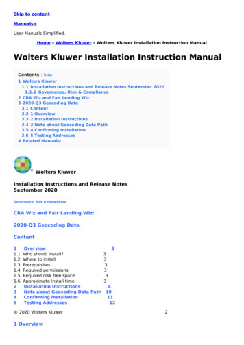
rl-hydraulics.com3. Description3.1 Sub-assemblies and options3.2 NameplateThe main sub-assemblies of the ACN oil-air cooler are the radiator,the housing with mounting points and the fan sub-assembly, consisting of fan, protective grid and motor (æ see Appendix Fig. 1 and2). The fan sub-assembly for sizes ACN 70 to ACN 100 also containsthe motor console used for attaching the motor to the housing(æ see Appendix Fig. 3)Every ACN oil-air cooler is fitted with a nameplate containing thefollowing data (æ see Appendix Fig. 4) and located on the top ofthe housing:ACN oil-air coolers are available with one- or three-phase electricmotors; detailed motor data can be found on the motor nameplate.Optional thermostat switches are available; these can be screwedinto the radiator and activate the fan automatically when the system temperature reaches a certain level. The necessary motor controls must be installed beforehand. Article name Article number Serial number Delivery date Max. operating pressure, static Max. operating pressure, dynamic Max. operating temperatureUnder normal operating conditions, the noise emission level ofoil-air coolers of sizes ACN 5 to ACN 100 is between 61dB(A) and84dB(A) /- 3dB(A). These values can be exceeded if the device is installed in an unfavourable location or operated under extreme conditions.For general information on dimensions and technical data æ seeAppendix, Section “Technical Data and Dimensions”.5
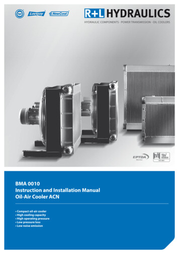
rl-hydraulics.com4. Installation of the oil-air coolerCAUTIONRisk of crushing! To avoid accidents and injuries when lifting, use only the appropriate hoisting equipment and procedures. Ensure that the hoisting machinery and equipment used are in perfect working order and approved forthe weight of the oil/air cooler!4.1 Installation siteWhen selecting the installation site, please ensure that it will haveno adverse effects on the function of the ACN oil-air cooler and thatdraughts or noise will not inconvenience or harm personnel. Airinlets and outlets must not be covered or blocked at any time, sothat cooling air can circulate freely. Recirculation of hot air (exhaust)must be avoided. Please ensure that the distance between the cooler and the nearest wall is equal to or larger than the height of thecooling package. (æ see Appendix Fig. 5)Installation in enclosed spacesWhen the equipment is installed in enclosed spaces, adequate ventilation must be provided so that the warm air produced by the heatexchange process does not increase the temperature in the room.If adequate ventilation cannot be provided, air ducts must be installed between the ACN oil-air cooler and the outside air, allowing air to be sucked directly into the cooler and provide the ventilation required.Outdoor installationThe increased viscosity of oil at low ambient temperatures mustbe taken into consideration when installing the heat exchanger outdoors. This can lead to increased dynamic pressure and system overload when starting from cold, so we recommend the installation of a bypass valve controlled by pressure or temperatureif the cooler is installed outdoors. As an alternative, a thermostatically controlled oil heating system with permanent oil circulationthrough the ACN oil-water cooler can be fitted.Installation in dirty environments (spaces)Installing the heat exchanger in environments with heavily contaminated air results in dirt deposits on the cooling fins. As this reducesthe cooling performance, the equipment must be cleaned regularly when installed in environments strongly contaminated with dustor oil (æ see Appendix Fig. 8. Cleaning).4.3 Electrical connectionsDANGERRisk of electrocution! Electrical equipment must be installedand connected to the mains by a qualified electrician!DANGERRisk of electrocution! Ensure that the device is not connected to the mains electricity supply during installation!CAUTIONCheck mains voltage and frequency! To avoid damage to theACN oil-air cooler or electrical systems, always compare theinformation regarding mains voltage and frequency givenon the motor nameplate before connecting the oil-air cooler to the mains and.WARNINGOverload protection! Electric motors must be properly protected against overload in accordance with the customarytechnical rules and national regulations.4.4 Hydraulic connectionsWARNINGConnection must be free of tension and vibration! To prevent damage to the radiator, all hydraulic connectionsshould be free of tension or vibration. R L HYDRAULICS recommends the use of suitable hydraulic lines or compensators for the connection of the ACN oil-air cooler.The oil-side connection of the ACN oil-air cooler is effected using themarked connection threads or flanges provided on the upper andlower collection tanks of the radiator (æ see Appendix Fig. 11 12).The connection not in use is sealed with a sealing plug before leaving our factory.The connecting pipes G 3/8” and M22 x 1.5 (ACN 5 – ACN 60) or G 1”(ACN 70 – ACN 100) are intended for the installation of measuringsensors or switches (æ see Appendix Fig. 13).4.2 Installation position and orientationThe installation position does not affect the function of the ACN oilair cooler. However, only the mounting points provided should beused (æ see Appendix Figs. 6 – 8).ACN 5:front mounting flangeACN 10 – 60: Foot brackets orfront mounting flangeACN 70 – 100:Foot brackets orfront mounting flange6
rl-hydraulics.com5. Commissioning and start-upCAUTIONRisk of injury! Before operating for the first time, check thatthe ACN oil-air cooler has been installed and connected correctly.Commissioning and start-up procedure: Please ensure that: the ACN oil-air cooler is complete and none of the components show signs of damage. the ACN oil-air cooler has been connected correctly. the fan can rotate freely and without obstruction - a simpletest is to turn the fan by hand. To prevent obstruction or damage to the fan blades, ensure that there is nothing protrudingthrough the fan guard. all screw-in oil connections have been sufficiently tightened. the housing of the ACN oil-air cooler is free of foreign objects. Turned on the oil supply and check the hydraulic connections forpossible leaks. In the event of a leak, retighten the screw connections; if necessary, replace the connections. Start the electric motor. Check that the fan is rotating in the direction of the arrow on the housing. If a three-phase motor is fitted and the fan is rotating in thewrong direction, reverse the terminal connections. Listen carefully for any unusual noises or vibration. Unusual noises or vibration indicate that the fan or drive motormay be damaged. Damaged components must be replaced immediately (æ see Appendix Section 9.2 Dismantling the electricmotor and fan).6. Operating the unitCAUTIONRisk of burns or scalding! The ACN oil-air cooler can becomevery hot when in operation, so always allow ample time forthe radiator to cool down before touching it. We recommend the installation of a guard to prevent accidental contact.Please ensure that the following maximum permissible values/limits are not exceeded during operation.Max. oil temperature:120 CMax. ambient temperature:40 CMax. operating pressure:26 bar static / 20 bar dynamicMax. power consumption: see motor nameplate7. Maintenance7.1 Regular maintenance workThe user/operator should check the following items at regular intervals to ensure that the ACN oil-air cooler continues to functionproperly and safely: Noise and vibration: Unusual noises or vibration indicate that the fan or drive motormay be damaged. Damaged components must be replaced immediately. (æ see Appendix Section 9.2 Dismantling the electricmotor and fan)Correct mounting:Loose or missing mountings must be tightened or replaced.Soiling of the radiator: Dirt on the radiator will reduce cooling performance and may bean indication of leaks, so the radiator must be cleaned regularly.(æ see Section 8.1 Cleaning the radiator)Oil-tightness of the radiator: Oil leaks can endanger the environment and constitute a risk tohuman health, so any leaky screw connections must be tightened or replaced. If oil is leaking from the radiator itself, the radiator must be replaced. (æ see Section 9.1 Dismantling the radiator)Warning labels: Warning labels must not be damaged or removed. Any defacedor missing labels must be replaced immediately.7.2 Yearly inspections:The electrical installations must be checked by a suitably qualifiedelectrician once a year.7
rl-hydraulics.com8. CleaningDANGERRisk of electrocution! Always disconnect the ACN oil-aircooler from the mains electricity supply during cleaning, especially when water or other liquids are used.CAUTIONRisk of injury! Always switch off drive motor before cleaning and ensure that it cannot be switched on again inadvertently.8.2 Cleaning the inside of the cooler housingThe radiator must be removed in order to clean the inside of thecooler housing (æ see Section 9.1 Dismantling the radiator). As arule, cleaning the cooler housing with compressed air at is sufficient. To prevent dust and dirt from entering the motor, we recommend directing compressed air through the protective grid fromthe motor side. Particularly stubborn dirt can be removed using adegreaser.CAUTIONRisk of burns or scalding! The ACN oil-air cooler can becomevery hot when in operation, so always allow ample time forthe radiator to cool down before touching it. We recommend the installation of a guard to prevent accidental contact.8.1 Cleaning the radiatorThe radiator may be cleaned with compressed air or water. If the radiator is extremely dirty, it can also be cleaned with water using ahigh-pressure cleaner. The water jet must be directed lengthwisealong the fins to avoid damaging them. Add a cleaning agent tothe water if necessary, but please ensure that the cleaning agentused is compatible with aluminium. Oil and grease deposits can bewashed off with hot water. Always cover the motor during cleaning and ensure that the radiator is cold when cleaning it with water.9. Dismantling and assembling the sub-assemblies9.1 Dismantling the radiatorR L Hydraulics accepts no liability for consequential damagecaused by unauthorised repairs and/or modifications carried out bythe user/operator.CAUTIONRisk of injury! Always switch off drive motor before dismantling the radiator and ensure that it cannot be switched onagain inadvertently.CAUTIONRisk of burns or scalding! The ACN oil-air cooler can becomevery hot when in operation, so always allow ample time forthe radiator to cool down before dismantling.CAUTIONRisk of crushing! To avoid injuries caused by the radiator falling, always secure it before loosening the fixing screw.Procedure for dismantling the radiator (æ see Appendix Fig. 14): Turn the system off. Switch off fan motor and ensure that it cannot be restarted inadvertently. Make sure that the system is not under pressure. Shut off oil supply to the cooler. Remove cooler inlet and outlet pipes. Empty radiator completely. Remove the screws fixing the radiator to the housing. Remove the radiator.Procedure for assembling the radiator: Refit radiator Attach the radiator to the housing with the screws provided.Secure screws with Loctite blue or similar liquid thread locker. Attach cooler inlet and outlet pipes to the radiator. Connect motor to the electricity supply.8
rl-hydraulics.com9. Dismantling and assembling the sub-assemblies9.2 D ismantling the electric motor and fanDANGERRisk of electrocution! Ensure that the unit has been disconnected from the mains electricity supply and the electricalwiring is current-free before dismantling des electric motor!CAUTIONRisk of burns or scalding! The ACN oil-air cooler can becomevery hot when in operation, so always allow ample time forthe radiator to cool down before dismantling the electricmotor.ACN 5Procedure for dismantling the electric motor (æ see AppendixFig. 15): Turn off the unit and ensure that it is completely disconnectedfrom the mains electricity supply. Disconnect wiring to and from the motor. Remove screws fastening the protective grid to the frame.Procedure for installing the electric motor: Fasten protective grid to housing with screws and washers.Secure screws with Loctite blue or similar liquid thread locker. Connect motor to the mains electricity supply. For subsequent procedures, see Section 5. “Commissioning andstart-up”.ACN 10 – ACN 60Procedure for dismantling the electric motor (æ see AppendixFig. 16): Turn off the unit and ensure that it is completely disconnectedfrom the mains electricity supply.Disconnect wiring to and from the motor.Secure the motor.Remove screws fastening the protective grid to the frame. Remove fan unit - consisting of protective grid, fan and motor –from the cooler housing. Remove locking screw at the front end of the motor shaft. Remove fan from motor shaft, using a puller if necessary. Release locking screws between protective grid and motor. Remove protective grid.Procedure for installing the electric motor: Attach protective grid to the motor. Fasten protective grid to the motor with screws provided. Securescrews with Loctite blue or similar liquid thread locker. After lightly greasing the motor shaft, fit the fan on the shaft, using a spacer ring if necessary. Securely fasten fan to front end of motor shaft using screw andsuitable washer(s). Attach fan unit – consisting of protective grid, fan and motor - tocooler housing. Fasten protective grid to housing with screws and washers. Secure screws against loosening with Loctite blue or similar liquidthread locker. Check that the fan is centred in its housing and able to rotatefreely. If necessary, slightly loosen screws between protectivegrid and housing, then realign protective grid. Connect motor to the mains electricity supply. For subsequent procedures, see Section 5. “Commissioning andstart-up”.ACN 70 – ACN 100Procedure for dismantling the electric motor (æ see AppendixFig. 17): Turn off the unit and ensure that it is completely disconnectedfrom the mains electricity supply. Disconnect wiring to and from the motor. Secure the motor. Release the screws fastening the protective grid to the housing. Release the screws fastening the motor console to the housing. Remove fan unit – consisting of protective grid, fan, motor console and motor – from the cooler housing. Remove locking screw at the front end of the motor shaft. Remove fan from motor shaft, using a puller if necessary. Remove protective grid. Remove screws fastening the motor console to the motor. Remove motor console.Procedure for installing the electric motor: Attach motor console to motor. Fasten motor console to motor with screws provided. Securescrews with Loctite blue or similar liquid thread locker. Lay protective grid on motor console. After lightly greasing the motor shaft, fit the fan on the shaft. Securely fasten fan to front end of motor shaft using screw andsuitable washer(s). Secure screw against loosening with Loctiteblue or similar liquid thread locker. Attach fan unit – consisting of protective grid, fan, motor consoleand motor – to the housing. Securely fasten motor console to housing with screws and washers. Secure screws against loosening with Loctite blue or similarliquid thread locker. Securely fasten protective grid to housing with screws and washers. Secure screws against loosening with Loctite blue or similarliquid thread locker. Check that the fan is centred in its housing and able to rotatefreely. If necessary, slightly loosen screws between motor console and housing and realign motor console. Connect motor to the mains electricity supply. For subsequent procedures, see Section 5. “Commissioning andstart-up”.9
rl-hydraulics.com10. Important information for Ex-zones10.1 Instruction manual supplement “Ex”If the oil-air filter ACN is operated in or in connection with an explosive atmosphere, the following supplementary instructions inthe “Instruction Manual Ex” must be followed in ad-dition to the instructions in the specification “ACN and DCN oil-air filter” and “BMA0010 Operating Manual and Fitting Instructions / oil-air filter ACN”.10.2 Intended useThe oil-air filter is a component under the terms of RL 94/9/EC andmay only be operated in or in connection with an explosive atmosphere if the conditions below are met.10.2.1 Explosive atmosphereAmbient pressure pU 0.8 to 1.1 barOperation is forbidden in an explosive atmosphere resulting fromexplosive dust or unstable substances as defined in RL 67/548/EEC.10.2.2 Instructions for useThe oil-air filter was designed to be free of ignition sources in accordance with DIN EN 14986. The oil-air filter is available in versionssuitable for the following categories:For use in Zone 1 or Zone 2:CE II 2 G IIB TXFor use in Zone 22:CE II 3 D TX.The minimum ignition energy of combustible dusts is:MZE 10 mJPermissible ambient temperature is:-20 C TU 40 CMaximum surface temperature is dependent on the oil involved.Maximum surface tempera-ture is identical with maximum oil temperature.The ignition temperature of the oil to be cooled must be at least50 C higher than the maximum permissible surface temperature.The presence of dust in the cooling air can cause inadmissible electrostatic charging of the powder coating of the cooler and housing,so the oil-air filter may only be used in a dust-free environment inZone 1 or Zone 2.Rubbing with a dry cloth can cause inadmissible electrostatic charging of the powder coating of the cooler and housing, so only dampcloths may be used for cleaning purposes.The operating company is responsible for ensuring that all requirements for operation as in-tended are met.10.3 Industrial safety instructionsIf the oil-air filter is used as a component of a device or subassembly under the terms of RL 94/9/EC, the manufacturer of the device or sub-assembly is responsible for ensuringand confirming the conformity of the device or sub-assembly with the relevant directive.If the oil-air filter is used as part of an installation, the company operating the installation is obliged to ensure that therequirements of RL 1999/92/EC and any additional nationalrequirements are met.The operating company is obliged to check whether, on thebasis of the instructions for use, the oil-air filter is suitable foroperation in the explosive atmosphere that is actually present.There are no effective ignition sources during trouble-freeoperation of the oil-air filter. The operating company isobliged to perform the checks, maintenance and repairs setout in the instruction manual in order to ensure trouble-freeoperation.The operating company must deactivate any oil-air filterthat is not in full working order. The oil-air filter must not beoperated again before completion of the necessary repairs.10.4 Installation and assemblyInstallation and assembly must be performed in accordancewith the Instruction Manual BMA 0010 and the instructionsprovided in this supplement.Only the self-locking screws supplied with the device maybe used.Any additional components used e.g. temperature or pressure sensors must belong to the Category assigned to therespective installation zone as defined in RL 1999/92/EC. Usecomponents from Category II 2 G for Zone 1, Category II 3 Gfor Zone 2 and Category II 3 D for Zone 22. The manufacturer’s instructions must be followed.Always select a motor in Category II 2 G or II 2 D.The oil-air filter must have a potential-free connection toadjacent components. The required earth resistance is 106ohm.10
rl-hydraulics.com10. Important information for Ex-zones10.5 Checks, maintenance and repairsIn addition to the maintenance instructions contained in theinstruction manual BMA 0010, the following directions mustbe observed in order to prevent and identify faults.Any faults must be rectified immediately in accordance withthe maintenance and repair instructions.The fan must be able to move freely at all times in order toprevent overheating, which can result in surface temperatures reaching inadmissible levels. To this end, clearancesbetween the fan and the housing and radiator grille must bechecked regularly. If the clearances fall below the minimumvalues specified in “TD Annex 7.7, clearance dimensions”, theoil-air filter must be deactivated. It must not be operatedagain until the necessary repairs have been carried out.The oil-air filter must not be used as a step, storage shelf orsupport, as this could lead to an inadmissible reduction ofthe above-mentioned minimum clearances required.As any accumulation of dust on the fan can cause an imbalance that may result in damage to the motor bearings, thefan must be cleaned regularly.10.6 TestingUnder the terms of RL 1999/92/EC, the oil-air filter must betested before first operation to ensure that it is assembledcorrectly and in perfect working order. The tests set out BMA0010 and the additional tests specified below must be carried out and the results documented by qualified personnelor an employee of R L HYDRAULICS GmbH, Werdohl.The clearances between the fan and the housing and the fanand the radiator grille must be checked before first operation and at regular intervals thereafter, see Section 6.The potential-free connection with adjacent componentsand the earth resistance must be checked before first operation and at regular intervals thereafter, see Section 5.Under the terms of RL 1999/92/EC, the oil-air filter must betested at the latest every 3 years to ensure that it is in perfect working order. The tests must be carried out and theresults documented by qualified personnel or an employeeof R L HYDRAULICS GmbH, Werdohl. Testing shall be in accordance with the provisions of BMA 0010 with the additionof the tests specified above.Do not carry out checks, servicing or maintenance work onthe oil-air filter if an explosive atmosphere is present.Suitable safety measures in accordance with DIN EN 1127-1,Annex A must be implemented when work is carried out inan explosive atmosphere. Smoking, fire and naked flamesare prohibited.Only tools defined in DIN EN 1127-1, Annex A as suitable forsuch operating conditions may be used.In order to maintain the explosion protection strategy, onlyreplacement parts specified and approved by the manufacturer may be used in the event of repairs.11
rl-hydraulics.comAPPE N D IXIllustrations & diagramsFig. 1:Sub-assemblies ACN-5132Fig. 2:Sub-assemblies ACN-10 – ACN-601. Radiator2. Housing3. Fan otective gridMotorFoot brackets1.2.3.4.5.6.RadiatorHousingFanProtective gridMotorMotor consoleFig. 3:Sub-assembliesACN-70 – ACN-10012346512
rl-hydraulics.comIllustrationsFig. 4:NameplateFig. 5:Required clearancesFig. 6:Sub-assembliesACN-70 – ACN-100Fig. 7:Mounting pointsACN-10 – ACN-6013
rl-hydraulics.comIllustrationsFig. 8:Mounting points ACN-70 – ACN-100Fig. 9a:Electrical connections ACN-5(230V 50Hz, one phase)LNU2U1ZColour coding:PEU1:Z:U2:PE:Fig. 9b:Electrical connections ACN-5(230/400V 50Hz, three phases)L1L2L3U1V1W1U2V2W2L1U1U2Delta connectionL2V1L3W1V2Star connectionW2BlueBrownBlackGreen/yellowColour coding:L1: BlackL2: BlueL3: BrownU1: BlackV1: BlueW1: BrownU2: GreenV2: WhiteW2: YellowFig. 10a:Electrical connectionsACN-10 – ACN-60 (230 V 50 Hz, one phase)ThermostatswitchU1 ZMU2For terminal assignment,please refer to label in motorterminal box14
rl-hydraulics.comIllustrationsFig. 10b:Electrical connections ACN-10 – ACN-100(230/400V 50Hz, three phases)W2U2V2W2U1L1V1L2Delta connectionW1L3U2U1L1V2V1L2W1L3Star connectionFig. 11:Hydraulic connectionOne-way radiator(ACN-5-1 bis ACN-100-1)Variant a (Standard)Variant b (reduced cooling performance)Fig. 12:Hydraulic connectionTwo-way radiator(ACN-5-2 bis ACN-60-2)Fig. 13:Measurement ports15
rl-hydraulics.comIllustrationsFig. 14:Dismantling the radiatorACN-5 – ACN-60ACN-70 – ACN-100Fig. 15:Dismantling the electric motor ACN-5Fig. 16:Dismantling theelectric motorACN-10 – ACN-60a. Dismantling fan sub-assemblyb. Dismantling fan and protective grida. Dismantling fan sub-assemblyb. Dismantling fan and protective gridFig. 17:Dismantling electric motorACN-70 – ACN-10016
rl-hydraulics.comTechnical data and dimensionsACN-5 – ACN-60 DimensionsIJ G3/8"AHK (3x)GM22 x 1,5Ø12 x 20DEFBFrame -507126704702131305547261063183G1 1/2"ACN-607126705002441305547261094183G1 1/2"* ACN-5 without mounting bracketsTechnical dataSeriesMotorPower consumptionAirflowNoise levelNoise levelWeightOrder code[kW/UPM][A][m3/sec.]1 m [dB(A)]7 m 0.1-SACN-50.10/25
The ACN oil-air cooler is 'partly completed machinery' under the terms of the EU Directive 2006/42/EC. By applying standard DIN EN ISO 12100:2011-03 during design and construction of the ACN oil-air cooler, the manufacturer has taken into account the general requirements regarding safety and ergo-nomics. WARNING