Transcription
Installation instructionsfor Egger LaminateFlooring with CLIC it!installation system
Required Inspection Prior to Installation / subfloor / room climate1. Required Inspection Prior to InstallationEGGER Laminate Flooring is made following very precise operation steps in state-of-the-art production plants. Stringent qualityinspections are carried out regularly both during and at the end of the manufacturing process. There may be occasions however,when damage to individual boards occurs, for example during transport, despite the quality checks.Accordingly, the flooring boards must be inspected for possible defects prior to and during installation. Damaged flooring boards orthose that differ from the norm should not be installed but returned to the supplier to be replaced.2. Subfloor2.1As a general rule: The subfloor prepared for installation must be dry, clean, free of separating agents, crack-free, level, as well as display tensileand compression strength in accordance with DIN 18365 and DIN 18202. With regard to evenness, the raised requirement of 2 mm/m must be observed. The flooring contractor must, within the scope of the inspection and due diligence requirement, make sure prior to installingthe flooring that the subfloor has the required installation suitability and must report “concerns” in writing if the subfloor is notsuitable for installation, i.e. if there are defects and / or there is a risk of damage to the top floor due to its construction.When assessing installation suitability for EGGER’s Laminate Flooring, attention should be paid, in particular, to the points below.In the case of failure to comply, all guarantee and warranty claims will become void.Inspections of the moisture level of the subfloorThe inspections of the subfloor moisture must be carried out to determine whether the subfloor is sufficiently dry.Installation suitability is determined by measuring the water content in CM %. When carrying out inspections with the CM device(CM method), the following limit values must not be exceeded:Cement screedCalcium sulphate screedwithout floor heating 2.0 CM % 0.5 CM %with floor heating (heated screed) 1.8 CM % 0.3 CM %These values apply to screeds without additives. With the use of additives and in case of fast-drying screed, the measurements andlimits specified by the respective manufacturer shall apply.In some countries / regions, installation suitability is determined by measuring the corresponding relative humidity, as describedbelow. KRL measurement:BS 5325:NT Built 439:ASTM F2170:Limit value 75% rH for unheated screed 65% and rH for heated screedLimit value 75% rH (surface measurement, United Kingdom)Limit value 85% rH (Scandinavia)Limit value 80% rH (SITU sample, North America)2
Required Inspection Prior to Installation / subfloor / room climateInspections of the evenness of the subfloorThe inspections of the evenness are based on common standards and are conducted by placing a yardstick / straight-edge on thehigh points of the surface and determining the gauge at the deepest location in relation to the bearing surfaces (measuring pointintervals). A vertical deviation of max. 2 mm is allowed at 100 cm measuring point intervals. Larger deviations should be levelled bysuitable measures (e.g. with self-levelling compounds).Inspections of the strength / load-bearing capacity of the subfloorThe subfloor must be a sealed, self-supporting layer.Inspections of the cleanliness of the subfloorThe subfloor must be kept clean and be in a vacuum-cleaned condition – at all times.Inspections of the atmospheric conditionsThe following conditions should be met prior to, during and after installation: an air temperature of at least 18 C a floor surface temperature of at least 15 C a relative air humidity of between 40 % and 70 %.2.2Suitable subfloorsAll subfloors are considered suitable for the floating installation of EGGER Laminate Flooring if they are suitable for installation inaccordance with the above-mentioned requirements. In particular, these include: all types of screed including hot water-heated screed OSB and chipboard structures fibreboards existing floor coverings such as PVC, linoleum, natural stone slabs and ceramic tiles.Screeds with hot water floor heating (heated screeds)When preparing a heated flooring structure, all those involved (builder, architect, specialist heating planner, heating engineer,installer, floor covering manufacturer) must work together in a coordinated manner. All surface-heated flooring requires appropriateplanning and coordination of the heating system and screed in order to ensure maximum long-term performance without causingany damage. Alongside the usual inspections on the installation subfloor, the underfloor heating / cooling function must beinspected (functional heating / cooling). This evidence of the screed construction being properly heated up and cooled down mustbe provided each season and be documented by means of a heating and cooling protocol.When heating the load and heat distribution layer, a distinction is made between functional heating and floor curing heating. Functional heating is the proof of the heating installer that a proper structure has been built and is used to review thefunctionality of heated flooring structures. Floor curing heating is the expelling of the residual moisture in the screed until installation suitability is reached.3
Subfloors / underlay materialsAttention! Functional heating does not guarantee that the screed has reached the residual moisture required for installation suitability.Accordingly, floor curing heating is necessary as a rule. EGGER Laminate Flooring is generally installed “floating”. When installing floating on heated screed, attention should be paidto the heat conductivity values of the laminate flooring and the insulating underlay. The total of the heat conductivity values forall components must be 0.15 m²K/W. When using insulating underlays that are not from the EGGER range of accessories, anyguarantee is rejected with regards to compliance with the effective maximum permitted heat conductivity of the overall structurefor a floating installation on heated screeds. The surface temperature of the heated flooring structure must not exceed 28 C and heating up too quickly must be avoided. Installation on surface heating systems with night storage function is not permitted.Subfloors with a limited degree of suitabilityElectric surface / foil heating systems and elastic old floor coverings (PVC, cushion vinyl and linoleum) are considered to besubfloors with a limited degree of suitability.EGGER Laminate Flooring may only be laid on electric surface / foil heating systems that: are equipped with temperature sensors and controllers have been designed relatively recently (from 2005) and have technical approval from the heating manufacturer for LaminateFlooring laid over the entire area without interruption – partial installation (e.g. only in walking area of the bed room) is not permitted toavoid thermal gradient inside the floor covering on the one hand and, on the other, to ensure even heat distribution. are not night storage heaters.The installation of EGGER Laminate Flooring on existing floor coverings made of PVC, cushion vinyl and linoleum is only permitted ifthese are fully and firmly bonded, if there are no detachments and / or cracks and if no surface heating is present.Unsuitable subfloorsEGGER Laminate Flooring may never be installed on textile floor coverings. Textile floor coverings and carpets are unsuitable assubfloors for reasons of strength and hygiene and must be removed. In the case of failure to comply, all guarantee and warrantyclaims will become void.Mineral subfloorsFor floating installation of Laminate Flooring on mineral subfloors (screeds, heated screeds, tiles, etc.), a moisture protection filmwith SD value 75 m must always be installed as a vapour barrier over the entire surface and in a trough shape. When professionallyinstalled, the moisture protection film must overlap by 5 - 20 cm in the joining areas depending on the design. In order to improvethe impact noise insulation, a system-specific insulation underlay to be placed on top is recommended. When using EGGER SilenzioDuo, EGGER Silenzio Easy SD or a comparable 2-in-1 insulation underlay with integrated moisture protection, no separate moistureprotection film is required.Floor structure:1. Mineral subfloor2. Underlay materials (moisture protection film (vapour barrier) and impact noise insulation underlay)Option A: EGGER Silenzio Duo or Silenzio Easy SDOption B: EGGER Aqua Aluflex and EGGER Silenzio Easy or EGGER Aqua Aluflex and EGGER Silenzio Cork3. EGGER Laminate flooring4
Subfloors / underlay materials / wet and damp areas, locations and / or conditionsAttention!For EGGER Laminate Flooring with Silenzio underlay laminated on the back, no further impact noise insulation underlay may beinstalled.Subfloors made of wood (OSB, chipboard and fibreboard, real wood floor boards)Any loose floor boards or other types of boards should be properly screwed down. The Laminate Flooring boards are to be installedat right angles to the longitudinal direction of the wooden floor boards.To improve the impact noise insulation, a system-specific insulation underlay should be installed under Laminate Flooring. EGGERLaminate Flooring with Silenzio underlay mat laminated on the back are laid directly on top of the wood-based flooring boards orwooden floor boards.Floor structure:1. Wood-based subfloor2. Impact noise insulation underlay, such as EGGER Silenzio Easy or EGGER Silenzio Cork3. EGGER Laminate flooringUnderlay materials On mineral subfloors, a moisture protection film, SD value 75 m, must be installed over the whole area in a trough shape. Anexception is the use of EGGER Silenzio Duo, EGGER Silenzio Easy SD or a comparable 2-in-1 insulation underlay with integratedmoisture protection. In this case, a separate moisture protection film is not necessary. Do not place moisture protection film on wooden subfloors. A system-specific EGGER Silenzio underlay mat must be used under EGGER Laminate Flooring. Alternative underlay mats areavailable at www.egger.com. The exception to this is when using EGGER Laminate Flooring with a Silenzio underlay mat laminated to the back. No otherimpact noise insulation underlay must be used in this case.Wet / damp areas, locations and / or conditionsEGGER Laminate Flooring is not suitable for installation in wet and damp areas, locations and / or conditions, such as bathrooms,shower rooms, saunas or outdoors. In the case of failure to comply, all guarantee and warranty claims will become void.The Aqua Laminate Flooring collections are the only exception. EGGER Aqua Laminate Flooring can also be installed in bathroomswith normal household use without a floor drain with bath tub or shower tray, where the floor surface is only temporarily and brieflyexposed to splashing water. These include private bathrooms, but also hotel bathrooms that are only used in the morning andevening, or kitchens, corridors, entrance areas and apartments in nursing homes.5
Prior to installation3. Prior to installationConditioning the boardsPrior to installation, the packages of Laminate Flooring must be stored in the room where they will be installed or in a room with thesame climate conditions. Acclimatisation takes place in the following conditions: packaged for a period of at least 48 hours laid flat with a minimum of 50 cm distance from all walls the room temperature is at least 18 C the surface temperature of the floor is at least 15 C at a relative atmospheric humidity of between 40 % and 70 %.Tools & protective equipment electric jigsaw, circular or chop saw, laminate cutter and cutter knife if necessary, drill and metal saw for fixing / cutting floor profiles and skirting boards to size folding rule, angle and carpenter pencil tapping block, hammer and possibly a crowbar spacerWear suitable protective equipment such as safety goggles, dust mask and gloves.Direction of installationLaminate Flooring looks best when the floor boards are installed parallel to the incidence of light. However, there are bindingrequirements for the direction of installation only for subfloors made of wooden floor boards or strip parquet / wooden floorsarranged in English bond. In these cases, the flooring must be installed at right angles to the longitudinal direction of the floorboards / strip parquet.Built-in kitchens / built-in cabinetsDo not install Laminate Flooring under kitchen units or fixed and / or heavy built-in cupboards (the flooring is / will then be fixedon one side). It is recommended to install Laminate Flooring only up to behind the skirting panel, so that the flooring can be easilyremoved at any time.6
Prior to installationIf this is not possible, the following alternatives are available:A) Decoupling:1. Install the Laminate Flooring over the entire surface and assemble the kitchen unit / built-in cupboard.2. Decouple the Laminate Flooring surface by sawing between the furniture feet and the skirting panel.3. Cover by floor profile or leave open (no visible area).B) Bolt circle drill:1. Install the Laminate Flooring over the entire surface.2. Determine the position of the furniture feet, mark them on the laminate flooring and saw them out using a bolt circle drill(Ø furniture foot 16 mm).3. Assemble the kitchen unit / built-in cupboard.Planning the first and last rowPrior to installation, the room must be measured to determine whether the width of the first row should be reduced. This is alwaysnecessary if the last row would mathematically be narrower than 5 cm and / or to give the first and last row the same width.Wall distance and expansion gapsEGGER Laminate Flooring – like all wood-based floors – are subject to a certain motion behaviour due to changing room climateconditions. Due to this material-specific motion behaviour, edge / wall joints must be installed for all fixed structures such as walls,door frames, pipe penetrations, pillars and stairs. In addition, motion joints must always be installed in the following surface areasand surface sizes: door thresholds passageways angled areas for room lengths and / or widths of more than 10 m.Sufficiently dimensioned wall distance and expansion gaps, with a width of at least 8 - 10 mm, do not impede the motion of theinstalled floor surface.The guiding formula is as follows: 1.5 mm expansion gap (circumferential) per metre of floor surface (for example: 10 m room length 15 mm wall distance to both walls).The wall distance and expansion gaps are covered by skirting board and / or floor profiles.Note: With most types of profile, it is necessary to fit the base (sub-profile) to take the cover profile prior to installing LaminateFlooring.7
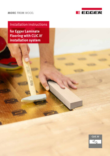
Installation4. Installation4.1. Basic information The installation must be carried out in daylight. Review the flooring boards for possible faults prior to and during installation. Flooring boards with visible damage or defectsmust not be installed. EGGER Laminate Flooring is installed “floating”, i.e. without fixing (no bonding / screwing etc.) the flooring boards to the subfloor.With floating installation, the individual floor boards are installed using the CLIC it! locking system to connect and place theindividual boards. Note: The only exception are the Aqua Laminate Flooring collections. These floors can also be bonded over the entire surface(for details see section “Aqua Laminate Flooring”). Make sure that you understand the difference between the groove and tongue on the board. Start installing in a left-hand corner of the room with both tongue sides of the first panel facing the wall and both grooved sidesfacing the installer. The short ends (header joints) must be staggered at least 20 cm or 50 cm for the “Long” format. In case of products supplied with factory-produced bevel and / or with special design (e.g. tiles decor), ensure the short end(header joint) is even according to the bevel and / or pattern configuration. Remaining pieces can be used as the start or end board of each row if they are at least 20 cm long ( 50 cm for the “Long” format),and thus the minimum offset of the short ends (header joints) from row to row is maintained. In order to prepare the last row of boards for installation, take the board and place it exactly on top of the row before last. Bymeans of a residual board (board width), it is possible to transfer the wall structures to the board within a pre-chosen distance. When cutting to size by using a circular, plunge or cross-cut saw, place the floor boards with the decor side facing upwards. Whencutting to size by using jigsaw, move it over the back of the board.8
Installation4.2. Installation methodsThe installation of EGGER Laminate Flooring with CLIC it! installation system can be carried out using 3 different installationmethods: Method A: angled in at the front and long side board by board Method B: angled along the long side and tapped in at the short end (header joint) board by board Method C: installation in rows by angling the front and long sideswww.egger.com/qr-installation-clicit4.2.1. Installation method A Place the first board in the left-hand corner of the room so that both tongue sides face the wall (Fig. C1a). Join the boards of the first row by angling the front tongue of the board to be installed diagonally from above into the front grooveof the already installed board and lay it down with light pressure on the front side (Fig. C1a). The last board in the first row ismarked and cut to the required length and installed as specified above. Make sure that the boards of the first row are aligned with precision on the long side. It is recommended to place a piece ofthe flooring as a stop / spacer between the wall and the first row, respectively in the area of the end joints. After the first 2-3rows have been installed, remove the boards acting as stops, and align the flooring area installed up to this point with the wall,maintaining the distance from the wall and inserting the spacers. (Fig. C1a to C 8a) Angle the first board of the second and each subsequent row diagonally from above with the tongue in the groove of thepreviously installed row and lay it down with light pressure on the long side (Fig. C3a). Install all subsequent boards of a row as follows:1. Angle the front tongue at an angle from above into the front groove of the previously installed board and lay the board (withlight pressure on the front side) as close as possible to the long edge of the installed row (Fig. C4a).2. Slightly lift the board to be laid on the long side (Fig. C5a).3. Now click the tongue on the long side diagonally from above into the groove of the previous row (push in) and lower the board,thus closing the long side joint (Fig. C6a).Note: Please note that when lifting and angling the board on the long side, the adjacent board on the left is automatically liftedas well due to the already locked front end.4. Make sure that all joints are completely closed, i.e. that no joints are visible. If there are isolated, smaller joints, these can beclosed by light, controlled tapping with a tapping block.aaaa1125a6a7a8a121Install all remaining boards as described above, by cutting the length of the first and / or last board of any row to the necessary size.9
Installation4.2.2. Installation method B: The boards in the first two rows can be installed simultaneously, which means constantly alternating them whilst complying withthe minimum offset of the header joints.8 - 10 mmWall8 - 10 mm Board 1 lay out in a left-hand corner of the room so that both tongue sides face the wall. Board 2 angling the long side of this shortened board. For this purpose, place the longitudinal tongue at a slight angle from above into the longitudinal groove of board 1 and lowerboard 2. Board 3 angle in on the long side & tap in on the short side (do not hit!). To begin with, place the longitudinal tongue at a slight angle from above into the longitudinal groove of board 1 (Fig. C2b). In this angled position, push board 3 as close as possible to the front edge of board 2 so that the front tongue of board 3 lieson the groove milling of board 2 (Fig. C3b). Then lock the longitudinal joint by lowering board 3. Briefly make sure that the height of the front tongue is not too highabove the header joint of board 2 (Fig. C3b). If the height is correct, lock the header joint by lightly tapping horizontally with a hammer and tapping block (Fig. C3b).Note: To adjust the height level, it is recommended to place a flooring board on the long side in the area of the front joint. Excessive hammering can lead to damage to the header joint, which may only become apparent later in the course of use. Board 4 opposite longitudinal angling and tapping of the short side as above. Place the longitudinal groove at a slight angle under the longitudinal tongue of board 3 (Fig. C4b). In this angled position, push board 4 as close as possible to the front edge of board 1 so that the front tongue of board 4 lieson the groove milling of board 1 (Fig. C4b). Then lock the longitudinal joint by lowering board 4. Briefly make sure here as well that the height of the front tongue is nottoo high above the front joints of board 1 (Fig. C4b). If the height is correct, lock the header joint by lightly tapping horizontally with a hammer and tapping block (Fig. C5b). Board 5 longitudinal angling and tapping on the front end (see board 3) Board 6 longitudinal angling and tapping on the front end (see board 4) Board 7 longitudinal angling and tapping on the front end (see board 3) Board 8 longitudinal angling and tapping on the front end (see board 4) Install all remaining boards of the first two rows as described above, by cutting the length of the first and / or last board of anyrow to the necessary size. Subsequently, position the first two rows while observing the wall distance to the long side wall and place the spacers. Angle the first board of the third and each subsequent row diagonally from above with the tongue in the groove of the previouslyinstalled row and lay it down with light pressure on the long side. Install all subsequent boards of a row as follows: To begin with, insert the longitudinal tongue diagonally from above into the longitudinal groove of the previous row. In this angled position, push the board as close as possible to the front edge of the left board so that the front tongue of theboard to be installed lies on the groove milling of the left board. Then lock the longitudinal joint by lowering the board. Briefly make sure that the height of the front tongue is not too highabove the front joint of the left board. If the height is correct, lock the header joint by lightly tapping horizontally with a hammer and tapping block. Install all remaining boards as described above, by cutting the length of the first and / or last board of any row to thenecessary size.10
Installation*4.2.3. Installation method C Place the first board in the left-hand corner of the room so that both tongue sides face the wall (Fig. C1c). Join the boards of the first row by angling the front tongue of the board to be installed diagonally from above into the front grooveof the already installed board and lay it down with light pressure on the front side (Fig. C1c). The last board in the first row ismarked and cut to the required length and installed as specified above. Make sure that the boards of the first row are aligned with precision on the long side. It is recommended to place a flooring boardas a stop / spacer between the wall and the first row, respectively in the area of the header joints (Fig. C1c to C6c). After the first2-3 rows have been installed, remove the boards acting as stops, and align the flooring area installed up to this point with thewall, maintaining the distance from the long side wall and inserting the spacers. (Fig. C7c & C8c). Install the first board of the second and each subsequent row with the long side tongue over the long side top groove of thepreviously installed row without closing the locking system (Fig. C3c). All subsequent boards of a row are first connected at the front end (Fig. C4c). Angle the front tongue at an angle from above into the front groove of the previously installed board and lay the board (withlight pressure on the front side) as close as possible to the long edge of the installed row, so that the tongue lies on the longside top groove of the previous row. Then, when all boards of a row are connected at the front end, close the long side locking system (Fig. C5c and C6c). Slightly lift the start board on the long side. Now click the long side tongue, in this angled position and with slight pressure, into the groove of the previous row (pushin). Continue this from left to right until the entire row is connected to the previously installed row and lies flat.Note: Pay attention that the panels are not displaced along the short sides. Make sure that all joints are completely closed, i.e. that no joints are visible. If there are isolated, smaller joints, these canbe closed by light, controlled tapping with a tapping block. Install all remaining boards as described above, adjusting the length of the first and / or last board of any row if necessary.11
Installation4.3. Additional installation instructionsCommercial applications of classes 31, 32 and 33Commercial applications can be expected to be exposed to above-average levels of moisture. For this reason, additional sealingwith PVAC glue (D3), is prescribed in these areas (with the exception of Aqua products). Apply the sealing glue to the front andlong side tongue in such a way that it exits upwards along the entire length of the joint when the boards are joined together. Makesure that the boards below the sealing glue are installed without a gap. Excess sealing glue is easy to remove from the surfaceimmediately or after a short drying period.PVAC glue (D3)PVAC glue (D3)Pipes Measure the position of the pipes and mark it on the panel (allow for edge joint).Drill at least 16 mm larger than the diameter of the pipe.Saw the holes at a 45 angle.Fit and glue the sawn piece.12
InstallationDoor frames If there are wooden door frames, it is recommended to shorten these by the installation height (flooring plus underlay materials)in consultation with the customer. Then install the Laminate Flooring underneath the door frame by using the appropriate wall distance. If the installation takes youto such a frame, the respective board can be angled longitudinally and lowered before the frame. Then the board is tapped underthe door frame into the header joint with a hammer and tapping block by laying it flat on the floor and locked. If the door frame cannot be shortened, a standard PE joint filler profile must be inserted into the surrounding expansion gap (inthe area of the door frame) and rubbed / covered with silicone.Flooring profiles and skirting boardsAfter finishing the professional installation of the Laminate Flooring, both the necessary flooring profiles and skirting boards areinstalled. Assembly instructions are included with the accessories.Removal / dismantling of boardsIn order to remove installed boards without destroying them, you first have to unlock the entire row by tilting it and then detach thepanels at the short ends while tilted. Proceed with great care in order to avoid damaging the tongue and groove.abcabab13
Aqua Laminate Flooring5. Aqua Laminate FlooringEGGER Aqua Laminate Flooring* can also: Be installed in bathrooms with normal household use without a floor drain with bath tub or shower tray, wherethe floor surface is only temporarily and briefly exposed to splashing water. These include private bathrooms, but also hotelbathrooms that are only used in the morning and evening, or kitchens, corridors, entrance areas and apartments in nursinghomes. Be installed by means of full-surface bonding.*Applications exclude wet areas, locations and / or conditions (such as for example, saunas, steam baths, shower cabins or cells,community laundry rooms and swimming pool areas), areas with permanent and increased moisture or liquid exposure, bathroomswith floor drain, as well as any outdoor area.5.1. Floating installation in bathroomsAqua Laminate Flooring is suitable for floating installation in bathrooms on all subfloors listed below if they meet therequirements for installation suitability described under section 2.1.: all types of screed including hot water-heated screed ceramic tiles.Furthermore, the subfloor must be properly sealed (see DIN 18534 Waterproofing for indoor applications & water action classes) inorder to permanently prevent moisture damage to the construction.Floor structure for bathroom use:1.subfloor (as previously named)2. construction sealing (composite waterproofing, for indoor applications)3. underlay mats plus sealing off wall connection area Option A: EGGER Silenzio Duo & sealing tape Option B: EGGER Silenzio Easy SD & sealing tape Option C: EGGER Aqua Aluflex & sealing tape & EGGER Silenzio Easy4. EGGER Aqua Laminate Flooringmoisture barrier & sealing tapeAll decors shown and mentioned are reproductions.14
Aqua Laminate FlooringThe floating installation of Aqua Laminate Flooring in bathrooms is carried out using one of the methods described in section 4.2.,whereby the individual floor boards are locked using the CLIC it! connection.Note! It is absolutely necessary to ensure the full-surface installation of the system-specific moisture protection film and to use a tapeto seal off the wall connection areas in a trough shape Only transition, adjustment an
To improve the impact noise insulation, a system-specific insulation underlay should be installed under Laminate Flooring. EGGER Laminate Flooring with Silenzio underlay mat laminated on the back are laid directly on top of the wood-based flooring boards or wooden floor boards. Floor structure: 1. Wood-based subfloor 2.