Transcription
Series 5600PG Preglazable Curtainwall Installation InstructionsSERIES 5600PG PREGLAZABLE CURTAINWALLEFCO (9‐3‐21)Page 1
Series 5600PG Preglazable Curtainwall Installation InstructionsPageSection1. General Notes and Guidelines .3-42. Parts Identification . .5-83. Setting and Anchoring Units . .9-134. Horizontal Stacking of UnitsA. Captured System . .14-17B. SSG System . .18-215. Recommended Perimeter sealing . .22A. Critical Conditions at Captured System .23B. Critical Conditions at SSG System .246. Captured System Pressure Plates .25-277. Captured System Perimeter Pressure Plates .288. Captured System Covers .299. SSG System Perimeter Adapters . .30-3110. SSG System Exterior Weather Seals .3211. Optional Perimeter Sealing .33-34Note:Prior to beginning installation inspect all units to verify that they have been properly assembled per the EFCO 5600PG assembly instructions.Pay special attention to mull plugs and to gaskets at horizontal and vertical stacks.Minimizing CondensationNote: Please reference EFCO’s “Understanding Condensation” brochure which can be obtained through your EFCO representative.Condensation will form on any surface when unfavorable conditions (regarding interior temperature, relative humidity and exteriortemperature) are present. When the formation of excessive condensation is a concern, it is highly recommended that a design professional is utilized to perform an analysis of theshop drawings to recommend the best possible installation methods. Please contact your EFCO representative forinformation on EFCO’s Thermal Analysis Services.Many current installation practices lead to an increase in the possibility of the formation of condensation. Though not all inclusive, the list of examples below illustratesconditions under which condensation is likely to occur:1. Bridging the system thermal break with non-thermally broken metal flashing or lintels that are exposed to the exterior2. System exposure to cold air cavities3. Interior relative humidity levels not maintained at recommended levels, see EFCO’s “Understanding Condensation” brochure4. Inadequate separation between system and surrounding condition at perimeter5. Product combinations during the shop drawing stage that result in bridging thermal breaks of one or all products involvedEFCO (9‐3‐21)Page 2
Series 5600PG Preglazable Curtainwall Installation InstructionsSecƟon 1: General Notes and GuidelinesHANDLING / STORING / PROTECTING ALUMINUMThe following guidelines are recommended to ensure early acceptance of your products and workmanship.A. HANDLE CAREFULLY - Store with adequate separation between components so the material will not rub together. Store the material off theground. Protect materials against weather elements and other construction trades.B. KEEP MATERIAL AWAY FROM WATER, MUD, AND SPRAY - Prevent cement, plaster, and other materials from contacting with and damaging thefinish. Do not allow moisture to be trapped between the finished surface and the wrapping material.C. PROTECT MATERIALS AFTER ERECTION - Wrap or erect screens of plastic sheeting over material. Cement, plaster, terrazzo, and other alkalinematerials are very harmful to the finish and are to be immediately removed with soap and water. Under no circumstances should these materials be allowedto dry or permanent staining may occur.GENERAL GUIDELINESThe following practices are recommended for all installations:A. REVIEW CONTRACT DOCUMENTS – Become thoroughly familiar with the project. Check shop drawings, installation instructions, architectural drawingsand shipping lists. The shop drawings take precedence and include specific details for the project. Shop drawings govern when conflicting information existsin the assembly and installation instructions. Note any field verified notes on the shop drawings prior to installing. EFCO assembly and installation instructionsare general in nature and cover many typical conditions, but cannot cover all applications that could apply to this systemB. INSTALL ALL FRAMING MATERIAL PLUMB, LEVEL, AND TRUE – Proper alignment and relationships to benchmarks and column centerlines, asestablished by the architectural drawings and the general contractor, must be maintained.ERECTION SEQUENCE - The sequence of erection should be coordinated with the project general contractor to prevent delays and minimize therisk of material damage. Note: When preset anchors are required, coordinate and supervise anchor and insert placement with the general contractorincluding insert layout drawings, where required. Manufacturing, assembly, glazing, and shipment of the preglazed units must be carefully coordinated withthe general contractor to ensure a continuous and sustained flow of materials to the appropriate areas of the project to meet the project schedule.D. PERIMETER CONDITIONS - Verify that all job site conditions and accompanying substrates receiving the installation are in accordance with thecontract documents. If deviations occur, notification must be given in writing to the general contractor and differences resolved before proceeding further withthe installation in the area in question.E. ISOLATION OF ALUMINUM - Prevent all aluminum from coming in direct contact with masonry or dissimilar materials by means of an appropriate primer.Typical slab anchors may be set directly onto concrete surfaces in a block-out pocket at the edge of the slab. The block-out pocket is later filled in with groutthereby covering the slab anchor. In such cases, a heavy coat of zinc chromate or bituminous paint must be pre-applied to the slab anchor.F. SHIPMENT VERIFICATION - Verify contents of all material shipments received upon their arrival. Verify quantity and correct finishes. Notify EFCOimmediately of any discrepancies or damage that may have occurred.EFCO (9‐3‐21)Page 3
Series 5600PG Preglazable Curtainwall Installation InstructionsSecƟon 1: General Notes and Guidelines, cont.G. SEALANT - All sealant must meet [ASTM C 920, CLASS 50]. For the purposes of these instructions, sealant is to be defined as the following:SEALANT - A weather resistant, gunnable liquid filler which when cured provides a resilient, flexible ( 50% movement capability min.) air and water sealbetween similar and dissimilar materials.All sealant must be compatible with all surfaces on which adhesion is required, including other sealant surfaces. All frame surfaces should be cleaned withalcohol, dry, dust, and frost free. If a primer is required, it must be applied to clean surfaces. All perimeter substrates shall be clean and properly treated toreceive sealant. All sealants and primers must be applied according to the sealant manufacturers instructions and recommendations.This system is designed and has been tested to utilize silicone sealants at all internal joineries, i.e., joint plugs, gasket intersections, etc.It is the responsibility of the glazing contractor to submit a statement from the sealant manufacturer indicating that glass and glazing materials have beentested for compatibility, adhesion with glazing sealants, and interpreting test results relative to material performance, including recommendations for primersand substrate preparation required to obtain adhesion. The chemical compatibility of all glazing materials and framing sealants with each other and with likematerials used in glass fabrication must be established.Maintain caulk joints as shown in the approved shop drawings. A 1” minimum joint is required at the head and jamb condition to accommodate installation,building movements, and thermal expansion and contraction.EFCO (9‐3‐21)Page 4
Series 5600PG Preglazable Curtainwall Installation InstructionsSection 2: Parts Identification - Profiles and Accessories.Note: Parts not to scaleNote: Parts not to scaleEFCO (9‐3‐21)Page 5
Series 5600PG Preglazable Curtainwall Installation InstructionsSection 2: Parts Identification - Profiles and Accessories, cont.Note: Parts not to scaleEFCO (9‐3‐21)Page 6
Series 5600PG Preglazable Curtainwall Installation InstructionsSection 2: Parts Identification - Small Parts.Small Parts in Install Instructions:Note: Parts not to scaleEFCO (9‐3‐21)Page 7
Series 5600PG Preglazable Curtainwall Installation InstructionsSection 2: Parts Identification - Small Parts, cont.Generic Small Parts Reference Sheet:Note: Parts not to scaleEFCO (9‐3‐21)Page 8
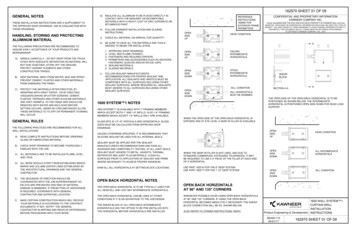
Series 5600PG Preglazable Curtainwall Installation InstructionsSection 3: Setting and Anchoring UnitsSetting First Unit at SillFigure 1Tape to temporarilyhold anchor in placeNote: Typically “F” anchors will be used in all locations, howeversometimes due to structural requirements a “T” anchor will be required (see shop drawings/contract documents for anchor type, sizeand hole location).1. Insert “F” or “T” anchors into both jambs of the unit and temporarily tape in place (Figure 1).2. At the condition jamb, the leg of the “F” anchor must be placedunder the unit.*Captured mullion shown;anchoring of SSG mullions is similar.3. Drill clearance holes in the sill horizontal, at the jamb condition, toaccess the “F” anchor for anchorage to the substrate (Figure 2).Note: Clearance holes will also be required at the head horizontal ofthe top most unit at the jamb condition.Anchorage holes percontract documentsNote: These clearance holes are also required on the head and sillmember at both sides of split mulls, if “T” anchors are used.Note: In some cases it may be possible to place the sill “F” and “T”anchors on the substrate prior to installing the bottom units.Clearance holesFigure 2EFCO (9‐3‐21)Page 9
Series 5600PG Preglazable Curtainwall Installation InstructionsSection 3: Setting and Anchoring Units, cont.Figure 4Anchorage thoughclearance holes4. Set the first unit in place shimming between the vertical mullionsand “F” or “T” anchors ensuring that the unit is set in a level position. Remember to place a separator between the “F” and “T”anchors and the substrate, to separate dissimilar materials.5. Once the unit is in the proper position, plumb, and level, fastenthe “F” or “T” anchors to the substrate per the contract documents(Figures 3 & 4).6. After the unit is properly anchored, install the cover onto the sillhorizontal. (Figure 5).Note: The process of anchoring the head at the top most unit is similar. For proper system movement, exclude shims between mullionand “F” and “T” anchors at head.Place shims at anchorunderneath mullNote: Anchoring of captured mulls and SSG mulls is similar.Figure 3Figure 5Anchors per contractdocumentsPlace shims at anchorunderneath mullEFCO (9‐3‐21)Install cover after the unithas been properly anchoredPage 10
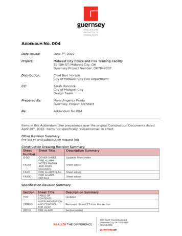
Series 5600PG Preglazable Curtainwall Installation InstructionsSection 3: Setting and Anchoring Units, cont.Figure 6.1Dead load and wind load anchor installation1. Attach dead load/wind load anchors to the substrate per contract documents.2. Leave the anchors to the substrate loose so that they can slide apart via theslots, and slide them as far open as possible to allow clearance for the unitscoming in. (Slot Detail: Figure 7, next page)3. Set first unit in place. Once the unit is properly positioned, plumb, and levelslide the anchor into position leaving 1/4” between it and the mullion. Do notshim between the anchor and the mullion, leave room for movement. Tightenthe anchor to the substrate (Figure 6.1).4. Match drill through the mullion and start the bolts through the mullion.5. Ensure that the other mid-span anchor is slid as far away as possible. Installthe next unit. Once the unit is properly positioned, plumb, and level slide theanchor into position, leaving 1/4” between it and the mullion. Do not shim between the mid-span anchor and the mullion; leave room for movement. Tightenthe anchor to the substrate (Figure 6.2).Figure 6.26. Match drill through the second mullion and finish installing bolts through mullionassembly. Place flat washer, lock washer, and nut on the bolts and tighten. Donot over tighten and bend the dead load anchors (Figure 6.3).7. Continue across the elevation in the same manner.8. Anchorage of captured mullions shown, SSG mullions are similar.Note: Substrate anchor bolts in slots need to be drilled at the center line of the slot.Note: See next page for additional information on dead load anchors.Figure 6.3EFCO (9‐3‐21)Page 11
Series 5600PG Preglazable Curtainwall Installation InstructionsSection 3: Setting and Anchoring Units, cont.Dead load and wind load anchor installationFigure 79. See Figure 7 for anchorage at jamb condition.Note: Figure 8 shows reference 3D view for dead load anchor.Note: Figure 9 shows reference 3D view for wind load anchor.Note: The anchor should be designed and placed in such a mannerto allow a minimum of 1” clearance between the mullion and thesubstrate.Note: If dead load anchors are welded to a steel substrate, thesecond anchor must be welded to the substrate after both units areset. Care must be taken to protect the finished product from weldsplatter.Figure 8 - Dead load anchorFigure 9– Wind load anchor*Slots allow for 3/4” (typical)movement from final loca on.EFCO (9‐3‐21)Page 12
Series 5600PG Preglazable Curtainwall Installation InstructionsSection 3: Setting and Anchoring Units, cont.Figure 11Dead load and wind load anchor installation11. Prior to installing the next unit, clean the exterior snap leg of the malesplit jamb to be assembled with alcohol and then apply a continuousbead of sealant (Figure 10).12. When installing the units leave room for the snap legs on the malesplit mullion to clear the legs on the anti-buckling clips on the femalesplit jamb. Leave room at the sill for the bolts in the “F” or “T” anchorto clear the sill. Be aware of dead load or wind load anchor position(Figure 11).Leave room to clearanti-bucking clips13. When the glass planes of the units are flush, snap the vertical splitmullions together using C-clamps. Use wood blocks to protect the finish of the mullions. Place one C-clamp at each anti-buckling clip location. Beginning at one end of the mullion and proceeding to the other,tighten each clamp a little at a time. Work up and down as manytimes as necessary until the positive snap is made. (Figure 12).Leave room toclear anchorsNote: After 4 units check for 2.5” nominal mullion width14. When the positive snap has been made between the two halves of thesplit mull, drop the unit down into its final location. Shim and anchorthe unit similar to the previous unit.15. Follow this process until all units in the bottom horizontal run are installedClean.Apply continuous sealantEFCO (9‐3‐21)Note: Captured unitsshown, SSG similar.Figure 12Place a clamp at each anti-buckling clip.Figure 10Use wood blocks to protect the surface.Page 13
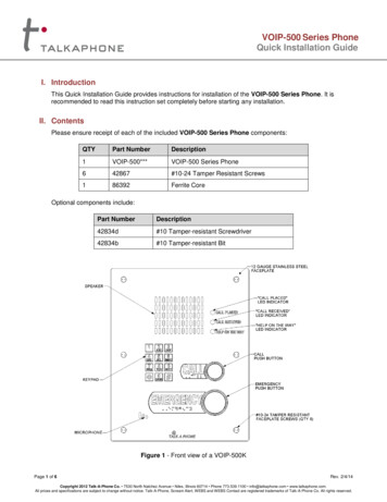
Series 5600PG Preglazable Curtainwall Installation InstructionsSection 4: Horizontal Stacking of Units - Captured System.1. Prior to setting the first unit above, clean the top of the chicken neck area with alcohol and apply a continuous 3/16” diameter bead of sealant above the weather stripon the front side of the chicken neck of the unit below (Figure 13).Figure 14Note: There must be at least 4.5” of clearance between the stack head and thestack sill to avoid interference with the lifting lug/splice bar as the unit is beinginstalled (Figure 14).2. Once the glass planes are flush, lower the unit on to the splice bar, taking care toalign them into the tracks properly. (Figure 15).3. Lower the unit into the proper position relative to the unit below to allow thermalexpansion and floor movement per the contract documents. (Figure 15).At least 4.5” clearanceNote: At the proper spacing the unit may be temporarily shimmed hard on the unit below (while the dead load anchors are being fastened.) These shims must be removedwhen the unit above is securely hung from the dead load anchors.Figure 13Figure 15Align into tracksSealant“Chicken neck area”Joint heightper contractdocumentsRemovetemporaryshim atsplice bar(End view of head for sealant location clarity)EFCO (9‐3‐21)Page 14
Series 5600PG Preglazable Curtainwall Installation InstructionsSection 4: Horizontal Stacking of Units - Captured System, cont.4. Prior to installing the next unit in the row, clean theexterior snap leg of the male split jamb to be assembled with alcohol and then apply a continuous bead ofsealant (Figure 10 page 13) Also, apply a continuousbead of sealant above the weather strip on the frontside of the chicken neck of the unit below. (Figure 13page 14) Figure 16 shows assembled units.Figure 165. Snap units together, lower into position and anchor asdescribed on page 13.Note: Follow this process on all units for each additionalrow.EFCO (9‐3‐21)Page 15
Series 5600PG Preglazable Curtainwall Installation InstructionsSection 4: Horizontal Stacking of Units - Captured System, cont.Sealing of intersection of captured stack joints with HN47 and HN48*Note: At the intersection of four captured units there is a critical joint plug.1. Clean joint with alcohol before inserting mull plugs.HN47 (2)HN48 (2)2. Stack (2) HN47 mull plugs back to back and apply sealant to all surfaces.3. Insert HN47 stack into the joint of the four intersecting units (Figure 17).4. After insertion, apply additional sealant and tool to all contact surfaces(Figure 18).5. A similar situation happens at the condition jamb where two units arehorizontally stacked.6.At this location use (2) HN48 mull plug in the same fashion as above(Figure 19).Figure 17Figure 18Sealant on allcontact surfacesFigure 19Qty 2 HN48 (stacked)Qty 2 HN47 (stacked)EFCO (9‐3‐21)Page 16
Series 5600PG Preglazable Curtainwall Installation InstructionsSection 4: Horizontal Stacking of Units - Captured System, cont.Sealing of intersection of captured stack corner joints with HNG5 & HNG6HNG5 (2)HNG6 (2)*Note: At the intersection of corner units there is a critical joint plug.1. Clean joint with alcohol before inserting mull plugs.2. Stack (2) HNG5 mull plugs face to face and apply sealant to all surfaces.3. Insert HNG5 stack into one side of the corner units (Figure 20).4. After insertion, apply additional sealant and tool to all contact surfaces(Figure 20).5. Repeat the same process with (2) HNG5 plugs on the opposite side of thecorner. (Figure 20).6.Apply sealant to HNG6 similar to HNG5. Stack HNG6 similar to HNG5 andinsert into remaining cavity (Figure 21)7.Seal and tool all intersections between plug-to-mullion and plug-to-plug.Figure 20*Sealant on all contact surfaces**and between stacked plugs*Figure 21Figure 20Qty 2 HNG5 (stacked)EFCO (9‐3‐21)Qty 2 HNG5 (stacked)Qty 2 HNG6 (stacked)Page 17
Series 5600PG Preglazable Curtainwall Installation InstructionsSection 4: Horizontal Stacking of Units - SSG SystemInstallation of SSG units is similar to the stackingsequence and installation method as the capturedunits, with the exception of what is shown on thispage. Refer to pages 15 and 16 for these instructions.Figure 22Figure 23Prior to setting the unit above, complete the following steps in this order.1. Clean all joints with alcohol before applyingsealant:2. Seal the joint between the stack head of bothunits (Figure 22).3. Apply a bed of sealant on the horizontal leg ofthe stack head and up the chicken neck (Figure13) at least 5” long centered on the joint between the units (Figure 23).4. Center HC19 silicone splice sheet over joint.Start by applying vertically on the chicken neck,below the bulb vinyl, and extending out the horizontal leg of the stack head. (Figure 24).Seal joint5”Bed of sealantFigure 24Figure 255. Apply sealant around all edges of the splicesheet and tool smooth (Figure 25).Back sealCon nuousbead ofsealantCon nuousbead ofsealant6. Apply a generous amount of sealant to the gapup the chicken neck and tool to all surfaces,including back seal (Figure 25).7. Apply a continuous bead of sealant above theweather strip on the front side of the chickenneck of the unit below. Marry this sealant to thesealant at the joints in the chicken neck.(Figure 25)8. Install the unit above following the same procedures as shown on the pages for capturedunits.EFCO (9‐3‐21)Splice sheetSeal gapand toolSeal aroundsplice sheetand toolsmoothPage 18
Series 5600PG Preglazable Curtainwall Installation InstructionsSection 4: Horizontal Stacking of Units - SSG System, cont.Figure 269. Insert WV9B stack rain screen seal into the horizontal stack joints. Minimizesplices. If a splice must be made; offset it from a vertical frame joint by a minimum of 12”, seal and butt the ends together.Note: The WV9B should extend past the jamb by a minimum of 1/8”.10. Fill the end with sealant. (Figure 28)Note: Special care must be taken when installing perimeter sealant at this location.The perimeter seal must marry with the WV9B and be carefully tooled into all contactsurfaces at this joint. (See page 24 figure 38.)(Condition not shown for clarity)Figure 27WV9BSilicone splice from previous pageFigure 28WV9B (continuous)Seal endEFCO (9‐3‐21)Page 19
Series 5600PG Preglazable Curtainwall Installation InstructionsSection 4: Horizontal Stacking of Units - SSG System, cont.Installation of SSG units is similar to the stackingsequence and installation method as the capturedunits, with the exception of what is shown on thispage. Refer to pages 15 and 16 for these instructions.*Note: Lifting hanger/ splice bar not shown in figures for clarityFigure 29Figure 30Bed of SealantPrior to setting the unit above, complete the following steps in this order.1. Clean all joints with alcohol before applyingsealant:Bed of SealantSeal joint2. Seal the joint between the stack head of bothunits (Figure 29).3. Apply a bed of sealant on the horizontal leg ofthe stack head and up the chicken neck (Figure13) at least 6” long centered on the joint between the units (Figure 30).4. Center the custom silicone splice sheet (Not ByEFCO) on the corner joint. Start by applyingvertically on the chicken neck, below the bulbvinyl, and extending out the horizontal leg ofthe stack head. (Figure 31).3”3”Figure 31Figure 32Con nuous Beadof Sealant“Strip” Silicone5. Apply sealant around all edges of the splicesheet and tool smooth (Figure 32).6. Apply a generous amount of sealant to the gapup the chicken neck and tool to all surfaces,including back seal. (Figure 32).7. Apply a continuous bead of sealant above theweather strip on the front side of the chickenneck of the unit below. Marry this sealant to thesealant at the joints in the chicken neck.8. Install the unit above following the same procedures as shown on the pages for capturedunits.EFCO (9‐3‐21)Seal gap,and tool.Custom “V”Splice Sheet(1 piece).Seal around splicesheets and seal themtogether. Then toolsmooth.*Note: Lifting hanger/ splice bar not shown in figures for clarityPage 20
Series 5600PG Preglazable Curtainwall Installation InstructionsSection 4: Horizontal Stacking of Units - SSG System, cont.9. Insert continuous WV9B stack rain screen seal into the horizontal stack joints. Minimize splices. If a splice must be made; offset it from a vertical frame joint by a minimum of 12”, seal and butt the ends together.10. WV9B should extend past the corner and “wrap” onto the next unit. (Figure 33)Note: Splice to occur 12” or more from corner stack jointWV9B (con nuous)Figure 33*Splice to occur 12” or more from corner. (Unit above not shown for clarity).EFCO (9‐3‐21)Page 21
Series 5600PG Preglazable Curtainwall Installation InstructionsSection 5: Recommended Perimeter Sealing Placement at typical captured and SSG jambs (Figure 34).Figure 34 Placement at typical captured and SSG sills (Figure 35), head condition similar.Note: It is recommended to perform perimeter sealing prior to installation of perimeter pressure plates.Note: Sealant type and joint width per contract documents. See sealant manufacturer instructions for surface preparation and installation guidelines.Dry line and critical sealant line of systemDry line and critical sealant line of systemBacker rod and primary sealFigure 35Backer rod and primary sealEFCO (9‐3‐21)Dry line and critical sealantline of systemDry line and critical sealant line of systemPage 22
Series 5600PG Preglazable Curtainwall Installation InstructionsSection 5: Recommended Perimeter Sealing - Critical Conditions at Captured System1. Seal across the open joint that is left at the stack horizontals, adjacent to the mull plugcondition. Marry this sealant to the perimeter sealant; tool it to the mullions and the jointplug (Figure 36).2. Seal across the top of the tongues of the split mulls at the head and marry to the perimeter sealant. Take special care to force the sealant into the gap between the tongues(Figure 37).Figure 36Jamb condition at horizontal stack joint(Left jamb shown, right jamb opposite)Note: (Building condition not shown for clarity.)Figure 37face of perimeter sealface of perimeter sealPerimeter sealMarry sealant toplug, and acrosstongue to perimeter seal.Marry sealant toplug, and acrosstongue to perimeter seal.Perimeter sealHead at ver cal split mull jointEFCO (9‐3‐21)Page 23
Series 5600PG Preglazable Curtainwall Installation InstructionsSection 5: Recommended Perimeter Sealing - Critical Conditions at SSG System1. When applying the perimeter seal at the jamb, clean and prep surfacesper sealant manufacturers instructions. Tool sealant around the SSGstack rain screen. Ensure that the WV9B rain screen seal is embeddedinto the perimeter seal. Take special care to ensure that no pinholesare left. This joint is critical (Figure 38).Figure 38Perimeter seal2. When applying the perimeter seal at the head and sill, clean and prepsurfaces per sealant manufacturers instructions. Tool sealant into allthe vertical grooves located in the vertical mullion. Pay special attention to the joint where the male and female split mulls come together.(Figure 39).Note: Head conditions at split vertical is shown, sill condition at split verticaland head and sill condition at jamb verticals are similar (Figure 39).Note: (Building condition not shown for clarity.)Tool sealantaround stackrain screenPerimeter sealface of perimeter sealface of perimeter sealFigure 39Jamb condition at horizontal stack joint(Left jamb shown, right jamb opposite)Tool sealant intovertical groovesHead condition at vertical split mull jointEFCO (9‐3‐21)Page 24
Series 5600PG Preglazable Curtainwall Installation InstructionsSection 6: Captured System Pressure PlatesFigure 401. Remove the exterior gasket from the reel and allow it to relaxand decompress.2. Apply the gaskets to the pressure plates.Note: Gaskets must be cut flush at both ends of the vertical pressure plate except at horizontal stack applications, where the gaskets are to extend 1” beyond the top and be 1/2” short at the bottom.Vertical pressure plates1. Before installing vertical pressure plates, apply a generousamount of sealant to exterior faces of the mull plugs. (Figure40).*Generic pressure plateand gaskets shown.Sealant on frontface of mullNote: The previously installed gaskets (Installed in step 2 above)run through at this area, so all voids must be filled.Horizontal pressure platesNote: Horizontal pressure plates are cut 1/4” shorter than DLO,and this difference must be split on both ends (1/8” per end) ofthe horizontal.1. Cut the gasket 1/2” longer than the pressure plate length andapply the gasket so that 1/4” extends beyond each end of thepressure plate.Note: There must be a 3/16” x 1” weep slot centered 4” from eachend of all horizontal pressure plates, including head and sill pressure plate.Optional weep holes: Drill qty (3), 5/16” diameter weep holesside by side centered 4” from each end of the pressure plate.Locate the centerline of the holes 5/32” above the top of thetongue.EFCO (9‐3‐21)Page 25
Series 5600PG Preglazable Curtainwall Installation InstructionsSection 6: Captured System Pressure Plates, cont.Note: Clean surface with alcohol prior to applyingsealant.Figure 411. Install the vertical pressure plates prior to thehorizontal pressure plates using #12 S.S. hexwasher head sheet metal screws. When usingLD20, screws will have washer under head.2. Locate screws 6” O.C. (4.5” O.C for polyamidepressure plates) and at a maximum of 3” fromthe end of each pressure plate.Note: A screw should always be placed in the verticalpressure plate directly across from each horizontal.This is necessary to create maximum control of pressure on the mullion plugs, which provides the criticalsealing function.Vertical gaskets run throughScrew acrossfrom horizontal3. Torque screws to 40 in-lbs. Once all sides of alite have been clamped down, torque all screwsto 80 in-lbs. When using polyamide pressureplates, recheck this torque prior to installing coversWeepNote: Work from the center outward on the horizontalpressure plates, and from the sill up on the verticalpressure plates.4. Seal all joints between vertical and horizontalpressure plates. This should be done just prior toinstalling the covers so that the sealant doesn'tcure and make the cover difficult to snap on(Figure 41).Seal joint5. Take special care to seal the pressure plate gaskets together at the corners, where they meet.Note: In applications where there are horizontalpressure plates only, the horizontal pressure platescannot span across a vertical split mullion withoutleaving a 1/8” gap to allow movement at each vertical.EFCO (9‐3‐21)WeepPage 26
Series 5600PG Preglazable Curtainwall Insta
Series 5600PG Preglazable Curtainwall Installation Instructions EFCO (9‐3‐21) Page 4 Sec on 1: General Notes and Guidelines, cont. G. SEALANT - All sealant must meet [ASTM C 920, CLASS 50].For the purposes of these instructions, sealant is to be defined as the following: