Transcription
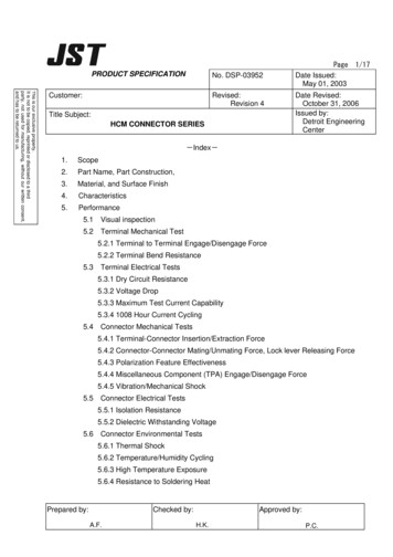
PRODUCT SPECIFICATIONNo. DSP-03952This is our exclusive property.It is not to be copied, reprinted or disclosed to a thirdparty, not used for manufacturing, without our written consent,and has to be returned to us.Customer:Revised:Revision 4Title Subject:HCM CONNECTOR SERIESPageDate Issued:May 01, 2003Date Revised:October 31, 2006Issued by:Detroit EngineeringCenter-Index-1.Scope2.Part Name, Part Construction,3.Material, and Surface Finish4.Characteristics5.Performance5.1Visual inspection5.2Terminal Mechanical Test5.2.1 Terminal to Terminal Engage/Disengage Force5.2.2 Terminal Bend Resistance5.3Terminal Electrical Tests5.3.1 Dry Circuit Resistance5.3.2 Voltage Drop5.3.3 Maximum Test Current Capability5.3.4 1008 Hour Current Cycling5.4Connector Mechanical Tests5.4.1 Terminal-Connector Insertion/Extraction Force5.4.2 Connector-Connector Mating/Unmating Force, Lock lever Releasing Force5.4.3 Polarization Feature Effectiveness5.4.4 Miscellaneous Component (TPA) Engage/Disengage Force5.4.5 Vibration/Mechanical Shock5.5Connector Electrical Tests5.5.1 Isolation Resistance5.5.2 Dielectric Withstanding Voltage5.6Connector Environmental Tests5.6.1 Thermal Shock5.6.2 Temperature/Humidity Cycling5.6.3 High Temperature Exposure5.6.4 Resistance to Soldering HeatChecked by:Prepared by:A.F.Approved by:H.K.1/17P.C.
Page 2/17Modification Record of Product SpecificationCustomer:No,DSP-03952Rev.4Product NameHCM Connector SeriesNoteRev.ReasonPlaceDateEngineer5/ 1/03P.C.5.4.48/ ,0Released15.4.4 TPA Engage/Disengage Force Changed.2345.6.4 Resistance to Soldering Heat,By soldering iron Added2. P/N 3. Material 4. CharacteristicsTemperature Range Changed2. P/N changed2.3.2.4.
Page 3/171.ScopeThis document specifies the product specification and performance information of the HCMconnector series complied with the standard below.TEST STANDARD: SAE/USCAR-2, Performance Standard for Automotive ElectricalConnector Systems Rev.3,Temperature Class: Class 2 (-40 C 100 C)2. Part Name, Part ConstructionTable 2.1 HCM Common Assembly ComponentsNo.123Note:Part NameP/NHCM M-HSG Assy(#)(##)B( )-( )HCM( )( )-( )Male Housing(#) (##)( )-( )HCM( )( )Male PinPS0.64T-( )HCM F-HSG AssyHCM( )PB-( )(##)-( )Female HousingHCM( )P-( )(##)-( )RetainerHCM( )S-(##)-EHCM F-TerminalSHCM-A03T-P025(#) denotes the top entry (B) or Side entry (S)(##) denotes the number of circuits.3. Material, and Surface FinishTable 3.1 Materials, and Surface FinishNo.1Part NameMaterialFinish, Flame ClassMale HousingPBT-G15Black / Natural, UL94-HBMale PinBrassFemale HousingPBTBlack / Natural, UL94-HBRetainerPBTBlue, UL94-HBHCM F-TerminalPhosphor BronzeTin-Plating23Tin-Plating
Page 4/174. CharacteristicsTable 4.1 SPECIFICATIONSItemsSpecificationCurrent Rating5A DC maxVoltage Rating14V DCTemperature RangeInsulation Resistance-40 C 100 CDielectric Withstand Voltage1,000 V/minute ACApplicable CableSAE/AVSS/CAVS: AWG 22-20 (0.3 0.5 sq)20MΩ min
Page 5/17Table 4.2 Summary of Test Results
Page 6/175.PerformancePerformance should satisfy the default value of each test complied with USCAR Standard.(Temperature Class: Class 2)Also evaluation tests shall proceed in the default tolerances and condition unless specified.Default Test TolerancesTemperature: 3 CVoltage: 2%Current: 1%Resistance: 1%Length: 1%Time: 5%Force: 5%Frequency: 5%Distance: 1%Flow Rate: 5%Test Default ConditionsRoom Temperature:23 5 CRelative Humidity:25 75%5.1 Visual InspectionNo defects such as cracks, transformation, and tarnish have ever been noticed.5.2 Terminal Mechanical Tests5.2.1 Terminal Engage/Disengage ForceTest method: Engage and disengage the crimped terminals. The force shall be appliedparallel to the centerlines of the terminals. Then measure the 1st engaging force and the 10thdisengaging force. (Test Speed: 50mm/min)Requirement:Test ItemRequirement1st Engagement1.5 5.5N10th Disengagement1.5 5.5N
Page 7/175.2.2 Terminal Bend ResistanceTest method: Force is to be applied until terminal sample is bent to the angle of 30 5from the centerline. Record the peak force of terminal bend resistance.Samples shall be tested at three different directions as described in figurebelow.Steel Fixture(Test Speed: 50mm/min)Figure 5.2.2 Female Terminal Bend ResistanceRequirement:Test ItemDirectionRequirement0 degree20 AWG90 degree180 degree0 degree22 AWGMin10N90 degree180 degree5.3 Terminal Electrical Tests5.3.1 Dry Circuit ResistanceTest method: Measure and record the resistance between T1 and T2, as shown in thefigure below.Then deduct the 75mm conductor resistance to find the totalconnection dry circuit resistance.Test Current: 100mA(DC)Voltage:20mVMillivolts Leads (30AWG)TT75 3mm
Page 8/17Figure 5.3.1 Dry Circuit Resistance5.3.2Voltage DropTest method: Using the test setup shown below, measure and record the millivolt drop(mVD) readings between test points T1 and T2. Volt drop shall be calculated from theentire resistance after 75mm conductor residence is deducted.Test Current:20 AWG 1.5A20 AWG 2.5AFigure 5.3.2 Measuring Volt Drop5.3.3 Terminal Maximum Test Current CapabilityTest method: Completely mate and unmate each terminal pair a total of 10 times andthen mate them again for testing. Apply the current according to the table below. After thestability of temperature (minimum 15 minutes), measure and record terminal temperaturereading and volt drop. Then record the current reading when the condition satisfies eitherone of each requirement below. 90% of the current reading shall be called TerminalMaximum Current Capability (Note).Note: This current is NOT indicative of the capability of the terminal in an actual vehicleapplication. It is NOT to be used as guidance for any actual application (perUSCAR-2 standard).Requirements: 1.The measured temperature of the terminal exceeds a 55 οC rise.2.The Total Connection Resistance of terminal exceeds 20mΩ.Table 5.3.3-1 Testing of Terminal Maximum Test Current CapabilitySize of Cable20 AWG22 AWGApplied CurrentCurrent Increment5A to 12A1A per testFrom 12A0.5A per test6A to 10A1A per testFrom 10A0.5A per test
Page 9/17Power Supply– CurrentShuntDMV –ThermocouplesTerminal Pair #1Terminal Pair #2MillivoltLeadsTerminal Pair #Non-conductiveMounting PlateFigure 5.3.3-2 Set-Up for Terminal Maximum Current Capability5.3.4 1008 Hour Terminal Current CyclingTest method: Completely mate and unmate each terminal sample a total of 10 times andthen mate again for testing.Set the power supply and a timer to provide 45 minutes 'ON'and 15 minutes 'OFF' at the maximum test current.Cycle for 1008 hours. Measure thecontact resistance before and after the sample test according to 5.3.1 and 5.3.2. Alsomeasure the voltage drop and the terminal temperature rise at max test current at leastonce daily.Requirement:Dry Circuit ResistanceTest ItemInitialPostRequirementMax 20mΩVoltage DropTest ItemInitialPostRequirementMax 20 mΩTemperature RiseTest ItemRequirementTemperatureMax 55 οCRise5.4 Connector Mechanical Tests5.4.1 Terminal-Connector Insertion/Extraction ForceTest Method: Record the force required to insert the terminals (one terminal at a time)into the connector and to extract them out of the connector.mm/min maximum shall be applied.A test speed of 50
Page 10/17Requirement:Test ItemInitial Insertion forceTest Condition(20 AWG)(22 AWG)Initial w/o TPARequirement15N Max30N MinInitial w/ TPAPost 95-98% humidityExtraction Force(20AWG)75N Minat 40 C for 6 hoursPost Temp. / Humid.CyclingPost High48 N MinTemperature5.4.2 Connector-Connector Mating/Un-mating Force, Lock lever Releasing forceTest method: Mate and un-mate crimped Female-terminal (outfitting housing) withmale header on the parallel line to the centerline. Then measure the initial matingforce, un-mating force with/without primary lock, and disengaging primary lock force.(Test speed: 50mm/min)Requirement:Test ItemTest ConditionRequirementMating Force--75N MaxW/ Fully AssembledUnmating ForcePrimary LockReleasing ForceConnector110N Minw/o Primary lock75N Max--70N Max *Note: * indicates that criteria are per HCM connector design specifications5.4.3 Polarization Feature EffectivenessTest method: Orient the female housing 180 degree with respect to the securely fixedmale housing.Engage Female housing halves to the Male header at a uniform rateof 50 mm/min until the force of 220N is applied.
Page 11/17Requirement:Test ItemApplied ForcePolarization FeatureResistance220N MinResult1. Not be inserted2. No pin deformed5.4.4 TPA Engage/Disengage ForceTest Method: Measure TPA insertion force to Female housing and TPA extraction forcefrom Female housing. (Test speed: 50mm/min)Requirement:Test ItemRequirementTPA Insertion Force 10N and 30N*TPA Extraction Force 15N and 30NNote: * indicates that criteria are per HCM connector design specifications.5.4.5 Vibration/Mechanical Shock TestTest method: Test method: Serially connected connector samples shall be mounted on afixture as shown in the figure below.Apply the mechanical shock and vibration requirementshown in Figure 5.4.5-1 below, and monitor if the resistor current drops below 95mA for morethan 1 microsecond for current continuity. In addition to this, measure the contact resistancebefore and after the test.Mechanical Shock: 10 times Half SIN Wave (10 mSec duration at 35Gs force) in eachof the three axis.
Page 12/17Table 5.4.5-1 Vibration Profile (Not Coupled to Engine)Vibration ProfileFrequencyPower Spectral Density(Hz)(g2 0.00.01180230.00.000321000.00.00002Grms 1.81DC Power SupplyContinuity Totalizer / AnalyzerResistor 120 ohms 1% 2watts19 6 Vibration PlateMounting BracketTrunion BaseFigure 5.4.5-2 Setting of Vibration Test1.1.01.001.0001.00001110100Figure 5.4.5-3 Vibration Profile1000
Page 13/17Requirement:Current ContinuityTest ItemEntire TestingRequirementNo DiscontinuityDry Circuit ResistanceTest ItemInitialPostRequirementMax 20mΩVoltage DropTest ItemInitialPostRequirementMax 20mΩ5.5 Connector Electrical Tests5.5.1 Isolation ResistanceTest method: Apply DC500V to measure the resistance between the adjacentterminals (no solder for Male-Pin) in fully assembled connector.Requirement:Test ItemIsolationResistanceRequirement20 MΩ Min
Page 14/175.5.2 Dielectric Withstanding VoltageTest method: Test voltage specified below shall be applied between adjacent pins of amated specimen (connector shall not be soldered) for one minute.Test ItemDielectricTest voltageWithstandingAC 1,000 VVoltageRequirementNo breakdown norflash-over5.6 Connector Environmental Tests5.6.1 Thermal ShockTest method: Completely mate and unmate connector samples a total of 10 times and matethem again for testing. Place those samples in a chamber for 30minutes at -40ο C andanother 30 minutes at 100ο C. Repeat the cycle for 100 times. Measure the currentresistance before and after the test, and monitor if the resistor current drops below 95mA formore than 1 microsecond for current continuity.Requirement:Current ContinuityTest ItemEntire TestingRequirementNo DiscontinuityDry Circuit ResistanceTest ItemInitialPostRequirementMax 20mΩVoltage DropTest ItemInitialPostRequirementMax 20mΩ
Page 15/175.6.2Temperature/Humidity CyclingTest method: Completely mate and unmate connector samples a total of 10 times and matethem again for testing. Place those samples in a chamber for 40 cycles of as described inthe figure below.Measure terminal extraction force after the test, and monitor if theresistor current drops below 95mA for more than 1 microsecond for current continuity.NOTE: Test Parameters must remain within shaded regionsFigure 5.6.2 Temperature/Humidity Cycling TestRequirement:Current ContinuityTest ItemEntire TestingRequirementNo DiscontinuityDry Circuit ResistanceTest ItemInitialPostRequirementMax 20mΩ
Page 16/17Voltage DropTest ItemInitialPostRequirementMax 20mΩNotes: For the result of terminal extraction force after the Temperature/HumidityCycling test, refer to 5.4.1.5.6.3 High Temperature ExposureTest method: Completely mate and unmate connector samples a total of 10 timesand mate them again for testing. Place the samples in a chamber for 1008 hours at100 C. Then measure initial/post resistance and voltage drop.Test Spec:Dry Circuit ResistanceTest ItemInitialPostRequirementMax 20mΩVoltage DropTest ItemInitialPostRequirementMax 20mΩNotes: For the result of terminal extraction force after the High TemperatureExposure test, refer to 5.4.1.5.6.4. Resistance to Soldering HeatTest method: The specimen mounted on a PCB shall be soldered bysoldering iron of the following conditions. Flux and solder shall be used.Requirement: There shall be no deformation nor damage which may affectthe connector performance.
Page 17/17[By Dip soldering]Temperature of the tip:Period of soldering:Apply PCB:260 5 C5 0.5 seconds1.6mm/Through Hole[By soldering iron]Temperature of the tip: 350 10 CSoldering:3 seconds Max.Apply PCB:1.6mm/Through HoleNote: No abnormal load such as lateral load shall be applied to the pinssoldering.Test ItemResistance to Soldering HeatRequirementNo deformation nor damage whichmay affectThe connector performance.
SAE/AVSS/CAVS: AWG 22-20 (0.3 0.5 sq) Page 5/17. Table 4.2 Summary of Test Results . Page 6/17 Default Test T. 5. Performance . Performance should satisfy the default value of each test complied with USCAR Standard. (Temperature Class: Class 2) Also evaluation tests shall proceed in the default tolerances and condition unless specified. olerances Temperature: 3 C . Voltage: 2% . Current .

