Transcription
Fan Coil UnitAquaris SilentFerdinand Schad KGSteigstraße 25-27D-78600 KolbingenTelephone 49 (0) 74 63 - 980 - 0Fax 49 (0) 74 63 - 980 - 200info@schako.dewww.schako.de
Fan Coil Unit Aquaris SilentContentsDescription . 3Advantages . 3Description of the equipment . 3Base unit . 3Housing . 3Heat exchanger . 3Condensate pan . 4Motorised fan . 4Filter . 4Accessories . 4Models, dimensions and weights . 5Dimensions and weights . 5Models . 6Electric connections . 7Quick selection diagrams . 11SP series . 11EC series . 12Technical data . 13Nominal capacity 2-pipe systems . 13Nominal capacity 4-pipe systems . 15Sound power level . 17Characteristics with ceiling diffuser DBB and ventilation grille Ib 1 . 18Sound pressure level (LP) . 19Accessories . 20Plenum boxes for supply (-PZ) and return air (-PA) . 20Connecting the air ducts . 22Connection piece (-ÜS-F) . 23lb 1 ventilation grille . 24Ceiling diffuser DBB . 25Electric heating register (-BE) . 26Device casing . 28Additional valve condensate pan (-KW) . 28Valve kit . 28Condensate pump (-KP) . 29Control units . 30Valves and actuators . 33Installation . 35Maintenance . 35Legend . 36Order details . 37Specification texts . 38Selection program for a quick and accurate design . 3811/01 - 2Construction subject to change.Version: 05.04.2013No return possible!
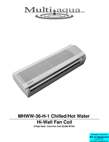
Fan Coil Unit Aquaris SilentDescriptionDescription of the equipmentThe Aquaris Silent fan coil units are air-conditioners that are especially designed for the decentralised use, for heating or cooling with circulating air.The fan coil units guide the air to be treated through the heat exchanger where it can be heated or cooled in a particularly energyefficient way. They are used to bring the air quickly to the desiredtemperature and require only small heating or cooling surfaces.The optimised heat transmission allow lower supply temperatures during heating. And higher supply temperatures duringcooling. This minimises the line losses and saves energy on theway from the boiler or cold water generator to the end device.With different fan speeds or continuous control and valves to influence the flow rate, the device power can be controlled in aflexible way and adapted to nearly all conditions.Starting from the ambition to provide maximum adaptation tothe architectural situation of the room to be air-conditioned, thefan coils are produced in different models - ranging from unitsto be installed in false ceilings and floors (horizontal model) tounits for visible mounting with device casing (vertical and horizontal models).Base unitThe base unit consists of a housing made of galvanised steelwith thermal and acoustic insulation. A motorised fan, one ortwo heat exchangers, a filter and a condensate pan are integrated in the unit.Characteristics- Air throughput from 160 to 1850 m3/h- Cooling capacity: from 1 to 8.3 kWa Heat exchanger- Heating capacity: from 1.25 to 11 kWb Housing- Static pressure: up to 70 Pac Motorised fand Filtere Condensate panAdvantages- Flexible assembly and installation versionsHousing- High cooling and heating capacitiesThe housing of the device consists of profiles and covers madeof galvanised sheet steel having a 6 mm thick insulation.- Control technology adapted to any demand- Low noise generation or reduced sound pressure- Energy-efficient, decentralised air conditioning- Solid compact design- Easy mounting and maintenance- Attractive appearance (unit plus housing)Heat exchangerThe heat exchanger unitcan consist of a single register of 3 rows for coolingand heating operation (forconnection to 2 pipelines)or of two registers of 3 1rows (for connection to 4pipelines).The registers were developed for use with water or a water/glycol mixture and consist ofcopper pipes, aluminium ribs, a manual ventilation and drainagesystem and a frame made of galvanised sheet steel.The length of the register depends on the required performance.The water connections can be attached to the register either onthe left- or right-hand side.Optionally, an electric heating register can be used to supportthe heating mode.11/01 - 3Construction subject to change.Version: 05.04.2013No return possible!
Fan Coil Unit Aquaris SilentCondensate panThe condensate pan can bemounted horizontally or vertically and serves for the collection of the condensatewater below the cooling register. The pan is made of galvanised steel and has athermal insulation (polyethylene with a thickness of 3mm) to avoid the formation of condensation water.The condensation water outlet is located on the same side as thehydraulic connections and can be connected to the on-site drainsystem.Motorised fanThe motorised fan consistsof double-sided intake-operation, dynamically balancedcentrifugal blowers with forward curved blades and direct drive.The fan motors are designedas AC (SP series) or highly efficient EC motors (EC series) andare equipped with maintenance-free friction bearings for a longservice life.For the AC fan motor, 6 steps are made available by a step transformer. The EC fan can be activated with 0-10 V and is infinitelyvariable.The housing and the fan wheel are made of plastic and are optimised for the lowest possible sound pressure.FilterThe air filter of filter class G2and G3 (according to the order) consists of a syntheticfabric on a plastic frame. Thefilters are attached withholding clips and can be dismounted without requiringtools. Moreover, they are distinguished by simple maintenance(washing or compressed air).AccessoriesOptionally, depending on customer request and installationspecific requirements or in order to achieve increased performance and optimum operating characteristics, different additionalcomponents can be integrated, such as plenum boxes for supply and return air, electrical heating registers, flexible connections, connection frames, housings, valve kit, additionalcondensate pan, condensate pump, SCHAKO Ib 1 ventilationgrilles and SCHAKO DBB ceiling diffusers. SCHAKO offers anextensive product range of control equipment.11/01 - 4Construction subject to change.Version: 05.04.2013No return possible!
Fan Coil Unit Aquaris SilentModels, dimensions and weightsDimensions and weightsBase unit- Left side view (air flow direction)- The electric connection of the standardmodel is located opposite to the hydraulicconnection side.Housing (optional accessories)NW10 / 11Dimensions (mm)Weight (kg)Water capacity of the registers (l)L1L2L3L4L5G1G23 rows1 row69767064564975514201.20.320 / 2191288586086497020281.60.430 / 311247122011951199130525362,30.640 / 411352132513001304141032462.50.750 / 511597157015451549165535493.00.9A cold water outlet (cylindrical internal thread, EN 10226-1 Rp 1/2)B cold water outlet (cylindrical internal thread, EN 10226-1 Rp 1/2)C cold water outlet (cylindrical internal thread, EN 10226-1 Rp 1/2)D cold water outlet (cylindrical internal thread, EN 10226-1 Rp 1/2)E Condensate drain DN16 mm (external)G1 Weight of the base unitG2 Weight of the base unit, including device casingTo avoid deposits and corrosion, the water qualityfor filling the registers must meet the requirementsaccording to the regulations VDI 2035 and VDI50930.11/01 - 5Construction subject to change.Version: 05.04.2013No return possible!
Fan Coil Unit Aquaris SilentModelsHorizontal installation with hydraulic connection on the right-H.-RHorizontal installation with hydraulic connection on the left-H.-LVertical installation with hydraulic connection on the right-V.-RVertical installation with hydraulic connection on the left-V.-LVertical modelThis unit was especially developed for wall mounting.Horizontal modelIts compact size and low height make the Aquaris Silent fan coilunit an ideal solution for installation in false ceilings and floors,also allowing an open installation suspended from the ceiling.Unit installed in false ceiling:11/01 - 6Construction subject to change.Version: 05.04.2013No return possible!
Fan Coil Unit Aquaris SilentElectric connectionsElectric connection diagram (SP series)Cooling valve1223NCondensate pumpPENAlarm8 A, 250 VLNCThermo contactStage 1Connection fan speed1CThermo contactHeating valve3Connect the fan coil unit to the earthing cable.Interrupt the power supply, before carrying out anyelectrical connection work.SCHAKO cannot be held liable for faulty electricalconnections or incorrectly dimensioned connecting cables.PEStage 2Stage 3Stage 4Stage 5Stage 62PENCNCAlarm8.0 A 250VLCondensate pump30 - 10 Vdc1LOn-siteINPUT 0-10 Vdc: GND-VCT3PEOUTPUT 10 Vdc: GND-10V2Heating valve1Cooling valveElectric connection diagram (EC series)N10 VVCTGND -10 V10 V10 VVCTGNDVCTGND0V11/01 - 7Construction subject to change.Version: 05.04.2013No return possible!
Fan Coil Unit Aquaris SilentWiring thermo contact, overload protection, operational and fault message (SP series)ON-SITERoomcontrollerYellowGreenWhite (*)White ediummin.Yellow / GreenWiring thermo contact, overload protection, operational and fault message (EC series)N LON-SITERoomcontrollerConnection depending on the signal typeYellow / GreenBrownAquaris-ECBlueRedBlueBlack10 VVCTGNDWhite (*) potential-free thermo contact as overload protection for motor, to be provided on-site11/01 - 8Construction subject to change.Version: 05.04.2013No return possible!
Fan Coil Unit Aquaris SilentCircuit diagram (with thermo contact)1 speed switch 2 or more fan coils (SP series)ON-SITESpeed switchYellowGreenYellowGreenWhite (*)White (*)BlueBrownBlackGreyPurpleOrangeRedYellow/ GreenWhite (*)White (*)BlueBrownBlackGreyPurpleOrangeRedYellow/ Greenmax.mediummin.max.mediummin.White (*) potential-free thermo contact as overload protection for motor, to be provided on-site11/01 - 9Construction subject to change.Version: 05.04.2013No return possible!
Fan Coil Unit Aquaris SilentCircuit diagram (with thermo contact)1 speed switch 2 or more fan coils (EC series)ON-SITEN LRoomcontrollerYellow / GreenBrownRedBlueBlackConnection depending on the signal typeAquaris-ECBlue10 VVCTGNDYellow / GreenBrownAquaris-ECBlueRedBlueBlack10 VVCTGND11/01 - 10Construction subject to change.Version: 05.04.2013No return possible!
Fan Coil Unit Aquaris SilentQuick selection diagramsSP seriesTotal heating capacity (2-pipe system) (1) Total cooling capacity (2-pipe system) (1)(see conditions on Page 13)(see conditions on Page ,53,02,52,01,51,08,58,07,57,06,55,55,0Q (kW)Qges 13NW403413503513Total cooling capacity (4-pipe system) (1)(see conditions on Page ,52,01,51,0414504514Q (kW)Qges (kW)6,04,54,03,53,02,52,01,51,0(1)113Total heating capacity (4-pipe system) (1)(see conditions on Page 204214304314NW404cooling and heating capacities at speed level 1-611/01 - 11Construction subject to change.Version: 05.04.2013No return possible!
Fan Coil Unit Aquaris SilentEC 06,05,55,55,05,0Q (kW)Qges (kW)Total heating capacity (2-pipe system) (2) Total cooling capacity (2-pipe system) (2)(see conditions on Page 14)(see conditions on Page 3NW4030,5503Total cooling capacity (4-pipe system) (2)(see conditions on Page 04304NW404303NW4035034,03,51042034,53,50,5103Total heating capacity (4-pipe system) (2)(see conditions on Page 16)Q (kW)Qges (kW)4,03,50,5(2)4,50,5504104204304NW404504cooling and heating capacities at 1-10V11/01 - 12Construction subject to change.Version: 05.04.2013No return possible!
Fan Coil Unit Aquaris SilentTechnical dataNominal capacity 2-pipe systemsSP seriesnEK (230V 50 Hz)1-max.V3(m /h) x.Pa WH3-medium(kPa)(3)5-min.1-max.TAK3-medium( C)(2)5-min.1-max.TAH3-medium( 150,96 57,4039,99 47,3019,33 23,8041,52 46,7732,58 38,5315,74 0128,9 141,5106,1 ,4121,50,930,630,49Calculations with filter G2(1) Measured at 0 Pa of available pressure(2) Air inlet temperature 27 C, water inlet temperature 7 C, temperature difference 5 C(3) Air inlet temperature 20 C, water inlet temperature 50 C, same water throughput as in cooling (2)11/01 - 13Construction subject to change.Version: 05.04.2013No return possible!
Fan Coil Unit Aquaris SilentEC 2)Q(kW)(3)VW(l/h)(2)PaWK(kPa)(2)Pa WH(kPa)(3)TAK( C)(2)TAH( C)(3)rFAK(%)rFAH(%)W(W)SFP[W/ lations with filter G2(1) Measured at 0 Pa of available pressure(2) Air inlet temperature 27 C, water inlet temperature 7 C, temperature difference 5 C(3) Air intake temperature 20 C, water intake temperature 50 C, same water throughput as in cooling (2)11/01 - 14Construction subject to change.Version: 05.04.2013No return possible!
Fan Coil Unit Aquaris SilentNominal capacity 4-pipe systemsSP seriesn101-max.3803-medium 41-max.2,09Qges3-medium 1,59(kW)(2)5-min.1,061-max.1,61Qs3-medium 1,2(kW)(2)5-min.0,781-max.2,12Q3-medium 1,67(kW)(3)5-min.1,181-max.360VWK3-medium 274(l/h)(2)5-min.1821-max.182VWH3-medium 143(l/h)(3)5-min.1021-max.17,79PaWK3-medium 11,01(kPa)(2)5-min.5,371-max.7,39PaWH3-medium 4,84(kPa)(3)5-min.2,641-max.14,2TAK3-medium 13,2( C)(2)5-min.12,11-max.36,5TAH3-medium 38,6( C)(3)5-min.41,91-max.88,1rFAK3-medium 91,0(%)5-min.94,41-max.19,1rFAH3-medium 17,0(%)5-min.14,31-max.58,8W3-medium 40,0(W)5-min.22,11-max.0,26I3-medium 0,17(A)5-min.0,10EK (230V 50 alculations with filter G2(1) Measured at 0 Pa of available pressure(2) Air inlet temperature 27 C, water inlet temperature 7 C, temperature difference 5 C(3) Air inlet temperature 20 C, water inlet temperature 70 C, temperature difference 10 C11/01 - 15Construction subject to change.Version: 05.04.2013No return possible!
Fan Coil Unit Aquaris SilentEC AK( C)(2)TAH( C)(3)rFAK(%)rFAH(%)W(W)SFP[W/ lculations with filter G2(1) Measured at 0 Pa of available pressure(2) Air inlet temperature 27 C, water inlet temperature 7 C, temperature difference 5 C(3) Air inlet temperature 20 C, water inlet temperature 70 C, temperature difference 10 C11/01 - 16Construction subject to change.Version: 05.04.2013No return possible!
Fan Coil Unit Aquaris SilentSound power level2- and 4-pipe systems (EC 763,153,144,065,057,250,41020304050LWA ,938,857,150,143,4fm (Hz)nLW [dB/ Okt]250LWA [dB(A)]3180003040002120002010001150010250NW125LW [dB/ Okt]1252- and 4-pipe systems (SP t(V)10621062106210621062fm (Hz)Measured sound power level in accordance with ISO standard 3744Measured sound power level in accordance with ISO standard 374411/01 - 17Construction subject to change.Version: 05.04.2013No return possible!
Fan Coil Unit Aquaris SilentCharacteristics with ceiling diffuser DBB and ventilation grille Ib 12-conductor 49011809357,236,155,195,734,804,004-pipe 5,155,664,753,967,126,295,40Calculations with filter G2(2) air inlet dry bulb temperature of 27 C and wet bulb temperature of 19 C, water inlet temperature of 7 C,Temperature difference 5 C(3) Air inlet temperature 20 C, water inlet temperature 70 C, temperature difference 10 CCorrection factors for Aquaris Silent with lb 1 ventilation grilleSystem2-pipe4-pipeCorrection factors0,960,97Correction factors for cooling capacityWater intake/water outlet temperature ( C)Air intake temperature 27 CAir intake temperature 26 930,840,740,910,930,840,760,70Correction factors for heating capacity90/701,32Water intake/water outlet temperature ( C)70/6070/5060/4010,840,6040/300,3011/01 - 18Construction subject to change.Version: 05.04.2013No return possible!
Fan Coil Unit Aquaris SilentSound pressure level (LP)Q valueS αR ------------1–α4QL P L W 10 log -----------------------2- ---- log ( N ) 0, 51010R4 π rQ Direction of noise sourcer Distance from noise source (m)R Room constantS Sum of the room surface areasαα Average value of the room absorption coefficient0,03Minimum valueN Number of fan coil units in the room0,05Factories, indoor swimming pools, large churches, classroo
Ferdinand Schad KG Steigstraße 25-27 D-78600 Kolbingen Telephone 49 (0) 74 63 - 980 - 0 Fax 49 (0) 74 63 - 980 - 200 info@schako.de www.schako.de