Transcription
INSTALLATION INSTRUCTIONSFan CoilsFVM4X “B” SeriesThese instructions must be read and understood completely before attempting installation.Safety Labeling and Signal WordsDANGER, WARNING, CAUTION, andNOTEThe signal words DANGER, WARNING, CAUTION, and NOTE are used to identify levels of hazard seriousness. The signal word DANGER is onlyused on product labels to signify an immediate hazard. The signal words WARNING, CAUTION, andNOTE will be used on product labels and throughout this manual and other manuals that may applyto the product.DANGER - Immediate hazards which will result insevere personal injury or death.WARNING - Hazards or unsafe practices whichcould result in severe personal injury or death.CAUTION - Hazards or unsafe practices whichmay result in minor personal injury or product orproperty damage.Signal Words in ManualsThe signal word WARNING is used throughout thismanual in the following manner:!WARNINGWARNINGThe signal word CAUTION is used throughout thismanual in the following manner:!CAUTIONSignal Words on Product LabelingSignal words are used in combination with colorsand/or pictures on product labels.NOTE - Used to highlight suggestions which willresult in enhanced installation, reliability, or operation.TABLE OF CONTENTSIntroduction . . . . . . . . . . . . . . . . . . . . . . . . . . . . . . . . . . . . 2Location . . . . . . . . . . . . . . . . . . . . . . . . . . . . . . . . . . . . . . . 2Heater Packages . . . . . . . . . . . . . . . . . . . . . . . . . . . . . . . 3Position Unit . . . . . . . . . . . . . . . . . . . . . . . . . . . . . . . . 3 - 7Air Ducts . . . . . . . . . . . . . . . . . . . . . . . . . . . . . . . . . . . . . . 7Electrical Connections . . . . . . . . . . . . . . . . . . . . . . 8 - 10Refrigerant Tubing . . . . . . . . . . . . . . . . . . . . . . . . . . . . . 10Refrigerant Metering Device . . . . . . . . . . . . . . . . . . . . 10Condensate Drains . . . . . . . . . . . . . . . . . . . . . . . . . . . . 11Blower Motor - CFM . . . . . . . . . . . . . . . . . . . . . . . 12 - 13Accessories . . . . . . . . . . . . . . . . . . . . . . . . . . . . . . . . . . 14Sequence of Operation . . . . . . . . . . . . . . . . . . . . . . . . . 15Wiring Diagram . . . . . . . . . . . . . . . . . . . . . . . . . . . . . . . 16Fan Coil Airflow . . . . . . . . . . . . . . . . . . . . . . . . . . . 17 - 19ECM Motor and Control . . . . . . . . . . . . . . . . . . . . . . . . 19Troubleshooting ECM Motor and Controls . . . . 19 - 21Start- up Procedure . . . . . . . . . . . . . . . . . . . . . . . . . . . . 22Care and Maintenance . . . . . . . . . . . . . . . . . . . . . . . . . 22R- 410A Quick Reference Guide . . . . . . . . . . . . . . . . . 23Specifications are subject to change without notice!WARNINGDEATH, PERSONAL INJURY, AND/OR PROPERTYDAMAGE HAZARDFailure to carefully read and follow this warningcould result in equipment malfunction, propertydamage, personal injury and/or death.Installation or repairs made by unqualified persons could result in equipment malfunction, property damage, personal injury and/or death.The information contained in this manual is intended for use by a qualified service technician familiar with safety procedures and equipped withthe proper tools and test instruments.Follow all safety codes. Wear safety glasses, protective clothing, and work gloves. Use quenchingcloth for brazing operations. Have fire extinguisher available.Installation must conform with local buildingcodes and with the National Electrical CodeNFPA70 current edition.In Canada, refer to current editions of the Canadian electrical code CSA22.1.496 01 5002 034/20/18
INSTALLATION INSTRUCTIONSFan Coils: FVM4XINTRODUCTIONModels FVM4X are designed for maximum flexibility andcan be used for upflow, horizontal left or right, anddownflow applications (accessory kit required fordownflow or horizontal right).These units are designed to meet cabinet air leakage ofless than 2% at 0.5 inches W.C. and cabinet air leakageless than 1.4% at 0.5 inches W.C. when tested inaccordance with ASHRAE 193 standard. Because of this,the units need special attention in the condensate panand drain connection area and when brazing tubing.Four fan coil sizes will combine with various outdoor unitsizes to offer systems ranging from 1½ - 5 tons (18,000- 60,000 BTUH) nominal cooling capacity.All models have a factory installed and appropriatelysized hard shut- off TXV metering device.Factory- authorized, field- installed electric heaterpackages are available in sizes 5 kW through 30 kW. SeeProduct Specification literature for available accessorykits.LOCATIONSelect the best position which suits the installation siteconditions. The location should provide adequatestructural support, space in the front of the unit for serviceaccess, clearance for return air and supply ductconnections, space for refrigerant piping connections andcondensate drain line connections. If heaters are beinginstalled make sure adequate clearance is maintainedfrom supply duct work. Refer to Clearances below.Nuisance sweating may occur if the unit is installed in ahigh humidity environment with low airflow. On theseinstallations a wrap of 2 (51 mm) fiberglass insulationwith a vapor barrier is recommended.NOTE: Internal filter can be accessed from separate filterdoor. If the filter can NOT be easily accessed, a remotefilter is recommended. Refer to ACCA Manual D forremote filter sizing.Refer to Table 1. Install the fan coil with theaccompanying kit to ensure compliance with low leakrequirements of less than 2% cabinet leakage rate at0.5 inches W.C. and 1.4% cabinet leakage rate at 0.5inches W.C. when tested in accordance with ASHRAE193 standard.NOTE: Units that require a kit to meet low leakrequirements have a gasket kit automatically includedwith shipment.Table 1 – Gasket Kit Requirement2Unit SizeKit Needed?024Yes036Yes048Yes060Yes!WARNINGFIRE HAZARDFailure to maintain proper clearances could resultin personal injury, death, and/or property damage.When heaters are installed, maintain clearancesfrom combustible materials as specified on unitrating plate. Do not use plastic lined or combustible flexible ducting within 36” (914.4) of the supply end of the fan coil.REQUIRED CLEARANCES - ALL MODELS (inches)All SidesNoHeatersFrom Supply DuctAll SidesWithFrom First 3 feet of Supply Duct to CombustiblesHeatersFrom Supply Duct to Combustibles after 3 feet00010496 01 5002 03
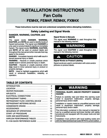
INSTALLATION INSTRUCTIONSFan Coils: FVM4XHEATER PACKAGESFactory approved, field installed, UL listed heaterpackages are available from the equipment supplier. Seeunit rating plate for a list of factory approved heaters.Heaters that are not factory approved could causedamage which would not be covered under theequipment warranty.POSITION UNITUnit can stand or lie on floor, or hang from ceiling or wall.Allow space for wiring, piping, and servicing unit.CAUTION!If return air is to be ducted through a floor, install duct flushwith floor. Set unit on floor over opening.Side return is a field option on slope coil models. Cutopening per dimensions shown in Figure 2. Afield- supplied bottom closure is required.PROPERTY DAMAGE HAZARDFailure to follow this caution may result in property damage.A field fabricated auxiliary drain pan, with a separate drain is REQUIRED for all installations over afinished living space or in any area that may bedamaged by overflow from a restricted main drainpan. In some localities, local codes require an auxiliary drain pan for ANY horizontal installation.Figure 2A. UPFLOW INSTALLATION!CAUTIONFailure to follow this caution may result in personalinjury.Sheet metal parts may have sharp edges or burrs.Use care and wear appropriate protective clothingand gloves when handling parts.Slope Coil Unit in Upflow ApplicationPOWER ENTRYOPTIONSFIELD SUPPLIEDSUPPLY DUCTLOW VOLTENTRYOPTIONSFRONT SERVICE CLEARANCE24 - 48 models 21”(533.4)60 model 24”(609.6)SLOPE COIL UNITMODEL SIZEAA- COILUNITSUPFLOW/DOWNFLOWSECONDARY DRAINUPFLOW/DOWNFLOWPRIMARY DRAIN3619" (482.6)1½”(38.1)19”(482.6)2½”(63.5)AFIELD MODIFIEDSIDE RETURNLOCATION FORSLOPE COILUNITS ONLYUPFLOW/DOWNFLOWSECONDARY DRAINUPFLOW/DOWNFLOWPRIMARY DRAIN496 01 5002 03FIELD SUPPLIEDRETURN PLENUM3
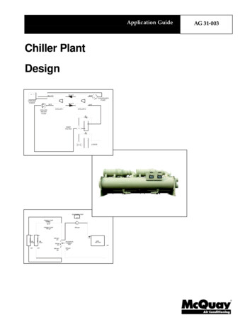
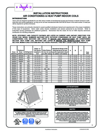
INSTALLATION INSTRUCTIONSFigure 3Fan Coils: FVM4XModular Unit AssemblyB. MODULAR UNITSFVM fan coil sizes 4800 and 6000 are two- piece modularunits. This allows for modular units to be disassembledand components moved separately to installation area forreassembly. This process accommodates small scuttleholes and limiting entrances to installation sites (refer toFigure 3).C. HORIZONTAL INSTALLATIONBLOWER BOXUnit must NOT be installed with access panels facing upor down. Access panels must only face to the side.2 SCREWSFVM models are factory built for horizontal left installation(refer to Figure 4 and Figure 5). They can be fieldconverted to horizontal right (accessory Gasket Kitrequired - EBAC01GSK).2 SCREWSNOTE: When suspending unit from ceiling, dimples incasing indicate suitable location of screws for mountingmetal support straps (refer to Figure 4).REAR CORNERBRACKET2 SCREWSCOIL BOXFigure 4NOTE: For optimum condensate drainage performancein horizontal installations, unit should be leveled along itslength and width.Slope Coil In Horizontal Left Application (FVM factory configuration)A- COILHORIZONTAL YDRAINFRONT SERVICE CLEARANCE(FULL FACE OF UNIT)24 - 48 models 21” (533.4)60 model 24”(609.6)SECONDARYDRAINLOW VOLTENTRYOPTIONS1¾” (44.45)FILTER ACCESSCLEARANCEPOWERENTRYOPTIONS4PRIMARYDRAIN496 01 5002 03
INSTALLATION INSTRUCTIONSFigure 5Fan Coils: FVM4XA- Coil in Horizontal Left Application (FVM factory configuration)ACOILBRACKETFACTORY SHIPPEDHORIZONTAL LEFTAPPLICATIONCOILSUPPORTRAILBCDRAIN PANSUPPORTBRACKETCOILBRACKETHORIZONTALDRAIN PANPRIMARY DRAINHORIZONTAL LEFTAIR SEALASSEMBLYREFRIGERANTCONNECTIONSHorizontal Right Conversion of Units With SlopeCoils1. Remove blower and coil access panel and fittingpanel (refer to Figure 6).2. Remove coil mounting screw securing coilassembly to right side casing flange.3. Remove coil assembly.SECONDARY DRAINHORIZONTAL LEFT4. Lay fan coil unit on its right side and reinstall coilassembly with condensate pan down (refer toFigure 6).5. Attach coil to casing flange using coil mountingscrew previously removed.6. Make sure the pan cap in the fitting door is properlyseated on the fitting door to retain the low air leakrating of the unit.Horizontal Right Conversion Applications - Slope CoilFigure 6COIL MOUNTINGSCREWBLOWERASSEMBLYCOIL SUPPORT RAILSLOPE COILDRAINPANREFRIGERANTCONNECTIONSPRIMARY DRAINSECONDARY DRAIN496 01 5002 035
INSTALLATION INSTRUCTIONSFan Coils: FVM4X7. Add gaskets from the Gasket Accessory Kit EBAC01GSK.Figure 78. Align holes with tubing connections andcondensate pan connections, and reinstall accesspanels and fitting panel. Make sure liquid andsuction tube grommets are in place to prevent airleaks and cabinet sweating.Conversion for Horizontal Right Applications - A- CoilAREFRIGERANTCONNECTIONSAIR AILCOILBRACKETBCDRAIN TALDRAIN PANPRIAMRY DRAINHORIZONTAL RIGHTSECONDARY DRAINHORIZONTAL RIGHTHorizontal Right Conversion of Units With A- Coils1. Remove blower and coil access panel and fittingpanel (refer to Figure 7).2. Remove metal clip securing fitting panel tocondensate pan. Remove fitting panel.3. Remove two (2) snap- in clips securing A- coil inunit.4. Slide coil and pan assembly out of unit.5. Remove horizontal drain pan support bracket fromcoil support rail on left side of unit and reinstall oncoil support rail on right side of unit.6. Convert air- seal assembly for horizontal right.a. Remove air- seal assembly from coil by removingfour (4) screws (refer to Figure 7).b. Remove air splitter (B) from coil seal assembly byremoving three (3) screws. (factory- shippedinset.)c. Remove filler plate (A) and install air splitter (B)in place of filler plate.d. Install filler plate (A) as shown in horizontal rightapplication.e. Remove condensate troughs (C) and install onopposite tube sheets.f. Install hose onto plastic spout.67. Install horizontal pan on right side of coil assembly.8. Slide coil assembly into casing. Be sure coilbracket on each corner of vertical pan engages coilsupport rails.9. Reinstall two (2) snap- in clips to correctly positionand secure coil assembly in unit. Be sure clip withlarge offsets is used on right side of unit to securehorizontal pan.10. Remove two (2) oval fitting caps from left side ofthe coil, access panel, and fitting panel.11. Remove insulation knockouts on right side of coilaccess panel12. Remove two (2) oval coil access panel plugs andreinstall into holes on left side of coil access paneland fitting panel.13. Install condensate pan fitting caps (from Step 10)in the right side of the coil door making sure that thecap snaps and seats cleanly on the back side of thecoil door. Make sure no insulation interferes withseating of the cap.14. Reinstall access fitting panels, aligning holes withtubing connections and condensate panconnections. Be sure to reinstall metal clipbetween fitting panel and vertical condensate pan.15. After brazing, make sure liquid and suction tubegrommets are in place to prevent air leaks andcabinet sweating.496 01 5002 03
INSTALLATION INSTRUCTIONSF. DOWNFLOW INSTALLATION!CAUTIONPRODUCT OR PROPERTY DAMAGE HAZARDFailure to follow this caution may result in productor property damageThe conversion of the fan coil to downflow requires special procedures for the condensatedrains on both A- coil and Slope- coil units. Thevertical drains have an overflow hole between theprimary and secondary drain holes. This hole isplugged for all applications except downflow, andmust be used for downflow.Failure to follow instructions could result in personal injury or product and property damage.In this application, field conversion of the evaporator coilis required using accessory Downflow Kit along with anaccessory Base Kit. Set unit on floor over opening anduse 1/8” (3.175) to 1/4” (6.35) thick fireproof resilient gasketbetween duct, unit, and floor. Refer to installationinstructions packaged with accessory kit. See ProductSpecification literature for kit part numbers.Fan Coils: FVM4X3. Recommended method of securing for typicalapplications:a. If fan coil is away from wall, attach pipe strap totop of fan coil using No. 10 self tapping screws.Angle strap down and away from back of fan coil,remove all slack, and fasten to wall stud ofstructure using 5/16” (7.9375) lag screws. Typicalboth sides of fan coil.b. If fan coil is against wall, secure fan coil to wallstud using 1/8” (3.175) wide right- angle brackets.Attach brackets to fan coil using No. 10 selftapping screws and to wall stud using 5/16” (7.9375)lag screws (refer to Figure 8).Figure 8Mobile Home or ManufacturedHousing Applications4” MAX(101.6)SECURE FAN COIL TO STRUCTUREUNIT AWAY FROM WALLPIPE STRAP(TYPICAL BOTH SIDES)ORUNIT AGAINST WALL1/8” (3.175) THICKANGLE MOUNTINGBRACKET(TYPICAL BOTH SIDES)During the conversion process, removed the plastic capcovering the vertical drains only and discard.Remove the plug from the overflow hole and discard.At completion of the downflow installation, caulk aroundthe vertical pan fitting to door joint to retain low air leakperformance of the unit.NOTE: Gasket kit number (EBAC01GSK) is alsorequired for all downflow applications to maintain low airleak/low sweat performance.DOWN FLOWBASE KITG. MANUFACTURED HOUSING AND MOBILE HOMEAPPLICATIONS1. Fan coil unit must be secured to the structureusing field- supplied hardware.2. Allow a minimum of 24” (609.6) clearance fromaccess panels.SECURE UNIT TO FLOORANGLE BRACKET OR PIPE STRAP4” MAX(101.6)AIR DUCTSConnect supply- air duct over the outside of ¾” (19.05 )flanges provided on supply- air opening. Secure duct toflange using proper fasteners for type of duct used, andseal duct- to- unit joint.connector between duct work and unit at dischargeconnection. Duct work passing through unconditionedspace must be insulated and covered with vapor barrier.Duct connections flanges are provided on unit airdischarge connection.Metal duct systems that do not have a 90 degree elbowand 10 feet of main duct before first branch takeoff mayrequire internal acoustical insulation lining. As analternative, fibrous duct work may be used if constructedand installed in accordance with the latest edition ofSMACNA construction standard on fibrous glass ducts.Both acoustical lining and fibrous duct work shall complywith National Fire Protection Association as tested by ULStandard 181 for Class 1 air ducts.When using FVM units with 20kW, 24kW, and 30kWelectric heaters, maintain a 1” (25.4) clearance fromcombustible materials to discharge plenum and ductworkfor a distance of 36” (914.4) from unit. Use accessorydownflow base to maintain proper clearance on downflowinstallations.It is a recommendation, but not a requirement, to useflexible connections between ductwork and unit toprevent transmission of vibration. When electric heater isinstalled, use heat- resistant material for flexible496 01 5002 03Duct work Acoustical Treatment7
INSTALLATION INSTRUCTIONSFan Coils: FVM4XELECTRICAL CONNECTIONSOn units with a factory installed disconnect with pull- outremoved, service and maintenance can be safelyperformed on only the load side of the control package.NOTE: Before proceeding with electrical connections,make certain that supply voltage, frequency, phase, andcircuit ampacity are as specified on the unit rating plate.See unit wiring label for proper field high and low voltagewiring. Make all electrical connections in accordance withthe NEC and any local codes or ordinances that mayapply. Use copper wire only. The unit must have aseparate branch electric circuit with a field- supplieddisconnect switch located within sight from, and readilyaccessible from the unit.!WARNINGB. 24V CONTROL SYSTEMControl System Connections to Fan Control BoardRefer to unit wiring instructions for recommended wiringprocedures. Use 18 AWG color- coded, insulated (35 Cminimum) wires to make the low- voltage connectionsbetween the thermostat, the unit, and the outdoorequipment. If the thermostat is located more than 100 feetfrom the unit (as measured along the low voltage wire),use 16 AWG color- coded, insulated (35 C minimum)wire. Fan Control Board is circuited for single- stageheater operation. When additional heater staging isdesired using outdoor thermostats of Heat Staging,remove Jumper J2 on Fan Control Board to enablestaging.ELECTRICAL SHOCK or UNIT DAMAGE HAZARDAll wiring must be NEC Class 1 and must be separatedfrom incoming power leads. Refer to outdoor unit wiringinstructions for additional wiring recommendations.Failure to follow this warning could result in personal injury or death.Connect low- voltage leads to thermostat and outdoorunit (refer to Figure 9, Figure 10, Figure 11, Figure 12).Turn off the main (remote) disconnect device before working on incoming (field) wiring .Incoming (field) wires on the line side of the disconnect found in the fan coil unit remain live, evenwhen the pull- out is removed. Service and maintenance to incoming (field) wiring cannot be performed until the main disconnect switch (remoteto the unit) is turned off.C. HEAT STAGING!WARNINGELECTRICAL SHOCK or UNIT DAMAGE HAZARDFailure to follow this warning could result in personal injury, death, and/or unit damage.If a disconnect switch is to be mounted on unit, select a location where drill and fasteners will notcontact electrical or refrigeration components.A. LINE VOLTAGE CONNECTIONSIf unit contains an electric heater, remove and discardpower plug from fan coil and connect male plug fromheater to female plug from unit wiring harness. (Refer toElectric Heater Installation Instructions.) For units withoutelectric heat:1. Connect 208/230V power leads from fielddisconnect to yellow and black stripped leads.2. Connect ground wire to unit ground lug.Check all factory wiring per unit wiring diagram andinspect factory wiring connections to be sure none wereloosened in transit or installation.8Heat Staging OptionHeat Staging of the electric heat package is possiblewhen the FVM is installed as a part of a single- stage heatpump system using a two- stage programmablethermostat, or capable zoning control and and one (1) ofthe following electric heat packages:Relay heaters EHK10AKN, EHK10AKB, 0AHCF.Complete system low- voltage wiring as shown inFigure 9, Figure 10, Figure 11, Figure 12.NOTE: Where local codes require thermostat wiring berouted through conduit or raceways, splices can be madeinside the fan coil unit. All wiring must be NEC Class 1 andmust be separated from incoming power leads.A factory- authorized disconnect kit is available forinstallation of 5 kW through 10 kW applications. Whenelectric heat package with circuit breakers are installed,the circuit breaker can be used as a disconnect.D. MANUFACTURED HOUSINGIn manufactured housing applications, the Code ofFederal Regulations, Title 24, Chapter XX, Part 3280.714requires that supplemental electric heat be locked out atoutdoor temperatures above 40 F. except for a heatpump defrost cycle. In some applications, an outdoorthermostat may be required. Refer to thermostatinstructions for details.496 01 5002 03
INSTALLATION INSTRUCTIONSFan Coils: FVM4XFVM Fan Coil Wiring withsingle- stage Air ConditionerFigure 9FVM Fan Coil Wiring withsingle- stage Heat PumpFigure 11INDOOR CONTROLINDOOR CONTROLHEAT STAGE 2O/W2FAN COILRVS COOLINGW2REMOVE J2 JUMPERFOR HEAT STAGINGN/A Y1/W2Y1J2HEAT STAGE 1W/W1W1COOL STAGE 1Y/Y2Y/Y2GGRRFAN24 VAC HOTODEHUMIDIFYDHUMDHCC24 VAC COMMHUMIDIFYHUMO/W2W2HEAT STAGE 3Y1/W2W2HEAT STAGE 2W/W1W1REMOVE J2 JUMPERFOR HEAT STAGINGY/Y2Y/Y2YGGRRHEAT/COOLSTAGE 1FAN24 VAC HOTJ2RJ1Y1J1REMOVEJ1 JUMPERFORDEHUMIDIFYMODESDEHUMIDIFY24 VAC COMMHUMIDIFYCRVS HEATINGDHCCHUMREMOVEJ1 JUMPER FORDEHUMIDIFYMODESCHUMIDIFIER(24 VAC)BS1OUTDOORHUMIDIFIER(24 VAC)DHUMOUTDOORSENSORS2S1OUTDOORSENSORFVM Fan Coil wiring withtwo- stage Heat PumpFigure 12INDOOR CONTROLFVM Fan Coil wiring withtwo- stage Air ConditioningFigure 10O/W2HEAT STAGE 2OUTDOORFAN COILINDOOR CONTROLW2J2W/W1W1COOL STAGE 1Y1/W2Y1Y1COOL STAGE 2Y/Y2Y/Y2Y2FAN24 VAC HOTGGRRODHUMDHCC24 VAC COMMHUMN/AOUTDOORRVS COOLINGO/W2FAN COILOUTDOOROOHEAT/COOLSTAGE 1Y1/W2Y1Y1HEAT STAGE 3W/W1W1REMOVE J2 JUMPERFOR HEAT STAGINGJ2REMOVE J2 JUMPERFOR HEAT STAGINGHEAT STAGE AN COILHEAT/COOLSTAGE 2FAN24 VAC HOTW2W2Y/Y2Y/Y2Y2GGRRRJ1DEHUMIDIFYDHUMDHREMOVE J1 FORDEHUMIDIFYMODES24 VAC COMMCCCRJ1HUMIDIFIER(24 VAC)REMOVE J1 FORDEHUMIDIFYMODESCHUMIDIFYHUMRVS HEATINGBOUTDOORS1HUMIDIFIER(24 VAC)OUTDOORSENSORS2BS1OUTDOORSENSORS2496 01 5002 039
INSTALLATION INSTRUCTIONSFigure 13Fan Coils: FVM4XTransformer ConnectionsSECONDARYBROWNF. GROUND CONNECTIONSNOTE: Use UL listed conduit and conduit connectors forconnecting supply wire(s) to unit to obtain propergrounding. Grounding may also be accomplished byusing grounding lugs provided in control box. Use or dualor multiple supply circuits will require grounding of eachcircuit to ground lugs provided on unit and heaters.REDWARNINGYELLOW230208C!BLACKPRIMARYE. TRANSFORMER INFORMATIONTransformer is factory wired for 230V operation. For208V applications, disconnect the black wire from the230V terminal on transformer and connect it to the 208Vterminal (refer to Figure 13).The secondary circuit of transformer is protected by a 5amp fuse mounted on Fan Control Board.ELECTRICAL SHOCK HAZARDFailure to establish uninterrupted or unbrokenground could result in personal injury and/ordeath.According to NEC, ANSI/NFPA 70, and localcodes, the cabinet must have an uninterrupted orunbroken ground in order to minimize potentialfor personal injury or death if an electrical faultshould occur. The ground may consist of electrical wire or metal conduit when installed in accordance with existing electrical codes. If conduitconnection uses reducing washers, a separateground wire must be used.REFRIGERANT TUBINGUse accessory tubing package or field- supplied tubing ofrefrigerant grade. Insulate entire suction tube iffield- supplied tubing is used. Tubing package has aninsulated suction. Do not use damaged, dirty, orcontaminated tubing because it may plug refrigerant flowcontrol device.Always evacuate coil and field- supplied tubing to 500microns before opening outdoor unit service valve.!CAUTIONPRODUCT DAMAGE HAZARDFailure to follow this caution may result in productdamage.Braze with Sil- Fos or Phos- copper alloy on copper- to- copper joints and wrap a wet cloth aroundrear of fitting to prevent damage to TXV.Size and install refrigerant lines according to informationprovided with outdoor unit. Route refrigerant lines to thefan coil in a manner that will not obstruct service access tothe unit or removal of the filter.1. Cut tubing to correct length.2. Hold coil stubs steady to avoid bending ordistorting.3. Fit refrigerant lines into coil stubs. Insert tube intosweat connection on unit until it bottoms.4. Wrap TXV and nearby tubing with a heat- sinkingmaterial such as a wet cloth.5. Wrap a heat sinking material such as a wet clothbehind braze joints.6. Braze connection using a silver bearing ornon- silver brazing materials (Sil- Fos orPhos- copper alloy). Do not use solder (matriceswhich melt below 800 F). Consult local coderequirements.7. After brazing, allow joints to cool. Evacuate coil andtubing system to 500 microns using deep vacuummethod.REFRIGERANT METERING DEVICEFVM fan coils have a factory installed hard shut- off TXVdesigned only for use with R- 410A refrigerants. Use onlywith outdoor units designed for correspondingrefrigerants.TXV is factory set and not field adjustable.!CAUTIONPRODUCT DAMAGE HAZARDFailure to follow this caution may result in productdamage.This Fan Coil has a hard shut- off TXV metering device. A compressor Hard Start Kit is REQUIRED inall applications where the matching outdoor unithas a single- phase reciprocating compressor.10496 01 5002 03
INSTALLATION INSTRUCTIONSFan Coils: FVM4XCONDENSATE DRAINSUnits are provided with primary and secondary ¾” NPTdrain connections. Refer to Figure 2 though Figure 7 toidentify the primary and secondary locations. To preventproperty damage and achieve optimum drainageperformance, BOTH primary and secondary drain linesshould be installed and include properly sizedcondensate traps (refer to Figure 14). Factory approvedcondensate traps are available (accessory part numberEBAC01CTK).Figure 14UNIT2” MIN(50.8)To connect drain lines, the drain connection knock- outsmust be removed. Use a knife to start the opening nearthe tab and using pliers, pull the tab to remove theknock- out. Clean the edge of the opening if necessary.After drain fittings are installed, caulk the seam betweenthe fitting and the cover to retain the low leak rating of theunit.It is recommended the PVC fittings be used on the plasticcondensate pan. Do not over- tighten. Finger- tightenplus 1½ turns. Use pipe dope, to ensure proper seal.Recommended Condensate Trap2” MIN(50.8)Figure 15Insufficient Condensate TrapInstall traps in the condensate lines as close to the coil aspossible (refer to Figure 16), but avoid blocking filteraccess panel.Install drain lines below the bottom of the drain pan andpitch the drain lines down from the coil at least ¼ inch perfoot of run. Horizontal runs over 15 feet long must alsohave an anti- siphon air vents (stand pipes), installedahead of the horizontal runs. Extremely long horizontalruns may require oversized drain lines to eliminate airtrapping.Route primary drain line to the outside or to a floor drain.Check local codes before connecting to a waste (sewer)line.Route the secondary drain line to a place in compliancewith local installation codes where it will be noticed whenunit is operational. Condensate flowing from secondary(overflow) drain indicates a plugged primary drain - unitrequires service or water damage will occur.DO NOT USE SHALLOW RUNNING TRAPS!Figure 16Condensate DrainPrime all traps, test for leaks, and insulate in areaswhere sweating of the traps and drain lines couldpotentially cause water damage. Consult local codes foradditional requirements or precautions.If a gravity drain cannot be used, install a condensatepump. Install the pump as close to the indoor section aspossible.!CAUTIONPRODUCT or PROPERTY DAMAGE HAZARDFailure to follow this caution may result in productor property damage.FILTERACCESSPANELSECONDARY DRAIN WITHAPPROPRIATE TRAP REQUIRED(USE FACTORY KIT ORFIELD- SUPPLIED TRAP)PRIMARY TRAP REQUIRED (USE FACTORY KIT ORFIELD- SUPPLIED TRAP OF PROPER DEPTH.STANDARD P- TRAPS ARE NOT SUFFICIENT. SEEFIGURE OF RECOMMENDED CONDENSATE TRAP)Use only full size P- traps in the condensate line(refer to Figure 14). Shallow, running traps are inadequate and DO NOT allow proper condensatedrainage (refer to Figure 15).496 01 5002 0311
INSTALLATION INSTRUCTIONSFan Coils: FVM4XBLOWER MOTOR - CFMFAN CONTROL BOARD CONFIGURATION TAPSFan Control Board taps are used by the installer toconfigure a system. The ECM motor uses the selectedtaps to modify its operation to a pre- programmed table ofairflows (Refer to Table 2 and Table 3). Airflows arebased on system size or mode of operation and thoseairflows are modified in response to other inputs such asthe need for de- humidification. (Refer to Figure 17 andFigure 18).FVM fan coils must be configured to operate properly withsystem components with which it is installed. Tosuccessfully configure a basic system (see informationprinted on circuit board label located next to select pins),move the 6 select wires to the pins which match thecomponents used.Note that airflow marked is the airflow which will besupplied in emergency heat
Four fan coil sizes will combine with various outdoor unit sizes to offer systems ranging from 1½ - 5 tons (18,000 - 60,000 BTUH) nominal cooling capacity. . Remove coil assembly. 4. Lay fan coil unit on its right side and reinstall coil assembly with condensate pan down (refer to Figure 6). 5. Attach coil to casing flange using coil mounting