Transcription
Product Catalogue 06Fan Coil UnitsPhone: 47 38 32 78 00E-mail: adm.aeronmollier@afgruppen.nowww.aeronmollier.no
INDEXINDEX .02Aeron fan coil unit type AFCU -A .03Aeron fan coil unit type AFCU-B .07Carrier fan coil unit type 42N .17PC 06Right to alterations reservedii
Product Catalogue 06 sec 03Fan Coil type AFCU-APhone: 47 38 32 78 00E-mail: adm.aeronmollier@afgruppen.nowww.aeronmollier.no
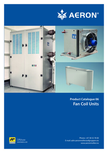
AERON FAN COIL UNIT AFCU-AAeron fan coil unit are designed for local cooling in steer gear room, thruster room or similar. It is made out of galvanized steel plates. It is equipped with a drip tray with four outlets for condensate water. It shall be connected to a chilledwater plant and it is designed for 100% return air.The fan coil is equipped with a 1-speed electrical motor, IP-55, suitable for marine environments. The unit can be delivered with a control panel for start/stop of unit. It can also be controlled with a frequency converter as an option.The fan coil is standard delivered with side cover on both sides. A protection grid on air inlet is standard for protectionof fins.PC 06 sec 03 – 2016-11-03Right to alterations reserved2
AERON FAN COIL UNIT AFCU-AAIR DATA:TypeAir volumeFace 0-CW-AAFCU-40-CW-AAFCU-50-CW-A2.900 m3/h2.900 m3/h2.900 m3/h4.600 m3/h4.600 m3/h6.000 m3/h2,31 m/2,31 m/s2,31 m/s2,30 m/s2,30 m/s3,31 -CW-AAFCU-40-CW-AAFCU-50-CW-AInlet temperature30ºC30ºC30ºC30ºC30ºC30ºCAir pressure drop46,7 Pa70,0 Pa93,3 Pa67,3 Pa89,7 Pa89,7 PaOutlet ºCInlet humidityOutlet humidity35% RH35% RH35% RH35% RH35% RH30% RH71,6% RH81,9% RH87,8% RH83,3% RH91,4% RHNoise level66 dB68 dB73 dB79 dB78 dB81 dBCooling capacity15 kW20 kW25 kW30 kW40 kW50 kWFLUID SIDE 30-CW-AAFCU-40-CW-AAFCU-50-CW-AWater inlettemperature6ºC6ºC6ºC6ºC6ºC6ºCWater er flowWater pressure drop Condensate0,63 l/s0,84 l/s1,05 l/s1,26 l/s1,68 l/s2,10 l/s19,2 kPa14,9 kPa28,1 kPa12,0 kPa29,2 kPa12,2 kPa1,4 l/h1,7 l/h2,1 l/h2,2 l/h4,4 l/h5,8 l/hFrequency50Hz/ 60Hz50Hz/ 60Hz50Hz/ 60Hz50Hz/ 60Hz50Hz/ 60Hz50Hz/ 60Hz50Hz/ 60Hz50Hz/ 60Hz50Hz/ 60Hz50Hz/ 60Hz50Hz/ 60Hz50Hz/ 60HzPower0,18kW/ 0,21kW0,18kW/ 0,21kW0,18kW/ 0,21kW0,18kW/ 0,21kW0,55kW/ 0,55kW0,55kW/ 0,64kW0,55kW/ 0,55kW0,55kW/ 0,64kW0,55kW/ 0,55kW0,55kW/ 0,64kW0,75kW/ 0,75kW0,75kW/ 0,87kWRated currentΔ1,40A/ 1,40AY0,79A/ 0,80AΔ1,40A/ 1,40AY0,79A/ 0,80AΔ2,82A/ 2,82AY1,62A/ 2,82AΔ2,82A/ 2,82AY1,62A/ 2,82AΔ2,82A/ 2,82AY1,62A/ 2,82AΔ3,57A/ 3,57AY3,05A/ 2,08AELECTRICAL W-A3 motorMS-71 1-6MS-71 1-6MS-71 1-6MS-71 1-6MS-71 3-4MS-71 3-4MS-71 3-4MS-71 3-4MS-71 3-4MS-71 3-4MS-80 2-4MS-80 -CW-AAFCU-40-CW-AAFCU-50-CW-APC 06 sec 03 – 2016-11-03VoltageΔ 230VY 440VΔ 230VY 440VΔ 230VY 440VΔ 230VY 440VΔ 230VY 440VΔ 230VY 440VGross weight w/el-motor130 kg135 kg145 kg195 kg205 kg215 kgNet weight w/el-motor71 kg78 kg85 kg103 kg112 kg133 kgRight to alterations reservedWeight el-motor6,0 kg6,0 kg7,8 kg7,8 kg7,8 kg10,6 kg3
AERON FAN COIL UNIT 498K303535353030XXØ35Ø35Ø35Ø35Ø35Ø35PC 06 sec 03 – 2016-11-03Right to alterations reserved4
Product Catalogue 06 sec 04Fan Coil Unit type AFCU-BPhone: 47 38 32 78 00E-mail: adm.aeronmollier@afgruppen.nowww.aeronmollier.no
AERON FAN COIL UNIT AFCU-BPC 06 sec 04 – 2016-10-28Right to alterations reserved2
AERON FAN COIL UNIT AFCU-BAeron fan coil unit type B is designed for local cooling in technical room, Instrument room, Engine control room andsimilar.Aeron fan coil type B comes in 3 different models; with a plenum chamber, prepared for duct or down stream.For the plenum chamber unit the air stream can be adjusted, both in vertically and horizontally direction.The unit is made of galvanized steel plates. It is insulated and equipped with a drip tray with outlet for condensatewater.It shall be connected to a chilled water plant, added 15% Ethylene glycol, and is designed for 100% return air.The inside fan is mounted on vibration dampers.The fan coil is equipped with a 1-speed electrical motor, Insulation class F, suitable for marine environments. The unitwill be delivered with built in control panel for Start/Stop of unit as a standard.Optional it can be controlled with a frequency converter, or from a remote panel.All units are delivered with a G4 filter on air inlet. Dirty or damaged filter must be replaced. Easy access to fan, coolingcoil and filter inside unit through hinged front door. The units are standard delivered with a set of mounting brackets,for secure installation.PC 06 sec 04 – 2016-10-28Right to alterations reserved3
AERON FAN COIL UNIT AFCU-BAIR DATA:TypeAir volumeFace velocityInlet U-25-CW-BAFCU-30-CW-BAFCU-40-CW-BAFCU-50-CW-B1.700 m3/h2.500 m3/h3.800 m3/h4.500 m3/h5.500 m3/h7.000 m3/h8.000 m3/h2,13 m/s2,24 m/s2,34 m/s2,15 m/s2,18 m/s2,16 m/s1,91 CW-BAFCU-10-CW-B PlenumAFCU-15-CW-BAFCU-15-CW-B PlenumAFCU-20-CW-BAFCU-20-CW-B PlenumAFCU-25-CW-BAFCU-25-CW-B PlenumAFCU-30-CW-BAFCU-30-CW-B PlenumAFCU-40-CW-BAFCU-40-CW-B PlenumAFCU-50-CW-BAFCU-50-CW-B PlenumExternal air pressure350 Pa50 Pa350 Pa50 Pa350 Pa50 Pa350 Pa50 Pa450 Pa50 Pa450 Pa50 Pa450 Pa50 PaOutlet t humidityOutlet humidity50% RH50% RH50% RH50% RH50% RH50% RH50% RH91% RH83,5% RH91% RH88,2% RH89% RH86% RH80,7% RHNoise level74 dB65 dB73 dB65 dB75 dB67 dB73 dB67 dB67 dB77 dB70 dB77 dB70 dB77 dBCooling capacity10 kW10 kW15 kW15 kW20 kW20 kW25 kW25 kW30 kW30 kW40 kW40 kW50 kW50 kWFLUID SIDE 25-CW-BAFCU-30-CW-BAFCU-40-CW-BAFCU-50-CW-BWater inlet temperature6ºC6ºC6ºC6ºC6ºC6ºC6ºCWater outlet r flowWater pressure drop Condensate0,4 l/s0,6 l/s0,8 l/s1, l/s1,2 l/s1,6 l/s2,0 l/s50 kPa50 kPa50 kPa80 kPa80 kPa80 kPa80 kPa3,94 l/h6,57 l/h8,66 l/h10,26 l/h12,54 l/h15,96 l/h18,24 l/hPower0,37kW/0,37kW/ 0,43kW0,75kW/ 0,87kW0,75kW/ 0,87kW1,1kW/ 1,3kW1,1kW/ 1,3kW0,55kW/ 0,64kW0,55kW/ 0,64kW1,5kW/ 1,7kW1,5kW/ 1,7kW0,55kW/ 0,64kW0,55kW/ 0,64kW1,5kW/ 1,7kW1,5kW/ 1,7kW0,75kW/ 0,87kW0,75kW/ 0,87kWRated current0,43kWY1,25A/ 1,35AELECTRICAL DATA:TypeAFCU-10-CW-BAFCU-10-CW-BAFCU-10-CW-B PlenumAFCU-10-CW-B PlenumAFCU-15-CW-BAFCU-15-CW-BAFCU-15-CW-B PlenumAFCU-15-CW-B PlenumAFCU-20-CW-BAFCU-20-CW-BAFCU-20-CW-B PlenumAFCU-20-CW-B PlenumAFCU-25-CW-BAFCU-25-CW-BAFCU-25-CW-B PlenumAFCU-25-CW-B PlenumPC 06 sec 04 – 2016-10-283 motorMS-80 M1 1-6MS-80 M1 1-6MS-80 2-4MS-80 2-4MS-80 3-4MS-80 3-4MS-80 M2-6MS-80 M2-6MS-90 L-4MS-90 L-4MS-80 M2-6MS-80 M2-6MS-90 L-4MS-90 L-4MS-90 S-6MS-90 S-6VoltageΔ 230VY 440VΔ 230VY 440VΔ 230VY 440VΔ 230VY 440VΔ 230VY 440VΔ 230VY 440VΔ 230VY 440VΔ 230VY 440VFrequency50Hz/ 60Hz50Hz/ 60Hz50Hz/ 60Hz50Hz/ 60Hz50Hz/ 60Hz50Hz/ 60Hz50Hz/ 60Hz50Hz/ 60Hz50Hz/ 60Hz50Hz/ 60Hz50Hz/ 60Hz50Hz/ 60Hz50Hz/ 60Hz50Hz/ 60Hz50Hz/ 60Hz50Hz/ 60HzRight to alterations reservedY2,05A/ 2,25AY2,7A/ 3AY1,75A/ 1,9AY3,5A/ 3,8AY1,75A/ 1,9AY3,5A/ 3,8AY2,2A/ 2,4A4
AERON FAN COIL UNIT AFCU-BAFCU-30-CW-BAFCU-30-CW-BAFCU-30-CW-B PlenumAFCU-30-CW-B PlenumAFCU-40-CW-BAFCU-40-CW-BAFCU-40-CW-B PlenumAFCU-40-CW-B PlenumAFCU-50-CW-BAFCU-50-CW-BAFCU-50-CW-B PlenumAFCU-50-CW-B PlenumMS-90 L2-4MS-90 L2-4MS-90 L-6MS-90 L-6MS-100 L1-4MS-100 L1-4MS-90 L-6MS-90 L-6MS-100 L2-4MS-100 L2-4MS-100 L-6MS-100 L-6TypeAFCU-10-CW-B, PlenumAFCU-10-CW-B, Down stream/ DuctAFCU-15-CW-B, PlenumAFCU-15-CW-B, Down stream/ DuctAFCU-20-CW-B, PlenumAFCU-20-CW-B, Down stream/ DuctAFCU-25-CW-B, PlenumAFCU-25-CW-B, Down stream/ DuctAFCU-30-CW-B, PlenumAFCU-30-CW-B, Down stream/ DuctAFCU-40-CW-B, PlenumAFCU-40-CW-B, Down stream/ DuctAFCU-50-CW-B, PlenumAFCU-50-CW-B, Down stream/ DuctPC 06 sec 04 – 2016-10-28Δ 230VY 440VΔ 230VY 440VΔ 230VY 440VΔ 230VY 440VΔ 230VY 440VΔ 230VY 440V50Hz/ 60Hz50Hz/ 60Hz50Hz/ 60Hz50Hz/ 60Hz50Hz/ 60Hz50Hz/ 60Hz50Hz/ 60Hz50Hz/ 60Hz50Hz/ 60Hz50Hz/ 60Hz50Hz/ 60Hz50Hz/ 60HzNet weight w/el-motor180 kg180 kg200 kg200 kg260 kg240 kg280 kg260 kg300 kg300 kg330 kg340 kg370 kg370 kgRight to alterations reserved2,2kW/ 2,5kW2,2kW/ 2,5kW1,1kW/ 1,3kW1,1kW/ 1,3kW2,2kW/ 2,6kW2,2kW/ 2,5kW1,1kW/ 1,3kW1,1kW/ 1,3kW3,0kW/ 3,6kW3,0kW/ 3,5kW1,5kW/ 1,8kW1,5kW/ 1,7kWY4,8A/ 5,2AY3,1A/ 3,4AΔ8,12A/8,12AY4,7A/ 5,2AΔ5,48A/ 5,48AY3,1A/ 3,4AΔ11,5A/ 11,5AY6,6A/ 7,2AΔ6,78A/ 6,78AY3,8A/ 4,1AWeight el-motor10 kg12 kg12 kg13,5 kg12 kg17 kg14 kg17 kg1718172323265
AERON FAN COIL UNIT -BAFCU-15-CW-BPlenumDuctPC 06 sec 04 – 2016-10-28Right to alterations reserved6
AERON FAN COIL UNIT AFCU-BAFCU- ‐15- ‐CW- ‐BAFCU- ‐15- ‐CW- PC 06 sec 04 – 2016-10-28Right to alterations reserved7
AERON FAN COIL UNIT CW-BAFCU-25-CW-BDuctPlenumPC 06 sec 04 – 2016-10-28Right to alterations reserved8
AERON FAN COIL UNIT -BAFCU-40-CW-BPlenumBottomPC 06 sec 04 – 2016-10-28Right to alterations reserved9
AERON FAN COIL UNIT AFCU-BAFCU-40-CW-BAFCU-50-CW-BDuctBottomAFCU- ‐50- ‐CW- ‐BDuctPC 06 sec 04 – 2016-10-28Right to alterations reserved10
Product Catalogue 06 sec 05Fan Coil Unit type CCUPhone: 47 38 32 78 00E-mail: adm.aeronmollier@afgruppen.nowww.aeronmollier.no
FAN COIL UNIT TYPE CCUThe Air Condition Unit is specially designed for roomswhich needs cooling or heating.The unit uses only the necessary energy which is neededat the moment.What is special with this Air Condition Unit, is the variousspeed of fan, cooperated with the control function forcooling or heating.You may imagine a warm summers day, with sunshinethrough your display windows, and a temperature whichrises above 30ºC. Just start up this Air Condition Unit, andyou will feel refreshed.Maybe you have a computer room or switchboard roomwhich needs temperature control? The unit will work foryou whether it is installed on board ships, offshore platforms or in onshore buildings.The AC Unit is easy to install, and needs only to be connected to water and power supply.The CCU Unit can be delivered for duct connections, withplenum chamber and for downstream. The downstreamunit may be used for raised floor for cooling of computersand instrumenCoolingAir flowcapacityFan motor50/60HzMax currentTECHNICAL DESCRIPTION: Capacities 10-55 kW Casing material in galvanized steel and insulated with50mm sound insulation. Inside sound insulation Filter G4 for inlet air in front door. Coil in Cu/Al Drip pan in aluminium. Drain connection 1”. Painted casing in grey-white (RAL 9002) Electric panel with control system. EC – electronically commutated motor with variousspeed controls. Insulated plenum chamber or duct connection, up ordown stream.OPTIONS: Casing in stainless steel Coil in Cu/Cu Coil in Cu/AlMg Direct Expansion Heating coil (either hot water or electric)GENERAL DESCRIPTION:CCUWxx: Unit for chilled waterCCUDxx: Unit for direct expansionWater flowPressureChilledElectricBased ondrop,water con-heatvoltage 3x230waternectionSoundV 3x400 V3x440 VSizekWm³/hkWA[l/s][kPa]Inch0112,718001 x 0,5054,1 / 4,1 / 4,10,514,90217,529002 x 0,5057,2 / 7,2 / 7,20,725,60320,437002 x 0,5057,2 / 7,2 / 7,20,80430,545001 x 1,75,5 / 3,6 / 3,60535,757002 x 1,07,0 / 4,4 / 4,40644,966001 x 3,00755,186002 x 1,7PC 06 sec 05 – 01¼”24751,523,81¼”24767,6 / 5,6 / 5,61,824,91½”247910,0 / 6,2 / 6,22,236,01½”2484Right to alterations reserved2
FAN COIL UNIT TYPE CCUCONTROL FUNCTIONTemperature sensor in air inlet, ensures correct temperature in the room. Temperature sensor in air outlet, gives thepossibility to limit minimum and maximum supply air temperature.With heat requirement the speed on fan is adjusted in parallel with admission to heating coil within min and max ofrational speed and temperature on fan.With cooling demand with on-off-ventilator, the cooling valve will open, and the fan goes to max speed.With cooling demand with 3-ways modulating valve, the speed on fan is adjusted in parallel with admission to coolingcoil within min and max fan speed.Between heating and cooling sequency, there is a dead zone (4% of general survey chartes) where the fan goes toadjusted min. speed for heating/cooling.Max and min limitations can be adjusted in the display, but this is set as standard values at factory. (min 10ºC andmax 30ºC).The unit operates from “off-man-auto” functions in the display.In “auto” the unit starts/stops via an internal timer inside the regulator.PC 06 sec 05 – 2016-10-28Right to alterations reserved3
FAN COIL UNIT TYPE CCUInsulated plenum chamber or ductconnectionUp- or downstreamSolution for DX coolingSIZE CHARTSizeCoolingcapacitykW0112,70217,503Air flowWidthDepthm³/hmmmm1 8001 0067062 9001 00670620,43 7001 0060430,54 5000535,70607HeightWeightHeight (H)compressorsectionmmKgmm1 6902507001 6902507007061 6902507001 2068061 6902908005 7001 2068061 69029080044,96 6001 6069061 69037080055,18 6001 6069061 690370800FAST SELECT CHART010203040506070PC 06 sec 05 – 2016-10-28102030Right to alterations reserved405055 kW4
Product Catalogue 06 sec 06Carrier Fan Coil 42NProduct SelectionPhone: 47 38 32 78 00E-mail: adm.aeronmollier@afgruppen.nowww.aeronmollier.no
CARRIER FAN COIL 42NP R O D U C T S E L E C T I O N D ATA Extremely quiet operation Low Energy Consumption Simpified installation &large options choice Self regulated PTCelectrical heater Discreet & elegantconsolerRoom Fan Coils42NCARRIER participates in the ECP programme for LCP/HPCheck ongoing validity of iflash.comOriginal instructionsPC 06 sec 06 – 2016-10-31Right to alterations reserved2
CARRIER FAN COIL 42NTOTAL COOLING CAPACITY 0.75–7.2 KWTOTAL HEATING CAPACITY 0.60–9.26 KWThis document only contains limited selection of typesand technical data for which Aeron mostly uses.The new generation 42N S and 42N E product rangescombine aesthetic and attractive design with versatilityto satisfy any application need, from large office buildingsor hotels to shops and residential applications.This new product series is characterised by concentrated,innovative technology, unusual for a fan coil. The result isa product that is easy to select and install.The 42N S is available with a new-generation three- orfive-speed AC motor. The 42N E is available with a variable-speed low energy consumption EC motor.The range now includes eleven sizes, with air flows from35 to 422 l/s (126 to 1520 m3/h). The Idrofan offers anultra-low-noise option for applications where a low noiselevel is the most important selection parameter.MOTORSThe Idrofan is available with a multi-speed motor, extended to five fixed speeds to improve its flexibility and cover all customer applications. The Idrofan is now availablewith ultra-low noise levels to make it one of the quietestfan coils on the market.The Idrofan is also available with variable-speed LEC ( low energy consumption) motors, that meet the newbuilding energy performance objectives.The LEC solution enhances unit performances offering: Reduced energy costs - the LEC motor reduces fan coilconsumption by 50 to 75%. The LEC option meets thenew building energy management regulations.Improved comfort - the LEC motor with variable fanspeed reduces noise levels compared to multi-speedfans, offering ultra-quiet air flow down to very lowoperating levels. With the NTC controller, a maximumfan speed can be set to allow better sound level management.Maximum flexibility - auto-adaptive air flow rateadjust-ment from 0 to 100% ensures perfect coolingand heating conditions in the room.Extended life time - LEC motors with brushlesstechno-logy use a lower fan motor temperature forextended operating life.The new Idrofan is available with two types of fans, atangential fan for the smallest sizes and a centrifugal fanfor all other sizes. These versions are available in any combination, from cabinet models for floor, wall or under-ceiling installation tomodels without cabinet for horizontal or vertical furred-ininstallation.FILTERSThe standard filter for the Idrofan series has a pleatedfiltration surface, resulting in a 87% larger surface than aconventional filter, with the following additional advantages:FEATURES With its sleek styling the 42N encased units blend in perfectly with any room décor. The pre-painted steel panelsare protected by a high-quality paint finish.Integrated, factory-mounted cooling and heating coil forfour-pipe applications.The 42N units were designed for extremely quiet operation with sound levels that set new comfort standards forbuildings. The new fan/motor assembly design ensureswhisper-quiet operation (10 dB(A) less compared to theprevious version). Particular attention has been given tothe low fan speed, typically used at night.PC 06 sec 06 – 2016-10-31 Lower air flow per unit area, resulting in lower pressure drop and reduced noise level.The average interval between filter cleaning is threetimes longer, compared to standard filters.The filter material is polypropylene and the grade is G1.In the Idrofan series the filter is located at the bottom ofthe unit. Cleaning is easy: after removing a safety screw,the filter sides can be manually unclipped. The filter framecan be pulled down and the filter can then be removedeasily. Re-assembly is just as easy, reversing the sequence.The filter and filter position within the unit are designedto prevent air bypass around the filter, to ensure that theair is always filtered and clean.Right to alterations reserved3
CARRIER FAN COIL 42NEASE OF INSTALLATIONThe installation of floor-mounted units is simple, thenew hook dimensions and positions help fixing the unitsfirmly against the wall.All these design aspects minimise installation time andimprove the long-term reliability, avoiding small mistakesthat could impair the reliability of installed units overtime.CARRIER CONTROLLER RANGEThe Idrofan fan coil is available with the complete rangeof Carrier controllers. Several tests ensure easy installation. The number of available controllers offers moreand improved features, and easy selection according toapplication needs.ELECTRONIC THERMOSTAT A-B-C-D TYPESCarrier electronic thermostat range is available for allCarrier hydronic terminals ranges: Type A: Two-pipe application with AC motorsType B: Four-pipe or two-pipe applications with electric heaters with AC motorsType C: Two-pipe application with EC motorsType D: Four-pipe or two-pipe applications with electric heaters with EC motorsThe thermostat for FCU with EC motors option is managing 3 configurable discrete speeds through 0-10 Vsignal.The thermostats have an elegant square shape with acoaxial knob to set room temperature and 3 buttons toset up fan speed, cooling or heating mode, and On/Off, asdesired by the customer.Wall-mounted controls are easily and discreetly integrated in any room environment.The electronic thermostats set range is from10 C to 30 C with the possibility to limit the temperature in publicbuildings where low energy consumption is a key requirement via a dip-switch inside the control (Cooling range23 C/30 C, heating range 10 C/21 C).The following Features are available as setting:–– Auto fan: The fan speed is automatically set by thecontrol; when the room temperature is far from theset point, high fan speed is selected. As the room temperature approaches the desired value, the fan speeddecreases until the minimum speed is reached.PC 06 sec 06 – 2016-10-31–– Automatic changeover: Automatic changeover fromthe cooling to heating mode, based on the watertemperature, ensures that the ideal room temperatureis maintained.–– Remote changeover: Automatic changeover fromcooling to heating mode, based on the remote signalfrom the monitoring system.–– Warm and cold draught protection: This feature stopsthe fan when the set point condition is satisfied andthe water temperature is too low or too high, ensuringthat air that is too cold or too warm does not causediscomfort to the room occupants.–– Air sensor: This is unit-mounted – if the control is wallmounted, a second air sensor located in the controlcan be used for fine tuning of the desired room temperature.–– Frost protection: This function ensures that the roomtemperature is kept above a minimum level. If the unitis in off mode, and the room temperature drops below7 C, frost protection is enabled and the unit operatesin heating mode until the temperature rises above 9 C. At this point the unit is switched off again.–– Booster heating management optimization(available with electric heater option): If the watertemperature is below 30 C the system will work in theheat demand mode and the electric heater will be theonly available heating source. If the water temperature is above 35 C the system will work in the boosterheating mode, energising the water valve and electricheater together. The booster heating function will bedeactivated if the water temperature is above 45 C(the electric heater will be de-energised).–– Energy saving: This feature allows saving energywhen the room is unoccupied, without the need toswitch off the unit. When the energy-saving button ispressed, the actual set point will be modified as follows, without changing the position of the set pointselection knob: - Cooling mode: Set point raised by 4 C - Heating mode: Set point lowered by 4 C The unitwill resume normal operation, once the energy savingbutton is pressed again.–– LED intensity: For offices or light commercial applications, 10 seconds after the latest use of the userinterface, all the necessary LEDs are lighted on at areduced intensity. As soon as the user touches againthe user interface, LED have to come back to normalRight to alterations reserved4
CARRIER FAN COIL 42Nlight. In order not to disturb hotels customers, the thermostat can be configured from Night Mode to DarkMode: 10 seconds after the latest use of user interface, all the LEDs are switched off. As soon as the usertouches again the user interface, LEDs of the currentcondition are switched on with normal light.–– Air sampling: If no fan request is made and the Airsampling jumper is in ON position, the control performs the Air sampling function: the air is moved inthe room, thermal stratification is reduced, ensuring amore reliable ambient temperature reading.–– Continuous fan: If there is no fan request and theContinuous fan jumper is in ON position, the controlselects fan speed Low, Medium or High according tothe fan-speed selection, regardless of thermal stationconditions. If the fan is controlled in Auto fan modeand the control is not in the demand phase, the fan ispermanently activated at Low speed.–– External contact: A high voltage input signal forexternal contact is present. If the external contactis activated, device behaviour depends on its configuration on site: - Presence detection (empty roomwith hotel door card), Energy saving mode is activated, internal temperature is raised by 4 C in coolingmode and reduced by 4 C in heating mode. - WindowContact: During OFF mode (window open), all outputsare disconnected (fan, valves, etc.) and only the frostprotection.–– Master/Slave control: Thermostat type A AC andB AC: the Control Board for grouping accessory(42N9006) is allowing fan speed relay only (watervalves have to be wired/relayed separately) up to 300units with control on Air temperature (no water valve),or 10 units 2 pipe with water control, or 5 units 4 pipewith water control - Thermostat type C EC and D EC:The Thermostat EC motor version can control up to10 LEC units by wiring in parallel the analogue 0-10two-wires output signal (water valves have to bewired/relayed separately).NTC CONTROLLERThis is a communicating PID controller, combining energy-saving algorithms and full control function solutions,compatible with the Aquasmart Evolution system package. The NTC controller can manage the EC motor option,and combines energy savings with optimised comfort.VALVE OPTIONSValve body: both the two-way or four-way (three-waywith integrated bypass) valve options are factory-fittedand tested. The chilled-water valves are fully insulatedwithin a moulded insulating shell, preventing condensation on the valve body, for both vertical and horizontalapplications. This new shell reduces the complexity ofthe offer and prevents water leakage risk. Valves can befactory-fitted on the left or right-hand side.Valve actuators: a wide choice of actuators is availablewith two or four-way valve bodies to offer the right solution for any controller type and customer requirement,from on/off to proportional types, with either 230 V or 24V power supply: On/off 230 V actuatorOn/off 24 V actuatorFloating 3-point 230 V actuatorFloating 3-point 24 V actuatorModulating 0-10 V/24 V actuatorWhen combined with LEC motors and the NTC controller,floating three-point 230-V actuators are recommended toincrease energy savings and enhance comfort.HDB (HYDRONIC DUAL BOARD)This electronic thermostat allows master/slave operation.The master unit can manage up to 15 slave units. Thiscontroller can be used with a wall-mounted user interfaceor a remote end user control.PC 06 sec 06 – 2016-10-31Right to alterations reserved5
CARRIER FAN COIL 42NMAIN DRAIN PAN AND INSULATIONThe main drain pan incorporates innovative technologicalsolutions: Left or right-hand condensate connection is standard- the installer can easily choose unit connection onone side or the other, just by fixing the plastic cap onthe opposite side.Insulation: the drain pan design allows much tightercontact between drain pan and insulation, reinforcedby metal clips to keep the insulation in place. Thisimproves reliability and prevents water dripping fromthe unit.The drain pan for the whole range is made of moulded plastic, i.e. more robust, easier and safer toservice.PTC ELECTRIC HEATERElectric heater options have been enhanced with thelatest PTC (positive temperature coefficient) technology.Their resistance increases as their temperature increases, so the capacity goes down accordingly. This electricheater feature allows fast heating at start-up, the heatingcapacity is adjusted automatically, whilst ensuring safeand reliable operation. This option is available in low andhigh capacity for each Idrofan size.FEET MOUNTINGThe installation of feet has been greatly simplified andboth sides are painted. Just one clip is needed to fix thefeet to the units. For this reason and for better reliabilityduring transport, the feet are sold as options - suppliedwith the unit from the factory (ordering codes Z or P inthe 4th digit). They are included with the unit, but notfactory-mounted.AESTHETICS Supporting feet Supporting feet and cover panel Return air grille for cabinet unit Rear closing panel Cabinet on concealed units, Discharge air sleeve (concealed units only) Supporting brackets (20 20 pieces left and right)CONTROLLERS AND USER INTERFACES A/B/C/D-type thermostat Kit for 33TA0001/33TB0001 installation on 42NM/Z Cold draught prevention kit - all two-pipe sizes Automatic changeover switch - all units Air sensor with 15 m cable Water sensor kit with 15 m cable Infrared remote controller (IR2) Infrared remote receiver kit (IRR) ZUI1 interface 1 - Wago ZUI2 interface 2 - RJ11 SUI1 (with fan speed selection) SUI2 (without fan speed selection)The units comply with international standards EN603351 and EN60335-2-40 and are certified according to theapplicable Eurovent standards for the non-ducted fan coilprogramme.REVERSIBILITYIf the unit received is not as required, the coil and thecontrol box can be switched on site from left to right orvice versa (except units equipped with valves - since theirinstallation is optimised for each side, the valve packagemust be replaced by a new valve kit).SIMPLIFIED ACCESSORIESThe number of accessories has been reduced to simplifyselection and reduce the inventory level. The accessoriesoffered remain unchanged to satisfy any application needs, but the number of codes has been greatly reduced.PC 06 sec 06 – 2016-10-31Right to alterations reserved6
PHYSICAL AND ELECTRICAL DATA, UNITS WTIHLEC MOTORS, TWO AND FOUR-PIPE COILSPhysical and electrical data, units with LEC motors, two andfour-pipe coils42N E, 2-pipe coilFan speedFan typeAir flowCooling mode*Total cooling capacitySensible cooling capacityWater flow rateWater pressure dropHeating mode**Heating capacityWater pressure dropWater contentSound levelsSound power levelSound pressure level***NR valueElectrical dataPower inputCurrent drawnElectric heaterHigh capacityCurrent drawnLow capacityCurrent drawnEurovent dataFCEERFCEER energy classFCCOPFCCOP energy classConnection diameter42N E, 2-pipe coilFan speedFan typeAir flowCooling mode*Total cooling capacitySensible cooling capacityWater flow rateWater pressure dropHeating mode**Heating capacityWater pressure dropWater contentSound levelsSound power levelSound pressure level***NR valueElectrical dataPo
AERON FAN COIL UNIT AFCU-A Aeron fan coil unit are designed for local cooling in steer gear room, thruster room or similar. It is made out of galvani-zed steel plates. It is equipped with a drip tray with four outlets for condensate water. It shall be connected to a chilled water plant and it is designed for 100% return air.
